Cross-reference to related application
This nonprovisional application claims priority under 35 U.S.C. .sctn.119(a) on Patent Application No. 2009-243057 filed in Japan on Oct. 22, 2009, the entire contents of which are hereby incorporated by reference.
Background of the invention
1. Field of the invention
The present invention relates to a network image forming system including a server computer (hereinafter simply referred to as a "server"), an image forming apparatus and a client computer (hereinafter simply referred to as a "client"), in which the image forming apparatus forms an image based on image data stored in the server.
2. Description of the Background Art
In a company or an office (hereinafter referred to as a "company"), generally, a client computer (an information processing apparatus, a personal computer (PC) or the like) is allocated to an individual, and each client is connected to LAN (Local Area Network). Generally, the LAN is connected to the Internet. Therefore, individual in the company can use resources on the Internet using a browser or e-mail.
Image forming apparatuses having printing function (printer function) are often connected to the LAN. Such an image forming apparatus is shared in the company through the LAN. A user using a PC connected to the LAN in the company may transmit electronic data (print data) such as a word-processor document or spreadsheet document (hereinafter referred to as "word-processor document") through the LAN to the image forming apparatus, to have the document printed.
One of such image forming apparatuses is an MFP (Multifunction Peripheral). MFP has a plurality of operational modes, including copy mode, image communication mode, network-supported printer mode and scanner mode. Recently, most of the image forming apparatuses are MFPs. In the following, description will be given using an MFP as a representative image forming apparatus.
Conventionally, a network image forming system referred to as "pull-print" system for improving user convenience in a network environment including an MFP such as described above, a client (information terminal) and a server (information processing apparatus) has been known. In the pull-print system, a print job or print jobs are registered in advance by a client with the server. A print job registered with the server is selected through an operation panel of the MFP and the print job is downloaded from the server to the MFP. Based on the downloaded print job, MFP forms an image on a sheet of recording paper.
In the pull-print system as such, one MFP is shared by a number of users. Therefore, it is not uncommon that, when a user comes to an MFP for pull-printing, another person is using the operation panel. In such a situation, the user must wait until the previous user ends his/her operation. The print time for pull-printing involves the time of downloading PDL (Page Description Language) data from the server to the MFP, the time for converting the PDL data to developed data (RIP (Raster Image Processing) data), and the actual printing time. Here, the RIP data refers to data that is about to be printed, not requiring any further conversion for printing. The PDL data is formed by a printer driver of a client computer. The process for developing the PDL data to the RIP data may be executed by the server or by the MFP.
When another person is using the operation panel, the user generally waits to use the operation panel. When it becomes available, the user logs-in to the MFP, whereby the downloading of PDL data, development of PDL data to RIP data, and printing of the RIP data are executed. In such a situation, downloading of the PDL data starts only after the user logs-in to the MFP. Therefore, the user must wait for a long time in front of the MFP until the printing is done.
In view of such a problem, Japanese Patent Laying-Open No. 2007-105937 (hereinafter referred to as "'937 Reference") discloses an MFP that allows, while a user is logged-in to the MFP, reservation of a process (job) using the MFP by another user. Even while one user is logged-in to the MFP, the MFP can execute pre-processing of the reserved job. Job reservation is done by the user having an IC card recording user information read by an IC card reader of the MFP. This process is different from the process for log-in. The pre-processing includes processes of pull-printing such as downloading of print data and development of PDL data to RIP data, other than image formation.
With this MFP, even when one user is logged-in to the MFP, another user having an IC card can make a reservation of a job using the MFP. Before log-in of the said another user, pre-processing of the reserved job is done by the MFP. Therefore, the time necessary for the user who made the reservation to obtain the print output (print wait time) can be reduced.
The MFP, however, still has a room for improvement. Specifically, it is necessary to have the IC card reader of the MFP to read the IC card information for reservation.
Japanese Patent Laying-Open No. 2006-47765 (hereinafter referred to as "'765 Reference") discloses a possible solution to this problem. '765 Reference discloses an MFP having an IC tag reader-writer, detecting whether or not a user is approaching. If there is an IC tag in a range of radio wave generated by the IC tag reader-writer, communication between the IC tag reader-writer and the IC tag becomes possible. As a result, the MFP can detect that the user having the IC tag is approaching the MFP.
By combining the MFP disclosed in '937 Reference with the MFP configuration (IC tag reader-writer) disclosed in '765 Reference, a configuration would be obtained in which an approaching user is automatically recognized by the MFP and reservation is made automatically. Even in such a configuration, printing cannot be started until the user logs-in. Therefore, the time until the user obtains the print output cannot be reduced.
The MFP disclosed in '937 Reference is based on the premise that a user who wishes to have print data stored in the server printed by the MFP comes to the intended MFP. A user who is unaware of any data to be printed or a user who forgets that there is some data to be printed may not go to the MFP. Even if such a user should come close to the MFP, he/she may not recognize the necessity to log-in to the MFP to print the data that should be printed. Therefore, even if data to be output is stored in the server, the data may not be output and left as it is.
Summary of the invention
In order to solve the above described problem, a system of forming an image by a network-connected image forming apparatus is desired, by which even a user not aware of print data that should be output from the image forming apparatus by logging-in can obtain the print data in a short period of time when the user approaches the image forming apparatus. Further, there is a demand for a server and an image forming apparatus used in such an image forming system.
According to a first aspect, the present invention provides a server computer used in a network image forming system. The system includes the server computer accumulating image forming jobs, a client computer forming an image forming job and transmitting the job to the server computer, and an image forming apparatus transmitting user information received through noncontact communication within a predetermined range to the server computer and forming an image using data received from the server computer. The server computer includes: an accumulating device accumulating image forming jobs received from the client computer; a first receiving device receiving user information from the image forming apparatus; a searching device searching for an image forming job corresponding to the user information received from the image forming apparatus from among the image forming jobs accumulated in the accumulating device; and a transmitting device connected to the searching device, for transmitting the image forming job necessary for image formation, searched out by the searching device, to the image forming apparatus that transmitted the user information.
The server may further include an image data developing device developing data allowing image formation by the image forming apparatus that transmitted the user information, based on the searched out image forming job.
According to a second aspect, the present invention provides a program product including a computer-readable recording medium. The recording medium stores a computer program causing, when executed by a computer, the computer to operate as the above-described server computer.
According to a third aspect, the present invention provides a data processing method by a server computer used in a network image forming system. The system includes the server computer accumulating image forming jobs, a client computer forming an image forming job and transmitting the job to the server computer, and an image forming apparatus transmitting user information received through noncontact communication within a predetermined range to the server computer and forming an image using data received from the server computer. The method includes the steps of: accumulating image forming jobs received from the client computer; receiving user information from the image forming apparatus; searching for an image forming job corresponding to the user information received from the image forming apparatus from among the accumulated image forming jobs; and transmitting the image forming job necessary for image formation, searched out at the searching step, to the image forming apparatus that transmitted the user information.
According to a fourth aspect, the present invention provides an image forming apparatus used in a network image forming system. The system includes the image forming apparatus, a server computer accumulating image forming jobs and transmitting data of accumulated image forming job corresponding to user information received from the image forming apparatus to the image forming apparatus that transmitted the user information, and a client computer forming an image forming job and transmitting the job to the server computer. The image forming apparatus includes: a communication device receiving user information by noncontact communication in a predetermined range; a transmitting device transmitting the user information received by the communication device to the server computer; a receiving device receiving data necessary for image formation by itself from the server computer; and an image forming unit forming an image using the data received by the receiving device from the server computer.
According to a fifth aspect, the present invention provides a program product including a computer-readable recording medium. The recording medium stores a computer program causing, when executed by a computer, the computer to operate as the above-described image forming apparatus.
In the network image forming system as described above, an image forming job formed by a client (the image forming job refers to data necessary for forming an image by the image forming apparatus, including data of various forms) is transmitted to and stored in the server. If a user holding a noncontact communication tag comes within a predetermined range from the image forming apparatus, the image forming apparatus receives user information through noncontact communication, and transmits the information to the server. The server searches for an image forming job corresponding to the user information received from the image forming apparatus, from among the stored image forming jobs. Based on the searched out image forming job, the server forms data necessary for image formation (data necessary for image formation by the image forming apparatus as the transmission destination), and transmits the data to the image forming apparatus as the source of user information. Receiving the data necessary for image formation from the server, the image forming apparatus forms image using the received data (for example, prints and outputs an image on a sheet of recording paper (print)).
When the user whose user information corresponds to the image forming job stored in the server simply comes closer to the image forming apparatus, the server searches for the image forming job corresponding to the user, forms data necessary for image formation, and transmits the data to the image forming apparatus. It is unnecessary for the user to log-in to the image forming apparatus, and when the user simply approaches the image forming apparatus, the image forming job can be output from the image forming apparatus. When the user simply approaches the image forming apparatus, data necessary for image formation is transmitted from the server to the image forming apparatus. Therefore, the time necessary for image formation (wait time) can significantly be reduced. For instance, it is possible to have the output completed by the time the user reaches the image forming apparatus. As a result, even if the user has no idea of getting image output from the image forming apparatus, an image intended for the user can be formed quickly on a sheet of paper and output, when the user simply comes close to the image forming apparatus.
As described above, in the system of forming an image by an image forming apparatus connected through a network, even if the user has no idea of getting image output from the image forming apparatus, an image intended for the user can be formed quickly by the image forming apparatus to which user approaches.
The foregoing and other objects, features, aspects and advantages of the present invention will become more apparent from the following detailed description of the present invention when taken in conjunction with the accompanying drawings.
Brief description of the drawings
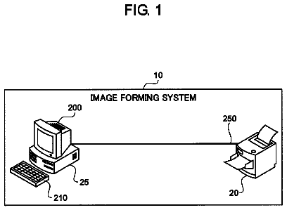
FIG. 1 shows an overall configuration of the network print system in accordance with an embodiment of the present invention.
FIG. 2A is a control block diagram showing hardware configuration of a client PC shown in FIG. 1.
FIG. 2B schematically shows a list of functions realized by a program executed by a CPU (Central Processing Unit) of the PC shown in FIG. 1.
FIG. 3A is a control block diagram showing hardware configuration of a server shown in FIG. 1.
FIG. 3B schematically shows a list of functions realized by a program executed by a CPU of the server shown in FIG. 1.
FIG. 4A is a control block diagram showing hardware configuration of an MFP shown in FIG. 1.
FIG. 4B schematically shows a list of functions realized by a program executed by a CPU of the MFP shown in FIG. 1.
FIG. 5 shows conditions for giving an alarm to the user (hereinafter referred to as user alarm conditions) in the network print system in accordance with an embodiment of the present invention.
FIG. 6 shows a user alarm conditions management table managed in the server shown in FIG. 1.
FIG. 7 shows a data format of attribute information managed with print data stored in the server shown in FIG. 1.
FIG. 8 shows specific examples of the attribute information of FIG. 7.
FIGS. 9A and 9B are flowcharts representing a control structure of a print data forming program executed by the client.
FIG. 10 is a flowchart representing a control structure of an uploading program executed by the client.
FIGS. 11A and 11B are flowcharts representing a control structure of an approaching-user-triggered program executed by the MFP.
FIG. 12 is a flowchart representing a control structure of a print data accumulation program executed by the server.
FIGS. 13A and 13B are flowcharts representing a control structure of a print data transmission program executed by the server.
FIGS. 14 and 15 are exemplary images on a touch-panel display of the MFP when the program of FIGS. 11A and 11B is executed.
Description of the preferred embodiments
In the following description, the same components are denoted by the same reference characters. Their names and functions are also the same. Therefore, detailed description thereof will not be repeated. In the following, the image forming apparatus is an MFP. The image forming apparatus, however, is not limited to an MFP. Any image forming apparatus including at least a network-supported printing function may be used. The network print system in accordance with the present embodiment is an example of a network image forming system, and it includes a client, a server accumulating print data transmitted from the client, and an MFP forming an image on a sheet of recording paper based on the print data received from the server. Here, transmission of print data from the client to the server will be referred to as "data uploading."Reception of data by the MFP from the server will be referred to as "print data downloading." In the present embodiment, the downloaded data is assumed to be RIP data developed from the PDL data. Since the MFP downloads the RIP data from the server, data conversion in the MFP becomes unnecessary, and therefore, the print time in the MFP can advantageously be made shorter. It is noted, however, that the downloaded data may have other format (for example, PDL data). Data necessary for image formation in the MFP may be generally referred to as image forming job.
[Overall System Configuration]
In the following, a user who forms print data such as word processor document on the client will be simply referred to as a "creator." A user who has the print data prepared by the creator printed by the MFP will be simply referred to as a "user."
Referring to FIG. 1, the network print system in accordance with the present embodiment includes: a server 200 accumulating print data; clients 100, 102, 104, 106 and 108 uploading print data such as the word processor document prepared by the creator to server 200; and MFPs 300, 302 and 304 downloading RIP data from server 200 and printing images on sheets of paper, respectively. In response to a request from MFPs 300 to 304, the server transmits RIP data from among the accumulated print data, to the MFP that transmitted the request. Clients 100, 102, 104, 106 and 108, server 200, and MFPs 300, 302 and 304 are connected to be communicable with each other by a network line 400 in compliance with, for example, IEEE802.3. In the following description, clients 100, 102, 104, 106 and 108 will be represented by client 100, and MFPs 300, 302 and 304 will be represented by MFP 300, respectively.
Server 200 stores a list of users who are permitted to use the network print system.
In the network print system, basically, the word processor documents and the like are converted by a printer driver installed in the client to PDL data. The converted PDL data is transmitted to and stored in the server.
The number of client 100, the number of server 200 and the number of MFP 300 are not limited to those shown in FIG. 1. Further, in the following and in the drawings, client 100 may be simply referred to as a client or a PC, and server 200 may be simply referred to as a server.
[Hardware Configuration]
<Client 100>
Referring to FIGS. 2A and 2B, client 100 includes: a bus 190; a CPU 110 connected to bus 190; an ROM (Read Only Memory) 120 connected to bus 190; an RAM (Random Access Memory) 130 connected to bus 190; a hard disk (HDD) 140 connected to bus 190; an optical disk drive 180 connected to bus 190, to which an optical disk 182 can be mounted, capable of writing information to and reading information from optical disk 182; an input interface (hereinafter referred to as "input I/F") 150 connected to bus 190, providing an interface for connection to a mouse 152 and a keyboard 154; a display interface (hereinafter referred to as "display I/F") 160, connected to bus 190, providing an interface for connection to a display 162; and a network interface (hereinafter referred to as "network I/F") 170 providing wired or wireless (in the present embodiment, wired) connection to network line 400. Client computer 100 may include a magnetic disk drive, to which a magnetic disk can be mounted, capable of writing information to and reading information from the magnetic disk, in place of/in addition to optical disk drive 180. Network I/F 170 may be an interface for wireless connection to network line 400, and client 100 may be a notebook type device.
Bus 190, ROM 120, RAM 130, hard disk 140, optical disk drive 180, input I/F 150, display I/F 160 and network I/F 170 cooperate with each other under the control of CPU 110, and realize processes of various applications in client 100. These applications include, for example, the processes for producing word processor documents, spreadsheet documents, and uploading process for transmitting the print data formed by such processes to server 200.
A computer program causing client 100 to execute the processes mentioned above is stored in optical disk 182 inserted to optical disk drive 180, and transferred to hard disk 140. Alternatively, the program may be transmitted through network line 400 to client 100 and stored in hard disk 140. The program is loaded to RAM 130 at the time of execution. The program may directly be loaded to RAM 130 from optical disk 182 or through network line 400.
Such a program includes a plurality of instructions to cause client 100 to execute prescribed processes. Some of the basic functions necessary to realize such operations are provided by the operating system (OS) operating on client 100 or third party programs, or software modules of various program tool kits (for example, a printer driver) installed in client 100. Therefore, the program may not necessarily include all functions required for realizing the system in accordance with the present embodiment. The program may simply include an instruction to execute the prescribed processes of client 100 as described above by calling appropriate functions or "program tools" in a controlled manner to attain desired results. General operations of a computer acting as client 100 are well known and, therefore, description thereof will not be given here.
As shown in FIG. 2B, a control unit formed by CPU 110 of client 100 includes: print data forming unit 110A realized by the word processor document forming program or the spreadsheet document forming program (hereinafter simply referred to as "word processor program"); an alarm conditions forming unit 110B forming, when there is any print data related to a user approaching MFP 300 (hereinafter such an approaching user will be referred to as "subject user"), conditions for giving an alarm to the subject user, for notifying presence of such data (the conditions will be referred to as "alarm conditions," of which details will be described later); and a transmission/reception control unit 110C for uploading the print data formed by print data forming unit 110A and the alarm conditions formed by alarm conditions forming unit 110B to server 200.
The print data formed by print data forming unit 110A and alarm conditions formed by alarm conditions forming unit 110B are once stored in hard disk 140 with the date and time of formation. Thereafter, when a user requests uploading to server 200, the data and conditions are read from hard disk 140 and uploaded to server 200 by transmission/reception control unit 110C, accompanied with date and time of uploading.
The control block configuration shown in FIG. 2B may be realized by hardware. In the present embodiment, however, it is realized by software as will be described later.
<Server 200>
FIG. 3A shows an overall configuration of server 200 forming the network print system in accordance with the present embodiment, and FIG. 3B shows a control block diagram of CPU 210 of FIG. 3A.
As can be seen from FIGS. 3A and 3B, server 200 forming the network print system in accordance with the present embodiment is a computer having a similar configuration as client 100 described above. Parts of higher reliability are used for components of server 200 than those for components of a so called personal computer.
Server 200 includes: a bus 290; a CPU 210 connected to bus 290; an ROM 220 connected to bus 290; an RAM 230 connected to bus 290; a hard disk (HDD) 240 connected to bus 290; an optical disk drive 280 connected to bus 290, to which an optical disk 282 can be mounted, capable of writing information to and reading information from optical disk 282; an input I/F 250 connected to bus 290, providing an interface for connection to a mouse 252 and a keyboard 254; a display I/F 260, connected to bus 290, providing an interface for connection to a display 262; and a network I/F 270 providing wired or wireless (in the present embodiment, wired) connection to network line 400. As in the case of client 100, server 200 may include a magnetic disk drive, in place of/in addition to optical disk drive 280.
Bus 290, ROM 220, RAM 230, hard disk 240, optical disk drive 280, input I/F 250, display I/F 260 and network I/F 270 cooperate with each other under the control of CPU 210, and server 200 as the server in accordance with the present embodiment realizes processes of various applications. By way of example, the applications include: a process for accumulating print data uploaded from client 100; a process for searching for print data corresponding to a user, if the user specified by the user information transmitted from MFP 300 is a registered user; a process for converting the print data fit for MFP 300 to RIP data; and a process for downloading the RIP data to MFP 300.
A computer program causing server 200 to execute the operations of the server in the network print system in accordance with the present embodiment is stored in optical disk 282 inserted to optical disk drive 280, and transferred to hard disk 240. Alternatively, the program may be transmitted through network line 400 to server 200 and stored in hard disk 240. The program is loaded to RAM 230 at the time of execution. The program may directly be loaded to RAM 230 from optical disk 282 or through network line 400.
Such a program includes a plurality of instructions to cause server 200 to execute the operations of the server computer in the network print system in accordance with the present embodiment. Some of the basic functions necessary to realize such operations are provided by the operating system (OS) operating on server 200 or third party programs, or modules of various tool kits installed in server 200. Therefore, the program may not necessarily include all functions required for realizing the system in accordance with the present embodiment. The program may simply include an instruction to execute the prescribed processes of server 200 as described above by calling appropriate functions or "tools" in a controlled manner to attain desired results. General operations of a computer acting as server 200 are well known and, therefore, description thereof will not be given here.
As shown in FIG. 3B, a control unit formed by CPU 210 of server 200 includes: a user determining unit 210A determining, based on the user information received from MFP 300, whether or not the user corresponding to the user information is permitted to use the network print system; an uploaded data storage/deletion control unit 210B storing or deleting the print data uploaded from client 100 in or from hard disk 240; a data searching unit 210C searching for print data corresponding to a user approaching MFP 300 from the print data uploaded from client 100 and stored in hard disk 240; a print complete data management unit 210D managing whether or not printing by MFP 300 is completed, based on a print complete signal transmitted from MFP 300; an RIP data forming unit 210E converting the print data to RIP data; an alarm conditions determining unit 210F determining whether or not alarm conditions are satisfied, based on pre-set alarm conditions; and a transmission/reception control unit 210G receiving print data from client 100, receiving user information from MFP 300 and downloading RIP data to MFP 300.
The print data uploaded from client 100 by transmission/reception control unit 210G is stored in hard disk 240 by uploaded data storage/deletion control unit 210B. At this time, the alarm conditions set, for example, by a printer user, are also stored in hard disk 240. Based on the user information received from MFP 300 at transmission/reception control unit 210G, user determining unit 210A determines whether or not the user is a registered user (a user who is permitted to print using the network print system). If the user is a registered user, data searching unit 210C searches for print data corresponding to the user, from the print data stored in hard disk 240. The corresponding print data found as a result of search is converted by RIP data forming unit 210E to RIP data, and transmitted by transmission/reception control unit 210G to MFP 300 (viewed from MFP 300, downloaded). Further, whether or not the alarm conditions are satisfied by the corresponding print data found as a result of search is determined by alarm conditions determining unit 210F, and if the alarm conditions are satisfied, a user alarm request signal is transmitted from transmission/reception control unit 210G to MFP 300. When a print complete signal is received by transmission/reception control unit 210G from MFP 300, uploaded data storage/deletion control unit 210B determines whether or not printing for every user is completed, and the RIP data that is determined to have been printed by every user is deleted from hard disk 240.
The control block configuration shown in FIG. 3B may be realized by hardware. In the present embodiment, however, it is implemented by software as will be described later.
<MFP 300>
Referring to FIGS. 4A and 4B, MFP 300 forming the network print system in accordance with the present embodiment includes: a bus 390; a CPU 310 connected to bus 390; an ROM 320 connected to bus 390; an RAM 330 connected to bus 390; a hard disk (HDD) 340 connected to bus 390; an input I/F 350 and a display I/F 360 connected to bus 390, providing an interface for connection to a touch-panel display 380; and a network I/F 370, connected to bus 390, providing wired or wireless (in the present embodiment, wired) connection to network line 400.
MFP 300 further includes an IC tag (RFID (Radio Frequency Identification) tag) communication unit 312. IC tag communication unit 312 has a function of reading/writing data (or data reading only) by wireless communication to/from an IC tag (held by a subject user) (not shown), and it includes, for example, a transmission antenna unit, a modulation circuit, a reception antenna unit, a demodulation circuit, a control unit and an I/F unit. Power is fed from MFP 300. The transmission antenna unit transmits radio wave to a noncontact IC (IC tag) held by the user. The modulation circuit modulates the radio wave transmitted from the transmission antenna unit. The reception antenna unit receives the radio wave transmitted from the IC tag. The demodulation circuit demodulates the signal received by the reception antenna unit. The I/F unit communicates with CPU 310. The IC tag data demodulated by the demodulating circuit (including the user information) is transmitted to CPU 310.
The IC tag held by the user includes a non-volatile memory, an antenna unit, a resonance capacitor, a power generating unit, a modulator/demodulator unit, and a control unit. The antenna unit is for transmitting/receiving radio wave, and it is combined with the resonance capacitor to form a resonance circuit. The power generating unit rectifies/smoothes power supply. The modulator/demodulator unit is for modulating and demodulating radio wave. When a radio wave signal for supplying power is transmitted from the outside to the IC tag, the radio signal is received by the resonance circuit, and supplied to power generating unit. Thus, the power generating unit supplies power necessary for operating the IC tag, to the non-volatile memory or to the modulator/demodulator unit. The non-volatile memory of IC tag stores user information that uniquely specifies each user, including a user using the network print system.
MFP 300 further includes a user alarm unit 314 connected to bus 90. User alarm unit 314 includes a small signal beacon provided at an upper portion of MFP 300 or a buzzer, for giving visual/audio alarm to the user approaching the MFP 300, notifying existence of data corresponding to the user. It is also possible to display a notice that data corresponding to the user approaching the MFP 300 exists, on touch-panel display 380.
Bus 390, ROM 320, RAM 330, hard disk 340, input I/F 350, display I/F 360 and network I/F 370 cooperate with each other under the control of CPU 310, and in MFP 300, realize the IC tag communication process, printing process, FAX transmitting/receiving process, scanning process, copying process, the process for transmitting user information to server 200, the process for receiving RIP data from server 200, and the process for giving alarm to the user in response to the user alarm request signal from server 200. Of these processes, the printing process, FAX transmitting/receiving process, scanning process and copying process are executed by various components forming MFP 300, not shown in FIG. 4, under the control of CPU 310.
The computer program causing MFP 300 to operate as the MFP in the network print system in accordance with the present embodiment is stored in hard disk 340. The program is loaded to RAM 330 at the time of execution. The program includes a plurality of instructions to cause MFP 300 to operate as the MFP of the network print system in accordance with the present embodiment.
As shown in FIG. 4B, the control unit formed by CPU 310 of MFP 300 includes: an image formation (print) control unit 310A forming an image on a sheet of recording paper based on RIP data downloaded from server 200; an IC-tag user information identifying unit 310B for identifying user information in the IC tag data determined by IC tag communication unit 312; an RIP data storage/deletion control unit 310C storing/deleting RIP data downloaded from server 200 to/from hard disk 340; a user alarm control unit 310D controlling the user alarm unit 314 described above; and a transmission/reception control unit 310E receiving the RIP data and the alarm request signal from server 200.
The user information identified by the IC-tag user information identifying unit 310B is transmitted by transmission/reception control unit 301E to server 200. The RIP data downloaded from server 200 by transmission/reception control unit 310E is stored in hard disk 340 by RIP data storage/deletion control unit 310C, and when printing is complete, it is deleted from hard disk 340. When transmission/reception control unit 310E receives the user alarm request signal from server 200, user alarm control unit 310D controls user alarm unit 314 such that an alarm is given to notify that data corresponding to the user approaching MFP 300 exists. If the user approaching MFP 300 requests printing, image formation (print) control unit 310A controls the image forming unit as will be described later, and forms an image on a sheet of recording paper using the RIP data stored in hard disk 340. When image formation ends, print complete information is transmitted from transmission/reception control unit 310E to server 200.
The control block configuration shown in FIG. 4B may be realized by hardware. In the present embodiment, however, it is implemented by software as will be described later.
In the following, the configuration of MFP 300 realizing image formation will be described. By way of example, MFP 300 includes a document reading unit, an image forming unit, a paper feed unit and a paper discharging device. In MFP 300, based on the RIP data downloaded from server 200, CPU 310 (more specifically, image formation (print) control unit 310A) controls the image forming unit so that an image is formed on a sheet of recording paper and the sheet of recording paper with the image formed thereon is discharged from paper discharge unit of MFP 300. MFP 300 has a so-called laser type printer function, in which a laser beam is utilized for exposure. It may have a different type printer function.
The image forming unit is for printing an image represented by the print data (RIP data) on a sheet of recording paper, and it includes, by way of example, a photoreceptor drum, a charger, a laser scanning unit, a developer, a transfer device, a cleaning device, a fixing device and a neutralizer. In the image forming unit, a feeding path, for example, is formed, and a sheet of recording paper fed from the paper feed unit is fed along the feeding path. The paper feed unit draws out sheets of recording paper stacked on a paper feed cassette or on a manual feed tray one by one, and feeds the sheet of paper to the feeding path of the image forming unit.
While the sheet of recording paper is fed along the feeding path of image forming unit, the sheet passes between the photoreceptor drum and the transfer device, and further passes through the fixing device, whereby printing is done on the sheet of recording paper.
The photoreceptor drum rotates in one direction, and its surface is cleaned by the cleaning device and the neutralizer and, thereafter, uniformly charged by the charger. The laser scanning unit modulates the laser beam based on the image data to be printed, and repeatedly scans the surface of photoreceptor drum with the laser beam in a main scanning direction, whereby an electrostatic latent image is formed on the surface of photoreceptor drum. The developer develops the electrostatic latent image by supplying toner to the surface of photoreceptor drum, and thus, a toner image is formed on the surface of photoreceptor drum.
The transfer device transfers the toner image on the surface of photoreceptor drum to the sheet of recording paper passing between the transfer device and the photoreceptor drum. The fixing device includes a heating roller for heating the sheet of recording paper and the pressure roller for pressing the sheet of recording paper. As the sheet of recording paper is heated by the heating roller and pressed by the pressure roller, the toner image that has been transferred to the sheet of recording paper is fixed on the sheet. The sheet of recording paper discharged from the fixing device (printed paper) is discharged to the discharge tray. The paper discharging device may perform a process of sorting a plurality of printed sheets of paper to be output to different discharge trays, a process of punching each sheet of recording paper or a process of stapling the sheets of recording paper. Assume that a number of copies of the printing are to be prepared. In that case, sheets of recording paper are sorted and discharged to paper discharge trays such that each tray contains each set of printed sheets, and the set of printed sheets in each tray is stapled or punched, whereby copies of prints are prepared. Such processes are performed under the control of CPU 310 (more specifically, image formation (print) control unit 310A).
[Alarm Conditions]
The description continues in the full USPTO document.
 Lapsed, fee not paid14 drawings