Field of the invention
The present invention relates to the field of medical devices, and in particular, to a device for release of a foamable composition within a body cavity.
Background of the invention
Traditional vaginal treatments include ointments, pessaries, creams or gel-type formulations, which can be inconvenient and messy for the patient as well as tricky to administer and likely to leak.
Furthermore, residence time of a composition comprising an active ingredient at the site of application is known to be critically affected by the consistency of the pharmaceutical composition, therefore a non optimized vehicle can negatively affect the therapeutic efficacy.
The problem is particularly critical in the case of intravaginal administration, since a poorly viscous composition is immediately diluted and expelled. On the other hand, a composition with high consistency, such as a cream, prevents the diffusion of the active ingredient, thus limiting its activity to the site of deposition only. Furthermore, a reduced drug diffusion may cause irritation and local side effects. The use of foamable compositions to deliver the active ingredient to the vagina as a foam has been found to be particularly effective.
Insertable devices adapted for delivery of a material to the vagina are known. For example, vaginal douches are used to apply a stream of douching fluid to the vaginal canal of the user. Examples of vaginal douches are disclosed in U.S. Pat. Nos. 1,666,684; 6,190,365; and 5,013,297, and in PCT application WO 03/070301. Vaginal douches are intended for application of a liquid to the vagina, and the use of such douches for delivery of a foam is not discussed. Furthermore, the dimensions of the tube are not configured for delivery of a foam composition. Similarly, a swab applicator for use as a vaginal cleaning instrument is disclosed in U.S. Pat. No. 4,329,990, having fluid passages to enhance its wetting by liquid dispensed through a nozzle. These passages are intended for dispensing liquids only, and not foams, and the applicator dimensions are not selected for delivery of a foam.
A vaginal applicator for use with pressurized containers is disclosed in U.S. Pat. No. 3,154,075, which may be used for administering a foam. The applicator is provided with horizontal grooves for venting pressure built up within the vagina during use. These grooves are not intended to be of sufficient width to provide an outlet for the foam. Instead, material is dispended through the open tip end of the applicator, which prevents even application of a foam composition to the vaginal wall. The dimensions of the applicator are not disclosed.
U.S. Pat. No. 2,767,712 teaches a vaginal applicator for application of jellies or semi-viscous materials. The contents are forced out under pressure through radially distributed outlets. The effect of dimensions of the applicator and of the arrangement of the apertures provided in the dispenser is not addressed.
U.S. Pat. No. 6,364,854 teaches a vaginal applicator for semi-solid medications, which is pre-filled with a medication which is discharged via one or more openings at the dispensing end. The use of such a device for dispensing a foam is not taught, nor is the provision of dispensing openings at positions other than at the distal end. The effect of dimensions of the applicator on delivery of the medication is not taught.
U.S. Pat. No. 1,159,250 teaches a vaginal irrigator for connecting to a hose, having spray openings adjacent to its extremity. The use of such a device for dispensing a material other than a liquid is not disclosed, nor is the provision of dispensing openings at positions other than at the distal end.
An additional vaginal irrigation apparatus is disclosed in U.S. Pat. No. 4,309,995, which teaches a probe portion constructed entirely of polyurethane, which has an open cellular construction to disperse medicament readily. The use of such an apparatus for dispensing a foam composition is not taught.
U.S. Pat. No. 3,540,448 describes a rechargeable applicator for dispensing substances in a foam condition into a body cavity.
The known dispensing devices are not configured to provide a high degree of control over the ejection speed and efficiency of dispensing of a foam composition. The use of such a device having optimal dimensions and aperture arrangements is not disclosed in the background art.
There is thus a widely recognized need for, and it would be highly advantageous to have, a vaginal applicator device devoid of at least some of the above limitations.
It would also be highly advantageous to have, a body cavity applicator device for use in other body cavities such as the rectum including deep body cavities such as the colon, small intestine, stomach and bladder devoid of at least some of the above limitations.
Summary of the invention
The present invention provides a device for optimal delivery of a foamable composition.
According to one aspect of the present invention there is provided a device for delivery of a foamable composition to a body cavity, the device comprising a hollow body for receiving the foamable composition, the hollow body being shaped and adapted for insertion within the body cavity and having at least one aperture provided through a wall of the body; a composition reservoir for containing the foamable composition prior to delivery; an actuator unit for effecting release of the foamable composition from the composition reservoir; and a port for providing fluid communication between the hollow body and the actuator unit, wherein the body has a length and internal diameter selected for optimal delivery of the foamable composition to the body cavity and wherein the actuator unit can comprise an actuator mounted on a valve, which is positioned in a sealed engagement with the reservoir. In an embodiment the valve sits mounted within a shield that both acts as the port to communicate between the valve and the hollow body and as a guide to position the actuator over the valve. In another embodiment the actuator may be a metered actuator designed to release a standard dose from the reservoir. In another embodiment the actuator unit is a single device which sits in a sealed engagement on and with the valve and provides a port for providing fluid communication between the hollow body and the actuator.
According to further features in embodiments of the present invention, the body optionally, comprises a tubular wall having a proximal end and a distal end. The internal diameter of the tubular wall is optionally in the range of from about 0.4 mm to about 8 mm, and more preferably greater than about 1.2 mm and less than about 5.2 mm at the distal end and in a most preferred embodiment form about 1.5 mm to about 3.5 mm Further optionally, the internal diameter of the tubular wall is about 2 mm at the distal end.
The tubular wall optionally has a uniform internal diameter. Alternatively, the tubular wall has a different internal diameter at the proximal and distal ends, with the internal diameter increasing gradually along the length of the wall or part thereof, or, alternatively, increasing in a stepwise manner. In further embodiments the diameter decreases gradually or in a stepwise manner, as aforesaid
According to further features in embodiments of the present invention, the tubular wall has a length of less than about 125 mm. More preferably, the length is about 100 nm.
According to yet further features in embodiments of the present invention, the device optionally further comprises an actuator for effecting release of the foamable composition from the composition reservoir to the hollow body through the port. The composition reservoir optionally comprises a pressurized canister.
According to still further features in embodiments of the present invention, at least one aperture is provided through the distal end of the body. The device may be provided with a plurality of apertures, of either the same or of different diameters. Optionally, a first aperture has a diameter of about 1 mm and a second aperture has a diameter of about 2 mm. Other variations are described herein.
According to still further features in embodiments of the present invention, the distal end may be pointed, round and flat. Preferably, the distal end is round.
The tube may be rigid or flexible.
According to still further features in embodiments of the present invention, the body cavity is the vagina, the rectum, the stomach, the bladder, the colon or the small intestine. Preferably, the body cavity is the vagina.
According to further features in embodiments of the present invention, the pressurized canister optionally contains a foamable composition and a propellant. The foamable composition optionally comprises an active ingredient, such as, for example, a hormone such as an estradiol, or a progestational substance, a drug for inducing uterine contractions, or an antimicrobial agent or a pH regulating agent or mixtures thereof.
The propellant may comprise, for example, AP-70, PIB1681 or propane, preferably in a concentration range of from about 3% to about 25%, for example, about 12%.
According to still further features in embodiments of the present invention, the pressurized canister further comprises a metering valve.
According to still further features in embodiments of the present invention, the device is further provided with a guard at the proximal second end, the guard having a surface area greater than that of the opening of the body cavity. Further optionally, the guard is rotatable.
The device of the present invention may optionally further comprises a flexible insertion tube. Further optionally, the device is adapted for use with a camera.
According to a further aspect of the present invention, there is provided a method for treatment of a subject in need thereof by delivery of an active ingredient, the method comprising placing in a body cavity of the subject the device of the present invention, wherein the device when positioned in the body cavity releases the active ingredient in the body cavity. The body cavity may be optionally be the vagina, or may be a deep body cavity, such as, for example, the stomach, the bladder, the uterus, or the intestine. In an embodiment, the applicator is adapted for use in a deep body cavity such as the bladed where the external diameter needs to be sufficiently narrow to gain entry through the urethra passage.
In one aspect of the invention, a device for delivery of a foamable composition to a body cavity includes a pressurized composition reservoir capable of receiving a foamable composition; a hollow body having distal and proximate ends and a longitudinally extending wall and having at least one aperture provided through a wall of the body, the proximal end in fluid communication with the reservoir for receiving a foamable composition from the composition reservoir, the hollow body being shaped and adapted for insertion within the body cavity; and an actuator operatively connected to the composition reservoir for effecting release of a foamable composition from the composition reservoir into a body cavity through the hollow body, wherein the body has a length less than about 125 mm and internal diameter in the range of about 1.5 mm to about 3.5 mm, wherein the length and internal diameter are selected to provide a delivery of at least about 70% of the foamable composition during operation.
In one or more embodiments, the length and internal diameter are selected to provide a delivery of at least about 90% of the foamable composition during operation.
In one or more embodiments, an internal diameter of the hollow body is in the range of from about 2.0 mm to about 3.1 mm.
In one or more embodiments, a ratio of the internal diameter of the proximal end to the internal diameter of the distal end is in the range of from about 1:1 to about 1:4, or about 1:2.
In one or more embodiments, the internal diameter increases gradually along the length of the tubular wall, or the internal diameter increases stepwise.
In one or more embodiments, the hollow body has a tip at the distal end having a shape selected from the group consisting of bulbous, rounded and triangular.
In one or more embodiments, the device further comprises a guard surrounding the hollow body at a location along its length, and optionally, the guard is movable between stops located above and below the guard at locations along its length.
In one or more embodiments, the composition reservoir is pressurized with a low pressure propellant gas.
In one or more embodiments, the at least one aperture is provided through the distal end of the body, and further at least one aperture is provided through at least a portion of the tubular wall and optionally, at least one aperture comprises a plurality of apertures.
In one or more embodiments, the pressurized composition reservoir contains a foamable composition and a propellant.
In one or more embodiments, the device further includes a metering chamber.
In another aspect, a device for delivery of a foamable composition to a body cavity includes a pressurized composition reservoir capable of receiving a foamable composition; a hollow body having distal and proximate ends and a longitudinally extending wall and having at least one aperture provided through a wall of the body, the proximal end in fluid communication with the reservoir for receiving a foamable composition from the composition reservoir, the hollow body being shaped and adapted for insertion within the body cavity; and an actuator operatively connected to the composition reservoir for effecting release of a foamable composition from the composition reservoir into a body cavity through the hollow body, wherein the body has a length of about 55-65 mm and an internal diameter and the ratio of the body length to the internal diameter is about 1:40 to 1:16.
In one or more embodiments, the ratio of the body length to the internal diameter is about 2:65-2:50, or 2:65-1:21.
In another aspect, a device for delivery of a foamable composition to a body cavity includes a pressurized composition reservoir capable of receiving a foamable composition; a hollow body having distal and proximate ends and a longitudinally extending wall and having at least one aperture provided through a wall of the body, the proximal end in fluid communication with the reservoir for receiving a foamable composition from the composition reservoir, the hollow body being shaped and adapted for insertion within the body cavity; and an actuator operatively connected to the composition reservoir for effecting release of a foamable composition from the composition reservoir into a body cavity through the hollow body, wherein the body has a length of about 95-105 mm and an internal diameter and the ratio of the body length to the internal diameter is about 1:60-1:15.
In one or more embodiments, the ratio of the body length to the internal diameter is about 1:50-1:19, or the ratio of the body length to the internal diameter is about 1:50-1:32.
In another aspect, a device for delivery of a foamable composition to a body cavity includes a pressurized composition reservoir capable of receiving a foamable composition; a hollow body having distal and proximate ends and a longitudinally extending wall and having at least one aperture provided through a wall of the body, the proximal end in fluid communication with the reservoir for receiving a foamable composition from the composition reservoir, the hollow body being shaped and adapted for insertion within the body cavity; and an actuator operatively connected to the composition reservoir for effecting release of a foamable composition from the composition reservoir into a body cavity through the hollow body, wherein the body has a length of about 120-125 mm and an internal diameter and the ratio of the body length to the internal diameter is about 2:150-1:19.
In one or more embodiments, the ratio of the body length to the internal diameter is about 2:125-1:24, or the ratio of the body length to the internal diameter is about 2:125-1:40.
In still another aspect, a device for delivery of a foamable composition to a body cavity includes a pressurized composition reservoir capable of receiving a foamable composition; a hollow tube having distal and proximate ends and a longitudinally extending wall and having a plurality of apertures provided through a wall of the tube, the proximal end in fluid communication with the reservoir for receiving a foamable composition from the composition reservoir, the hollow tube being shaped and adapted for insertion within the body cavity; and an actuator operatively connected to the composition reservoir for effecting release of a foamable composition from the composition reservoir into a body cavity through the hollow tube; wherein at least one aperture is located at the distal end of the hollow tube and at least one aperture is located along a side wall of the hollow tube, where the location and relative size of the apertures are selected to provide delivery of the foam in a preselected proportion from each aperture.
In one or more embodiments, the plurality of apertures includes at least two sidewall apertures, wherein each of a first and a second of the plurality of apertures is located at a distance from the proximal end of from about 1% to about 100% of the length of the tube, and fore example, the plurality of apertures comprises at least two side wall apertures, wherein a first of the plurality of apertures is located at a distance from the proximal end of 90-100% the length of the tube, and the second of the plurality of apertures is located at a distance of from about 90% to about 40% of the length of the tube.
In one or more embodiments, the plurality of apertures includes at least two side wall apertures, and wherein the ratio of the diameter of a first of the at least two apertures to the diameter of a second of the at least two apertures is in the range of from about 1:1 to about 4:1, or about 2:1.
In one or more embodiments, the ratio is selected to provide uniform delivery from the first aperture and the second aperture, or the ratio is selected to provide uniform pressure at the first and the second aperture.
In one or more embodiments, the plurality of apertures includes a first aperture in the distal end of the tube, and a second aperture in a side wall of the wherein the aperture diameters are selected to provide greater release from the second aperture than from the first aperture, and for example, a first of the plurality of apertures has a diameter of about 1 mm and a second of the plurality of apertures has a diameter of about 2 mm.
In one or more embodiments, the device has a distance ratio (DR) in the range of from about 1:2 to about 1:10, wherein DR is defined as the distance of a first of two side wall apertures to the tip (D1) to the distance between the two side wall apertures (D2), or DR is in the range of about 1.3 to about 1:7.
In one or more embodiments, the side wall aperture diameter is in the range of about 0.5 mm to about 10 mm, or the side wall aperture diameter is in the range of about 0.9 mm to about 3.2 mm, or the ratio of the side wall aperture diameters is in the range of about 1:1 to about 4:1, or the ratio of the side wall aperture diameters is in the range of about 2:1 to about 4:1.
In one or more embodiments, the device includes an aperture ratio (AR) ranging from 1 to 5, where AR is defined as the ratio of a first side wall aperture closest to the tip to a second side wall aperture located further from the tip.
In one or more embodiments, the tube has a length less than about 125 mm and internal diameter in the range of about 1.5 mm to about 3.5 mm, wherein the length and internal diameter are selected to provide a delivery of at least about 70% of the foamable composition during operation.
In one or more embodiments, the device further includes a flexible insertion tube, and is for example, adapted for use with a camera.
In still another aspect, a device for delivery of a foamable composition to a body cavity includes a pressurized composition reservoir capable of receiving a foamable composition; a hollow tube having distal and proximate ends and a longitudinally extending wall and having at least one apertures provided through a wall of the tube, the proximal end in fluid communication with the reservoir for receiving a foamable composition from the composition reservoir, the hollow tube being shaped and adapted for insertion within the body cavity; and an actuator operatively connected to the composition reservoir for effecting release of a foamable composition from the composition reservoir into a body cavity through the hollow tube, wherein the device has a success parameter (SP) score ranging from 1 to 4 in the following relationship: SP=J+N+T+C+(RM/DT), where SP=Success Parameters; J=Jets; N=Noise; T=Tailing; C=Continuity; DT=Dispensing Time (measured in seconds); and RM=Residual Mass (measured in %); and J, N, T and C can range from 0 to 3.
In one or more embodiments, the device is selected to provide a preferred delivery mass, minimal residual mass, minimal jetting and minimal tailing.
In a further aspect, a device for delivery of a foamable composition to a body cavity includes a pressurized composition reservoir capable of receiving a foamable composition; a hollow tube having distal and proximate ends and a longitudinally extending wall and having at least one apertures provided through a wall of the tube, the proximal end in fluid communication with the reservoir for receiving a foamable composition from the composition reservoir, the hollow tube being shaped and adapted for insertion within the body cavity; and an actuator operatively connected to the composition reservoir for effecting release of a foamable composition from the composition reservoir into a body cavity through the hollow tube, wherein the device has a success range (SR) score ranging from 1.2 to 7.4 in the following relationship: SR=SP+(AR/K) where SP is a defined above; AR is aperture ratio and K is ideal internal diameter.
In one or more embodiments, the SR score ranges between 1.4 and 7.0, or the SR score ranges between 2.0 and 6.0.
In another aspect, a kit for delivery of a foamable composition includes a pressurized canister comprising a foamable composition comprising an active ingredient; a hollow body for receiving the foamable composition from the composition reservoir, the hollow body being shaped and adapted for insertion within the body cavity and having at least one aperture provided through a wall of the body; an actuator for effecting release of the foamable composition from the composition reservoir into the body cavity through the hollow body; and a port for providing fluid communication between the hollow body and the actuator, wherein the body has a length and internal diameter selected for optimal delivery of the foamable composition to the body cavity.
In one or more embodiments, the body cavity is selected from the group consisting of the vagina, the rectum, the colon and the small intestine.
In one or more embodiments, the active ingredient is selected from the group consisting of an estradiol, pregn-4-ene-3,20-dione, also known as progesterone; 19-nor-pregn-4-en3,20-dione; 17-hydroxy-19-nor-17.alpha.-pregn-5(10)-3-en-20-yn-3-one; di-.beta.-ethyl-17.alpha.-ethynyl-17-.beta. hydroxypregn-4-en-3-one; 17.alpha.-ethynyl-17-hydroxy5(10)-estren-3-one; 17-.alpha.-ethynyl-19-norestosterone; 6-chloro-17-hydroxypregn-4,6-diene-3,20-dione; 17-.alpha.-hydroxy-6.-.alpha.-methyl-17-(1-propynyl)androst4-en-3-one; 9-.beta.-10-.alpha.-pregna-4,6-diene-3,20-dione; 17-hydroxy-17-.alpha.-pregn-4-en-20-yn-3-one; 19-nor-17-.alpha.-regn-4-en-20yne-3-.beta.-17-diol; 17-hydroxypregn-4-en-3,20-dione; 17-.alpha.-hydroxy-progesterone; 17-hydroxy-6-.alpha.-methylpregn-4-ene-3,10-dione; an oxytocic agent, an ergot alkaloid, quinine, quinidine, histamine; sparteine; a prostaglandin; an antimicrobial agent; tetracycline, chlortetracycline, oxytetracycline, democlocycline, doxycycline, lymecycline, mecolcycline, rolitetracycline and minocycline.
An aspect of the invention includes a method for treatment of a subject in need thereof, by placing in a body cavity of the subject the kit as described hereinabove, wherein the device when positioned in the body cavity releases the agent in the body cavity, e.g., the body cavity is the vagina.
In one or more embodiments, the treatment is selected from the group consisting of controlling fertility and treating a microbial infection of the vagina.
An aspect of the invention includes a method for treatment of a subject in need thereof, by placing in a deep body cavity of the subject the device as described hereinabove, wherein the device when positioned in the deep body cavity releases the agent in the deep body cavity.
In one or more embodiments, the deep body cavity is selected from the group consisting of the stomach, the bladder, the uterus, and the intestine.
In a further aspect, a method of designing an applicator tube is provided including identifying the site of the delivery (e.g., local or systemic); determine an aperture length and diameter to provide minimal mass residue and jetting for the selected medicament; and locating the apertures to maximize delivery at the desired site.
In a further aspect, a method of designing an applicator tube is provided including identifying the site of the delivery (e.g., local or systemic); determining an aperture length and diameter to provide minimal mass residue a jetting and tailing for the selected medicament; and locating each apertures to maximize delivery at the desired site and calibrating the aperture size for each aperture to optimize foam release at each aperture.
In a further embodiment, an actuator which connects to a pressurized canister includes a foamable composition; a connecting means that connects the actuator to a catheter means, which when connected provides a first pressure sensitive seal so that foam released from the canister through the actuator and seal does not escape from the seal and passes into and through the catheter means; a catheter means suitable for insertion into a deep body cavity which could include the stomach, the bladder, the uterus, the intestine and deliver foam to a target area within the body cavity and having a first and second catheter end; a first catheter means end suitable for receiving the connecting means; a second catheter means end suitable for discharging foam or for receiving a foam applicator, which is adapted to discharge foam into the body cavity or onto a particular target, and which when connected provides a second pressure sensitive seal so that foam released from the canister through the actuator and seal through the catheter does not escape from the second seal and passes into and through the foam applicator; and is then released into the body cavity.
In a further aspect, a device for delivery of a foamable composition to a body cavity includes a hollow tube having distal and proximate ends and a longitudinally extending wall defining an inner diameter, the proximal end in fluid communication with the reservoir for receiving a foamable composition, the hollow tube being shaped and adapted for insertion within the body cavity; and a plunger of substantially the same diameter as the inner diameter of the hollow tube, capable of moving from a first position at the proximal end to a second position at the distal end for effecting release of a foamable composition from the hollow tube, wherein the hollow tube comprises at least first and second apertures along the wall of the hollow tube, wherein first wall aperture is located closest to the distal end of the tube and wherein the aperture size of the first wall aperture is smaller than the aperture size of the second wall aperture.
In another aspect, a device for delivery of a foamable composition to a body cavity includes a pressurized composition reservoir capable of receiving a foamable composition; a hollow tube having distal and proximate ends and a longitudinally extending wall and having a plurality of apertures provided through a wall of the tube, the proximal end in fluid communication with the reservoir for receiving a foamable composition from the composition reservoir, the hollow tube being shaped and adapted for insertion within the body cavity; and an actuator operatively connected to the composition reservoir for effecting release of a foamable composition from the composition reservoir into a body cavity through the hollow tube, wherein the hollow tube comprises at least first and second apertures along the wall of the hollow tube, wherein first wall aperture is located closest to the distal end of the tube and wherein the aperture size of the first wall aperture is larger than the aperture size of the second wall aperture.
In still another aspect, a device for delivery of a foamable composition to a body cavity includes a hollow tube having distal and proximate ends and a longitudinally extending wall defining an inner diameter, the proximal end in fluid communication with the reservoir for receiving a foamable composition, the hollow tube being shaped and adapted for insertion within the body cavity; and an actuator operatively connected to the hollow tube for effecting release of a foamable composition from the hollow tube, the location and relative size of the apertures are selected to provide delivery of the foam in a preselected proportion from each aperture so as to provide the maximal coverage of a body coverage with the minimal amount of foamable composition.
Unless otherwise defined, all technical and scientific terms used herein have the same meaning as commonly understood by one of ordinary skill in the art to which this invention belongs. Although methods and materials similar or equivalent to those described herein can be used in the practice or testing of the present invention, suitable methods and materials are described below.
In case of conflict, the patent specification, including definitions, will control. In addition, the materials, methods, and examples are illustrative only and not intended to be limiting.
Brief description of the drawings
The invention is herein described, by way of example only, with reference to the accompanying drawings. With specific reference now to the drawings in detail, it is stressed that the particulars shown are by way of example and for purposes of illustrative discussion of the preferred embodiments of the present invention only, and are presented in the cause of providing what is believed to be the most useful and readily understood description of the principles and conceptual aspects of the invention. In this regard, no attempt is made to show structural details of the invention in more detail than is necessary for a fundamental understanding of the invention, the description taken with the drawings making apparent to those skilled in the art how the several forms of the invention may be embodied in practice.
In the drawings:
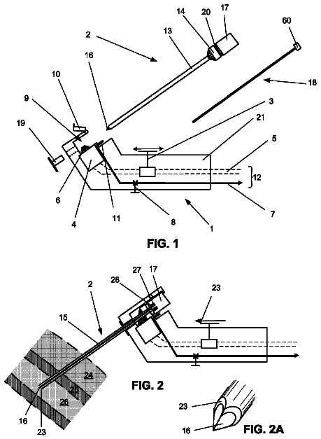
FIG. 1 is a schematic illustration of a delivery device in accordance with the principles of the present invention.
FIGS. 2A and 2B show actuator unit including metering valves for use in a foam delivery device according to one or more embodiments of the present invention.
FIG. 3 is a perspective view of a tube for use in the delivery device according to one or more embodiments of the present invention.
FIGS. 4A and 4B are side views of embodiments of the tube illustrating (A) threaded and (B) snap attachments for engagement with an actuator according to one or more embodiments of the present invention.
FIG. 5A is an upper view of a tube according to one or more embodiments of the present invention, and FIG. 5B is a lower view of the tube of FIG. 5A.
FIG. 6 is a diagram of a tube having a rapidly varying internal diameter in a step pattern.
FIG. 7A-7D are schematic illustration of an applicator tube having various internal configurations according to one or more embodiments.
FIGS. 8A-8C are side perspective views of the tube illustrating different location and arrangement of side wall apertures according to one or more embodiments of the present invention.
FIG. 9A is a schematic illustration of a syringe applicator tube having a tip aperture and FIG. 9B is a schematic illustration of an applicator tube having a tip aperture and multiple side wall apertures according to one or more embodiments of the invention.
FIG. 10 is a schematic side view of a syringe-applicator tube having a plurality of apertures of different diameters.
FIG. 11 presents a graph of the effect of tube internal diameter and propellant type on residual mass with EST-005 composition at tube lengths 100 mm (FIG. 11(a)) and 125 mm (FIG. 11(b));
FIG. 12 presents a graph of the effect of tube length and propellant type on residual mass with EST-005 composition;
FIG. 13 presents a graph of the effect if tube internal diameter, tube length, and propellant type on residual mass with EST-010 composition;
FIG. 14 presents a graph of the effect of tube length and propellant type on residual mass with EST-010 composition;
FIG. 15 shows the influence of tube dimensions on residual mass and jetting;
FIG. 16 presents a graph of the effect of tube internal diameter and propellant type on foam density with EST-010 composition;
FIG. 17 presents a bar chart of the effect of actuator size on mass released without an applicator tube;
FIG. 18 presents a bar chart of the effect of actuator size on mass released with an applicator tube having a large internal diameter without a hole and with one top hole;
FIG. 19 presents a bar chart of the effect of actuator size on mass released with an applicator tube having a large internal diameter and two holes of the same diameter;
FIG. 20 presents a bar chart of the effect of actuator size on mass released with an applicator tube having a large internal diameter and two holes of different diameter;
FIG. 21 presents a bar chart of the effect of actuator size on mass released with an applicator having a large internal diameter without a hole;
FIG. 22 presents a bar chart of the effect of actuator size on mass released with an applicator tube having medium internal diameter and two holes of the same diameter;
FIG. 23 presents a bar chart of the effect of actuator size on mass released with an applicator tube having medium internal diameter and two holes of different diameter;
FIG. 24 presents a bar chart of the effect of actuator size on mass released with an applicator tube having medium internal diameter a tip hole and no side hole;
FIG. 25 presents a bar chart of the effect of actuator size on mass released with an applicator tube having small internal diameter and two holes of the same diameter;
FIG. 26 presents a bar chart of the effect of actuator size on mass released with an applicator tube having medium internal diameter and two holes of different diameter;
FIG. 27 presents a bar chart of the effect of actuator size on mass released with an applicator tube having small internal diameter and two holes of same diameter plus an original hole; and
FIG. 28 presents a bar chart of the effect of actuator size on mass released with an applicator tube having medium internal diameter and two holes of different diameter plus an original hole.
FIG. 29 is a schematic illustration of the location and identification of tip and sidewall apertures introduced into the applicator tube according to one or more embodiments.
FIG. 30 is an photograph of a regular vaginal syringe applicator filled with gel or foam and introduced into the vaginal model.
FIG. 31A shows the gel distribution with a regular vaginal syringe applicator; and FIG. 31B shows the foam distribution with a regular vaginal syringe applicator.
FIGS. 32A and 32B show the distribution of (A) gel and (B) foam with the new vaginal applicator with side holes of same diameter (see FIG. 9B).
FIGS. 33A and 33B show the distribution of (A) gel and (B) foam with the new vaginal applicator with side holes of different diameter (see FIG. 10).
FIG. 34 is a schematic illustration of an applicator adapted for deep body cavity use attached to a flexible catheter by a connector and displays a wireless camera.
FIGS. 35A and 35B are (A) side and (B) front illustrations of a guard mounted on the applicator which can move up and down the length of the applicator by means of parallel indented channels.
FIGS. 36A and 36B are (A) side and (B) front illustrations of a guard mounted on the applicator which can move up and down the length of the applicator by means of a screw thread.
FIGS. 37A and 37B are (A) side and (B) front illustrations of an applicator with a bulged end, which may be coated to facilitate ease of removal and insertion.
FIG. 38 is a plot of % foam released from upper hole with medium actuator vs. ratio of upper aperture diameter/medium aperture diameter for determination of foam distribution from apertures.
FIG. 39 is a plot of % foam released from upper hole with large actuator vs. ratio of upper aperture diameter/medium aperture diameter for determination of foam distribution from apertures.
Description of the preferred embodiments
A device is described having a shape and dimensions which provide for optimized release of a foamable composition within a body cavity, providing optimal release of foam, continuity with minimal residual mass, low jetting and low degree of tailing.
Jets: Jetting occurs when the foamable composition is released with an unacceptably high ejection speed, and may result in discomfort to the user. Jets may be described as small aliquots of foam that are ejected discontinuously or erratically from the applicator in pulses with a high speed contrary to normal continuous single flow dispensing where a dose of foam flows from the applicator in a single portion. Different levels of jetting can be described and correspond to a low (+), medium (++), and high (+++) foam pulses. Note that jetting may be sensed by a patient and medium/high jetting can sometimes cause discomfort to the patient and is to be avoided in the device design.
Tails: Tailing occurs when a portion of the foamable composition is delivered as an initial pulse, followed by slower delivery of the remaining portion, such that the overall delivery time is increased.
Continuity: A continuous dispensing is when the foam is delivered from the applicator in a single portion. When there are interruptions in the foam flow from the applicator, the dispensing is described as discontinuous or with tailing. Foam is preferably dispensed in a single continuous flow.
Dispensing Time: Foam dispensing time is the period of time between actuator release and the end of foam flow from the applicator
Residual Mass: The amount of foam which stays within the applicator after the end of the foam flow and which is not released from the applicator to the target.
Noise: When foam is dispensed for example at a high flow speed or if high amounts of propellant are used release can be accompanied by a crackling or spitting like noise which can sometimes be quite loud enough to cause surprise.
The description continues in the full USPTO document.
 Lapsed, fee not paid4 drawings