 Lapsed, fee not paid8 drawings
Sports & Fitness · US 8,613,669 B1
Game controller with display and methods therefor
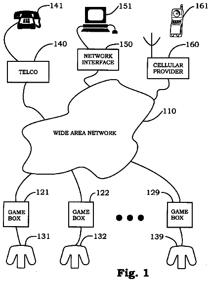
A game controller having a video display and messaging capability is provided.
US 8,616,385 B1 · Inventors: Doran; John
Sheet 1 of 6 from the published document. All sheets in the USPTO PDF
The present invention features a dugout organization system for baseball or softball equipment for use by a participant in a dugout. The system features a generally planar chain link fence panel located in an erect position having a plurality of formed chain link fence wires intertwined to form a mesh chain link fence surface. The system features a base member having a top attachment tongue that projects out and away from a base posterior surface. The top attachment tongue features a top attachment tongue first groove located on a top attachment tongue first side and a top attachment tongue second groove located on an opposing top attachment tongue second side. The base member flares from the top attachment tongue forming a first side shoulder on a base first side and a second side shoulder on a base second side and then tapers approaching a base bottom.
In many sports, various personal equipment components are required (or recommended) for participation or safety. For example, in baseball or softball, typical equipment includes items such as bats, balls, helmets, and gloves. In addition, various other personal items are often present at sporting events or practices such as sports drinks and towels. As a result, in a confined area such as a dugout, equipment and other items can easily become cluttered and disorganized leading to safety hazards and equipment damage when players run in and out of the dugout. The present invention features a dugout organization system for baseball or softball equipment for use by a participant in a dugout. Any feature or combination of features described herein are included within the scope of the present invention provided that the features included in any such combination are not mutually inconsistent as
All 6 drawing sheets from the published document, cropped to the drawing.
What the patent claimed, word for word. All of it is now free to use.
This application claims priority to U.S. non-provisional application Ser. No. 12/780,885 filed May 15, 2010, now U.S. Pat. No. 8,245,858, and U.S. non-provisional application Ser. No. 13/554,283 filed Jul. 20, 2012, now abandoned, the specifications of which are incorporated herein in their entirety by reference.
The present invention relates to sports organizing systems, or more specifically, organizing systems used in a dugout for baseball or softball.
In many sports, various personal equipment components are required (or recommended) for participation or safety. For example, in baseball or softball, typical equipment includes items such as bats, balls, helmets, and gloves. In addition, various other personal items are often present at sporting events or practices such as sports drinks and towels. As a result, in a confined area such as a dugout, equipment and other items can easily become cluttered and disorganized leading to safety hazards and equipment damage when players run in and out of the dugout. The present invention features a dugout organization system for baseball or softball equipment for use by a participant in a dugout.
Any feature or combination of features described herein are included within the scope of the present invention provided that the features included in any such combination are not mutually inconsistent as will be apparent from the context, this specification, and the knowledge of one of ordinary skill in the art. Additional advantages and aspects of the present invention are apparent in the following detailed description and claims.
The present invention features a dugout organization system for baseball or softball equipment for use by a participant in a dugout. In some embodiments, the system comprises a generally planar chain link fence panel located in an erect position. In some embodiments, the chain link fence panel comprises a plurality of formed chain link fence wires intertwined to form a mesh chain link fence surface. In some embodiments, the chain link fence panel comprises a plurality of generally diamond-shaped chain link fence openings located in a symmetrical pattern between the chain link fence wires. In some embodiments, each chain link fence opening is faced by a plurality of chain link fence wire interior surfaces.
In some embodiments, the system comprises a base member having a top attachment tongue located on a base posterior surface close to or on a base top. In some embodiments, the top attachment tongue projects out and away from the base posterior surface. In some embodiments, the top attachment tongue comprises a top attachment tongue first groove located on a top attachment tongue first side and a top attachment tongue second groove located on an opposing top attachment tongue second side. In some embodiments, a top attachment tongue neck is located between the top attachment tongue first groove and the top attachment tongue second groove on the top attachment tongue. In some embodiments, a top attachment tongue first tab is formed on the top attachment tongue via the top attachment tongue first groove and the top attachment tongue neck. In some embodiments, a top attachment tongue second tab is formed on the top attachment tongue via the top attachment tongue second groove and the top attachment tongue neck. In some embodiments, the first and second tabs originate from the center of the tongue and the first and second tabs project in opposite directions away from each other. In some embodiments, the first and second tongue grooves are on opposite sides of the tongue neck, and the opening of the first tongue groove opens in a first direction and the opening of the second tongue groove opens in a second direction, wherein the first and second directions are opposite each other.
In some embodiments, the base member flares from the top attachment tongue forming a first side shoulder on a base first side and a second side shoulder on a base second side. In some embodiments, the base member tapers on the base first side and the base second side approaching a base bottom. In some embodiments, a shelf is located on a base anterior surface. In some embodiments, a slotted bat hook having a bat hook first side and a bat hook second side is located on the base bottom.
FIG. 1 is a front perspective view of the base member of the present invention.
FIG. 2 is a rear perspective view of the base member of the present invention.
FIG. 3 is a top view of the base member of the present invention.
FIG. 4 is a side view of the base member of the present invention.
FIG. 5 is a front view of the base member of the present invention.
FIG. 6 is a side view of the base member of the present invention.
FIG. 7 is a rear view of the base member of the present invention.
FIG. 8 is a bottom view of the base member of the present invention.
FIG. 9 is a rear perspective view of the present invention.
FIG. 10 is a close up rear perspective view of a top attachment tongue and a bottom attachment projection of the present invention.
FIG. 11 is a view of an alternate embodiment of a bottom attachment projection of the present invention.
FIG. 12 is a view of an alternate embodiment of a bottom attachment projection of the present invention.
Following is a list of elements corresponding to a particular element referred to herein: 100 Dugout organization system 200 Chain link fence panel 210 Chain link fence wire 212 Chain link fence wire interior surface 220 Chain link fence panel surface 230 Chain link fence opening 300 Base member 310 Base member anterior surface 320 Base member posterior surface 330 Base top 340 Base first side 342 First side shoulder 350 Base second side 352 Second side shoulder 360 Base bottom 370 Base middle 400 Top attachment tongue 410 Top attachment tongue first side 412 Top attachment tongue first groove 414 First groove width 418 Top attachment tongue first tab 419 Width of top attachment tongue first tab 420 Top attachment tongue second side 422 Top attachment tongue second groove 424 Second groove width 428 Top attachment tongue second tab 429 Width of top attachment tongue second tab 430 Top attachment tongue neck 500 Bottom attachment projection 510 Bottom attachment projection side wall 512 First bottom attachment projection engagement interface 600 Shelf 610 Shelf side 620 Hook 630 Slotted bat hook 632 Slot 634 Slotted bat hook front edge 638 Slotted bat hook first projection 642 Slotted bat hook second projection 644 Bat hook first side 646 Bat hook second side 650 Projecting side panel 660 Aperture
Referring now to FIG. 1-12, the present invention features a dugout organization system
for baseball or softball equipment for use by a participant in a dugout. In some embodiments, the system
comprises a generally planar chain link fence panel
located in an erect position. In some embodiments, the chain link fence panel
comprises a plurality of formed chain link fence wires
intertwined to form a mesh chain link fence surface (220). In some embodiments, the chain link fence panel
comprises a plurality of generally diamond-shaped chain link fence openings
located in a symmetrical pattern between the chain link fence wires (210). In some embodiments, each chain link fence opening
is faced by a plurality of chain link fence wire interior surfaces (212).
In some embodiments, the system
comprises a base member
having a base anterior surface (310), a base posterior surface (320), a base top (330), a base first side (340), a base second side (350), and a base bottom (360). In some embodiments, the base member
comprises a top attachment tongue
located on the base posterior surface
close to or on the base top (330). In some embodiments, the top attachment tongue
projects out and away from the base posterior surface (320).
In some embodiments, the top attachment tongue
comprises a top attachment tongue first groove
located on a top attachment tongue first side
and a top attachment tongue second groove
located on an opposing top attachment tongue second side (420). In some embodiments, the top attachment tongue first groove
comprises a first groove width
for engaging one of the chain link fence wires (210). In some embodiments, the top attachment tongue second groove
comprises a second groove width
for engaging one of the chain link fence wires (210). In some embodiments, the first groove width
is not equal to the second groove width (424). In some embodiments, the first groove width
is equal to the second groove width (424).
In some embodiments, the width of the first tab 419 is wider than the width of the second tab 429. In some embodiments, the width of the first tab 419 is narrower than the width of the second tab 429. In some embodiments, the width of the first tab 419 is equal to the width of the second tab 429.
In some embodiments, a top attachment tongue neck
is located between the top attachment tongue first groove
and the top attachment tongue second groove
on the top attachment tongue (400). In some embodiments, a top attachment tongue first tab
is formed on the top attachment tongue
via the top attachment tongue first groove
and the top attachment tongue neck (430). In some embodiments, a top attachment tongue second tab
is formed on the top attachment tongue
via the top attachment tongue second groove
and the top attachment tongue neck (430).
In some embodiments, the base member
flares from the top attachment tongue
forming a first side shoulder
on the base first side
and a second side shoulder
on the base second side (350). In some embodiments, the base member
tapers on the base first side
and the base second side
approaching the base bottom (360).
In some embodiments, a shelf
is located on the base anterior surface (310).
In some embodiments, a slotted bat hook
having a bat hook first side
and a bat hook second side
is located on the base bottom (360). In some embodiments, the slotted bat hook
projects out and away from the base anterior surface (310). In some embodiments, the slotted bat hook
comprises a slot
located between the bat hook first side
and the bat hook second side
from a slotted bat hook front edge
for receiving a handle of a bat. In some embodiments, the slotted bat hook
comprises a slotted bat hook first projection
and a slotted bat hook second projection
for securely holding the bat.
In some embodiments, for use, the top attachment tongue
of the base member
is inserted into one of the chain link fence openings
and interlocked with the chain link fence panel
via the top attachment tongue first groove
and the top attachment tongue second groove
engaging the chain link fence wires (210). In some embodiments, the base posterior surface
rests against the chain link fence surface (220).
In some embodiments, a bottom attachment projection
is located on the base posterior surface (320). In some embodiments, the bottom attachment projection
projects out and away from the base posterior surface (320). In some embodiments, the bottom attachment projection
comprises a bottom attachment projection side wall
located thereon.
In some embodiments, the bottom attachment projection
is located at an offset from the top attachment tongue
to provide for engagement with a second one of the chain link fence openings
located beneath a first one of the chain link fence openings
upon installation of the top attachment tongue
into the first one of the chain link fence openings (230).
In some embodiments, when the bottom attachment projection
projects through the second one of the chain link fence openings
between two of the intertwined chain link fence wires (210), the bottom attachment projection side wall
engages at least one of the chain link fence wire interior surfaces
at a first bottom attachment projection engagement interface (512).
In some embodiments, the bottom attachment projection
is located close to a base middle
between the base first side
and the base second side (350). In some embodiments, the bottom attachment projection
is located close to the base first side
and a second bottom attachment projection
is located on the base posterior surface
close to the base second side (350). In some embodiments, the bottom attachment projection
is disposed proximal to a base middle
between the base first side
and the base second side (350). In some embodiments, the bottom attachment projection
is disposed proximal to the base first side
and a second bottom attachment projection
is disposed on the base posterior surface
proximal to the base second side (350).
In some embodiments, there are two or more bottom attachment projections
disposed on and project away from the base posterior surface (320).
In some embodiments, a fence mesh size measured from a first one of the chain link fence wires
to an opposing second one of the chain link fence wires
is between about 1 inch to about 21/8 inches.
In some embodiments, each chain link fence wire
size is between about 6 gage and about 12.5 gage.
In some embodiments, the shelf
comprises a shelf side
located on an edge of the shelf (600). In some embodiments, the shelf
is semicircular and designed to hold a sports drink or a water bottle.
In some embodiments, a hook
is located on the base first side (340). In some embodiments, the hook
projects outwardly away from the base anterior surface
and also upwardly in a direction of the base top (330).
In some embodiments, a hook
is located on the base second side (350). In some embodiments, the hook
projects outwardly away from the base anterior surface
and also upwardly in a direction of the base top (330).
In some embodiments, the base comprises a first hook
disposed on the base first side (340), wherein the hook
projects outwardly away from the base anterior surface
and also upwardly towards the base top (330), and a second hook
disposed on the base second side (350), wherein the hook
projects outwardly away from the base anterior surface
and also upwardly towards the base top (330).
In some embodiments, the base member
comprises a projecting side panel
located on the base first side (340). In some embodiments, the projecting side panel
projects out and away from the base member anterior surface (310). In some embodiments, the projecting side panel
projects straight. In some embodiments, the projecting side panel
flares outward.
In some embodiments, the base member
comprises a projecting side panel
located on the base second side (350). In some embodiments, the projecting side panel
projects out and away from the base member anterior surface (310). In some embodiments, the projecting side panel
projects straight. In some embodiments, the projecting side panel
flares outward.
In some embodiments, the base member
comprises an aperture
located therein. In some embodiments, the aperture
is used to secure the base member
to the chain link fence panel (200). In some embodiments, the aperture
is disposed close to or adjacent to the shelf (600).
The Holding Device
The holding device shall not be modified or re-worked to any other shape, including but not limited to, an oval, square, triangular, rectangular, circular, pentagon, hexagon, octagon, cube, trapezoid, triangle, sphere and/or any other possible shape modification.
Both front and back surfaces shall not be modified or re-worked to any other shape, including but not limited to, oval, square, triangular, rectangular, circular, pentagon, hexagon, octagon, cube, trapezoid, triangle, sphere and/or any other possible shape modification.
First side edges and second side edges shall not be modified, re-worked, extended or reduced to any other shape, including but not limited to, small, medium, large or height and lengths nor thinner or thicker.
Side edges shall not be modified, re-worked, extended or reduced to any other shape, including but not limited to, small, medium, large or height and lengths nor thinner or thicker.
The holding device platform shah not be modified, re-worked, extended or reduced to any other shape, including but not limited to, small, medium, large or height and lengths nor thinner or thicker.
The extension platform from the front of the base of the bottle holder shall not be modified, re-worked, extended or reduced to any other shape, including but not limited to, oval, square, triangular, rectangular, circular, pentagon, hexagon, octagon, cube, trapezoid, triangle and sphere to any other size of height and lengths nor thinner or thicker or extended from middle area.
The first hook extended to the first side edge to hold first objects such as a helmet, glove, jacket or visor to of the base shall not be modified, re-worked, extended or reduced to any other shape, including but not limited to, heights, lengths, widths or extend outwardly or inwardly. A second hook from second side edge to hold a second object such as a helmet, glove, jacket or visor of the base shall not be modified, re-worked, extended or reduced to any other shape, including but not limited to, heights, lengths, widths or extend outwardly or inwardly.
A two-prong bracket function to hold a fourth object extended outwardly from the bottom edge of the base of to hold a bat shall not be modified, re-worked, extended or reduced to any other shape, including but not limited to, an oval, square, triangular, rectangular, circular, pentagon, hexagon, octagon, cube, trapezoid, triangle, sphere and/or any other possible shape modification and shall not be modified to any other shape, including but not limited to, any other form or sizes small, medium, large or height and lengths nor thinner or thicker.
The slot is between the two prong brackets. The slot shall not be modified, re-worked, extended or reduced to any other shape, including but not limited to, various sizes of shapes, oval, square, triangular, rectangular, circular, pentagon, hexagons, octagon, cube, trapezoid, triangles and sphere and shall not be changed in any form or sizes small, medium, large or height and lengths nor thinner or thicker to a accommodate various objects.
The feature that extends from the base shall not be modified, re-worked, extended or reduced to any other shape including but not limited to, oval, square, triangular, rectangular, circular, pentagon, hexagons, octagon, cube, trapezoid, triangles and sphere shall not be modified to any other shape, including but not limited to, any other sizes small, medium, large or height and lengths nor thinner or thicker to a accommodate various objects.
The feature at the end of the base shall not be modified, re-worked, extended or reduced to any other shape, including but not limited to, oval, square, triangular, rectangular, circles, pentagon, hexagons, octagon, cube, trapezoid, triangles and sphere and shall not be modified to any other shape, including but not limited to, sizes small, medium, large or height and lengths nor thinner or thicker to a accommodate various objects.
The top mounting configuration attaches to and extends outwardly away from back surface of base (via a pivot component) with a wing to form a groove at a point where the first mounting component and the back surface of the base connect to the wings to be able to hang on a fence shall not be modified, re-worked, extended or reduced to any other shape, including but not limited to, oval, square, triangular, rectangular, circular, pentagon, hexagons, octagon, cube, trapezoid, triangles and sphere and shall not be modified, re-worked, extended or reduced to any other shape, including but not limited to, sizes small, medium, large or height and lengths nor thinner or thicker flat surface with wings.
The second mounting component is V shaped and shall not be modified, re-worked, multiplied, moved to different locations, extended or reduced to any other size shape, including but not limited to, oval, square, triangular, rectangular, circular, pentagon, hexagon, octagon, cube, trapezoid, triangles, sphere, sizes small, medium, large or height and lengths nor thinner or thicker on the back of the surface or in the back of extension.
A feature that supports both sides of another feature shall not be modified, re-worked, extended or reduced to any other shape, including but not limited to, oval, square, triangular, rectangular, circular, pentagon, hexagons, octagon, cube, trapezoid, triangles and sphere and shall not be modified or re-worked to any other shape, including but not limited to, sizes small, medium, large or height and lengths nor thinner or thicker to a accommodate various objects.
As used herein, the term "about" refers to plus or minus 10% of the referenced number.
The disclosures of the following U.S. Patents are incorporated in their entirety by reference herein: U.S. Patent Pub. No. 2006/0086878; U.S. Pat. No. 6,695,155; and U.S. Pat. No. 3,653,624.
Various modifications of the invention, in addition to those described herein, will be apparent to those skilled in the art from the foregoing description. Such modifications are also intended to fall within the scope of the appended claims. Each reference cited in the present application is incorporated herein by reference in its entirety.
Although there has been shown and described the preferred embodiment of the present invention, it will be readily apparent to those skilled in the art that modifications may be made thereto which do not exceed the scope of the appended claims. Therefore, the scope of the invention is only to be limited by the following claims. Reference numbers recited in the claims are exemplary and for ease of review by the patent office only, and are not limiting in any way. In some embodiments, the figures presented in this patent application are drawn to scale, including the angles, ratios of dimensions, etc. In some embodiments, the figures are representative only and the claims are not limited by the dimensions of the figures. In some embodiments, descriptions of the inventions described herein using the phrase "comprising" includes embodiments that could be described as "consisting of", and as such the written description requirement for claiming one or more embodiments of the present invention using the phrase "consisting of" is met.
The reference numbers recited in the below claims are solely for ease of examination of this patent application, and are exemplary, and are not intended in any way to limit the scope of the claims to the particular features having the corresponding reference numbers in the drawings.
About 3,721 words. The USPTO PDF has it with every drawing.
Fees are due 3.5, 7.5 and 11.5 years after grant. This patent expired on December 31, 2025, so the fee marked "not paid" was the one that went unpaid.
Dugout organization system
Filed May 2013 · granted Dec 2013Earlier publications, parents and continuations. None of them can still be enforced, or this patent would not be listed.
Prior art cited by the examiner or applicant. Useful when you check your own idea for novelty.
Everything on this page comes from the documents linked above.


