 Lapsed, fee not paid16 drawings
Industrial Equipment · US 8,615,879 B2
Positioning method
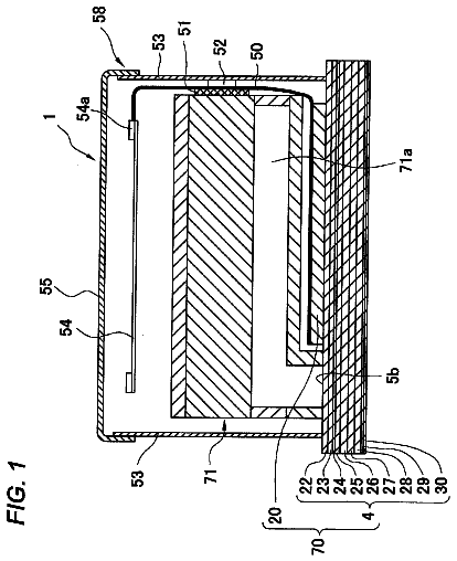
A method of making an electronic droplet discharge head includes positioning a channel forming member and an actuator unit.
US 8,615,930 B2 · Assignee: VKR Holding A/S · Inventors: Ryberg; Jesper et al.
Sheet 1 of 7 from the published document. All sheets in the USPTO PDF
The lifting device comprises abiased slide shoe adapted to be slidable with respect to a member of an openable structure, a lifting arm having two ends, one end adapted to be pivotally connected with a member of the structure and the other end associated with said slide shoe, and a braking device comprising at least one brake shoe slidable on a respective brake face of said lifting device, said braking device modulating the force resulting from the bias on said biased slide shoe. An adjusting device is adapted to adjust said progressive modulation of said force resulting from the bias on said biased slide shoe, and comprises a manipulation member, which when manipulated by a user activates said adjusting device to adjust a brake force of said brake shoe exerted on said brake face in a given position of said brake shoe.
Openable structures of the mentioned kind are typically in the form of for example top-hung windows installed in inclined surfaces, e.g. a roof of a building, the first member being a side sash member, and the second member being a side frame member of said window, or vice versa. A respective lifting device with a spring-biased slide shoe connects a respective side frame member and a respective sash side member on each side of the window. It is an aim in such windows to ensure that the force needing to be exerted by a user on the window sash when opening or closing of the window does not vary too much during the travelled path of the window sash, no matter of the roof inclination of the roof in which the window is installed and no matter variance of the weight of the window sash. The window sash weight may vary due to for example installation of optional accessories such as miscellaneous
1 of 7 drawing sheets so far from the published document, cropped to the drawing. Every sheet is in the USPTO PDF.
What the patent claimed, word for word. All of it is now free to use.
Openable structures of the mentioned kind are typically in the form of for example top-hung windows installed in inclined surfaces, e.g. a roof of a building, the first member being a side sash member, and the second member being a side frame member of said window, or vice versa. A respective lifting device with a spring-biased slide shoe connects a respective side frame member and a respective sash side member on each side of the window. It is an aim in such windows to ensure that the force needing to be exerted by a user on the window sash when opening or closing of the window does not vary too much during the travelled path of the window sash, no matter of the roof inclination of the roof in which the window is installed and no matter variance of the weight of the window sash. The window sash weight may vary due to for example installation of optional accessories such as miscellaneous screening devices, e.g. blackout curtains, some of which can be installed on mounted windows. In an attempt to alleviate this, applicant's EP 0 733 146 A suggests to provide an adjustable auxiliary spring in the lifting device to increase the spring bias within certain opening angles in windows mounted in roofs with certain roof inclinations.
The biased slide shoe of such lifting devices is mounted on and moves in parallel with or along either the side frame member or the side sash member. The slide shoe typically slides in a guidance mounted on the respective sash or frame member. The slide shoe is typically biased by means of a spring arrangement located in parallel with the respective sash or frame member, and pivotally connected to a lifting arm, the other end of which is pivotally connected with the other of the side sash member or side frame member. During opening and closing of the window the slide shoe slides in the guidance, providing a frictional braking force normal to a guidance bottom face, which in turn allows for the window to be placed in positions between fully opened and fully closed. When the window is opened, the lifting arm moves from a position near parallel with the frame or sash member on which the guidance is mounted to a position with an angle to both of these. In the angled position the frictional force exerted by the slide shoe on the guidance, and hence the braking effect, is inherently somewhat larger. Conversely, because the frictional force from the slide shoe normal to the guidance bottom face decreases during closing of the window, in a near-closed position of the window the braking effect is lower, making the window sensitive to influences such as wind forces in the near closed position. Thus, it is also an aim in such windows that with any roof inclination and weight of optional accessories mounted on the window sash the frictional or braking forces working during operation are such that the window can be firmly positioned in any opening degree, i.e. without the risk of sliding out of position because of for example gravitational or wind-induced forces exerted on the movable part of the window.
EP 1 052 342 B suggests as a solution to the latter problem a lifting device, in which a braking effect of a braking device is adjustable by means of a threaded bolt. The threaded bolt adjusts the force exerted by two lateral brake shoes on respective lateral brake faces of a guidance of the lifting device. This makes it possible to add a constant braking effect exerted in the entire path between fully opened and fully closed positions of the window, this added braking effect not being dependant on the bias on the slide shoe or the position of the window. If this braking device is adjusted to be able to hold the movable window part in a near-closed position, the accumulated braking effect is larger than desired in positions of larger opening angles, making it too hard for a user to bring the window from one position to another within these angles. Further, this braking device is subjected to wear and frequently needs to be replaced or readjusted.
A lifting device according to the introductory part of claim 1 and suggesting another solution to the problem of providing a suitable braking force in all positions of the window is known from applicant's EP 1 873 323 A. In this lifting device, the slide shoe comprises a braking device, which modulates a force resulting from the bias on the slide shoe in variation of a magnitude of said force, i.e. in variation of the path of the slide shoe. This provides for a path-dependent braking effect, which can be arranged to ensure that the braking effect is greater within the opening angles in which it is needed (i.e. near-closed window). The braking device comprises a linkage mechanism having two brake members connected with each other by a link extending at an angle with respect to a guidance portion forming at least one face in contact with a respective brake member. However, a window provided with this lifting device is only suitable with windows mounted in roofs with a certain interval of roof inclination angles and with window sashes of a certain weight.
DE 2 337 459 A discloses a lifting device in which a brake faces of a guidance, on which a slide shoe slides, are provided converging against each other along the path of the slide shoe. This provides a comparable braking effect as is disclosed in EP 1 873 323 A.
Thus, despite of these prior art solutions somewhat alleviating the mentioned problems, a need for further improving the ability of such a lifting device to adjust to different installation situations of an openable structure, such as a roof-mounted window, continues to exist. Further, lifting devices taking up less space, providing less wear and being cheaper to manufacture are desired.
With this background it is an object of the first aspect of the present invention to improve a lifting device of the kind mentioned in the introduction with respect to flexibility regarding different installation conditions as well as wear resistance and manufacturability.
This object is met by providing a lifting device adapted to be mounted in an openable structure for assisting in opening a first member of the structure relative to a second member of the structure, comprising a biased slide shoe adapted to be slidable with respect to the second or first member of said structure, a lifting arm having two ends, one end adapted to be pivotally connected with the first or second member of the structure and the other end associated with the slide shoe, and a braking device comprising at least one brake shoe slidable on a respective brake face of the lifting device, the braking device modulating a force resulting from the bias on the biased slide shoe in variation of a magnitude of the force. The lifting device is provided with an adjusting device adapted to adjust modulation of the force when the lifting device is in a mounted position on the openable structure, the adjusting device comprising a manipulation member, which when manipulated by a user, activates the adjusting device to adjust a brake force of the brake shoe exerted on the brake face in a given position of the brake shoe.
Hereby, it is possible for a user, an operator or a window installer to adjust a modulated braking device of a given lifting device of for example a certain window to a certain inclination of a roof, in which the window is or is to be mounted, or to a certain weight of the window sash including any optional accessories.
Thus, it is for example possible to adjust the braking effect such as to be larger at near-closed positions of the window, but smaller at larger opening angles, maintaining the advantages of the prior art braking devices. If the window is installed in a roof of greater inclination, and/or if the weight of the window sash including accessories is small, the gravitational forces in near-closed positions are smaller, and the braking device can be accordingly adjusted to provide a smaller braking effect. If the window is installed in a roof of smaller inclination, and/or if the weight of the window sash including accessories is greater, the gravitational forces in near-closed positions are greater, and the braking device can be adjusted to provide a greater braking effect. In both cases, the braking device can be adapted to progressively get smaller when the window is moved to larger opening angles in which the slide shoe provides a greater braking effect and the need for additional braking is smaller.
With the lifting device according to the first aspect of the invention it is thus possible for a larger number of inclination angles of the surface in which the openable structure is to be mounted within all opening angles to provide a suitable, near-constant value of the force to be exerted by user on the window in order to change its position. And the same is the case regarding the weight of the window sash including any accessories.
Furthermore, should the braking characteristics of the braking device change in the lifetime of the window, e.g. due to wear of a braking shoe, it is possible for a user to readily manipulate the manipulation member of the adjusting device to adjust the braking effect accordingly without having to separate any parts from or exchange any parts of the window. The same is the case should it be desired to remount the window in a roof of another inclination or to install or uninstall any accessories, such as a screening device.
In a preferred embodiment said adjusting device is adapted to modulate said force progressively, i.e. continuously decreasingly or increasingly, in relation to said magnitude of said force, preferably said force is modulated such as to vary substantially proportionally with said magnitude of said force. Hereby, the modulation can be adapted to correspond to the variation of the moment exerted by the window sash when the window is opened or closed. In some cases, instead of a proportional variation, an exponential or other non-linear variation might be preferable. In other embodiments the modulation is not necessarily progressive; it might vary between increasing and decreasing increments, for example in order to provide a stepwise positioning of the window sash in certain opening positions (corresponding to the embodiments shown in FIGS. 6 and 7 of EP 1 873 323 A).
In another preferred embodiment said adjusting device comprises an abutment member with a slide face abutting a corresponding slide face of said brake shoe, at least one of said slide faces being inclined with respect to a sliding direction of said slide shoe. In a development of this embodiment said spring arrangement comprises a helical main spring with a spring rod extending there-through and providing said brake face, one of said abutment member and said brake shoe being axially movable with a first end of said helical main spring, and the other being adapted to be axially fixed in relation to that of said first and second members with respect to which said biased slide shoe is adapted to be slidable such that movement of said slide shoe in relation to said first or second member of said structure causes said slide face of said abutment member to slide on said slide face of said brake shoe, thus providing said modulation, said adjusting device being adapted to adjust an inclination of said inclined slide face. This provides a small, wear-resistant and efficient braking device of which the modulation can be easily adjusted. Further, this embodiment provides more flexibility in positioning of the braking device, making it possible to position the braking device anywhere in the length direction of the spring rod. In a further development said brake shoe comprises at least two brake shoe segments abutting different brake face segments of said spring rod, each said brake shoe segment communicating with a different respective segment of said inclined slide surface, said adjusting device being adapted to adjust said brake shoe segments towards each other such as to adjust an inclination of said inclined surface segments. The provision of at least two brake shoe segments working in different directions enhances the stability and reliability of the lifting device, and reduces wear. Furthermore, the adjusting device can be readily manufactured and installed.
In a further embodiment said adjusting device comprises an adjustment member, said adjustment member being deformable or angularly displaceable on activation of said adjusting device. In a development of this embodiment said adjustment member is in the form of a guidance portion forming said brake face. This is especially advantageous in cases in which the braking device is of the type comprising a linkage mechanism having two brake shoes connected with each other by a link extending at an angle with respect to said guidance portion in contact with a respective brake shoe. In the case of the previously mentioned embodiment comprising such an abutment member, said adjustment member and the abutment member are preferably integral, i.e. one and the same member.
In another embodiment said braking device comprises a linkage mechanism having two said brake shoes connected with each other by a link extending at an angle with respect to a guidance portion forming said brake face in contact with a respective brake shoe, said adjusting device being adapted to adjust a length of said link. This provides an alternatively adjustable braking device of the type comprising a linkage mechanism.
In another embodiment said braking device comprises two laterally projecting said brake shoes abutting a guidance portion forming said brake face, said adjusting device being adapted to be inserted between said brake shoes to push them away from each other in order to adjust said brake force of said brake shoe exerted on said brake face. In a development of this embodiment said braking device comprises an abutment member with respective slide faces abutting corresponding respective slide faces of said laterally projecting brake shoes, at least one of said slide faces being inclined with respect to a sliding direction of said slide shoe, said abutment member being connected to said spring arrangement such that movement of said slide shoe in relation to said first or second member of said structure causes said slide face of said abutment member to slide on said slide faces of said brake shoes, thus modulating a force of said brake shoe exerted on said guidance portion. This provides a braking device, which can be included as part of the slide shoe.
In another embodiment said adjusting device comprises a threaded member, such as a screw, which when the manipulation member in the form of a head or like of said threaded member is activated adjusts said modulation. Hereby, a user can easily activate the adjusting device directly with by hand or with a screwdriver or like tool. Instead of a threaded member a tapered or wedge-shaped member, for example, can be applied, wherein the member may comprise barbs or the like in order to provide a stepwise adjustment and/or a snap locking engagement. Similarly, with a threaded member, a stepwise or continuous adjustment is possible.
The object of the second aspect of the present invention is to improve a lifting device of the kind mentioned in the introduction with respect to wear resistance, size, reliability and manufacturability.
This object is met by providing a lifting device adapted to be mounted in an openable structure for assisting in opening a first member of the structure relative to a second member of the structure, comprising a biased slide shoe adapted to be slidable with respect to the second or first member of the structure, the slide shoe being biased by means of a spring arrangement, a lifting arm having two ends, one end adapted to be pivotally connected with the first or second member of the structure and the other end associated with the slide shoe, and a braking device comprising at least one brake shoe slidable on a respective brake face of the lifting device, the braking device modulating a force resulting from the bias on the biased slide shoe in variation of a magnitude of the force. The lifting device is further provided with an abutment member with a slide face abutting a corresponding slide face of the brake shoe, at least one of the slide faces being inclined with respect to a sliding direction of the slide shoe, one of the abutment member and the brake shoe being connected to the spring arrangement, and the other being adapted to be axially fixed in relation to the slide shoe or in relation to that of the first and second members with respect to which the biased slide shoe is adapted to be slidable such that movement of the slide shoe in relation to the first or second member of the structure causes the slide face of the abutment member to slide on the slide face of the brake shoe providing a wedging effect between the brake shoe and abutment member, which modulates a brake force of the brake shoe exerted on the brake face dependent on a position of the slide shoe with respect to the second or first member of the structure.
The provision of such an abutment member provides more flexibility in positioning of the braking device. Also, it is possible to use a spring rod as the brake face, making it possible to position the braking device both anywhere in the length direction of the spring rod or in the slide shoe while maintaining the modulation of the braking force.
The lifting device is subjected to less wear and will continue to function properly even when moderately worn because the inclined face will better adjust to wear of the brake shoe or brake face. Further, it is more stable and reliable.
In a preferred embodiment said adjusting device is adapted to modulate said force progressively, i.e. continuously decreasingly or increasingly, in relation to said magnitude of said force, preferably said force is modulated such as to vary substantially proportionally with said magnitude of said force. Hereby, the modulation can be adapted to correspond to the variation of the moment exerted by the window sash when the window is opened or closed. In some cases, instead of a proportional variation, an exponential or other non-linear variation might be preferable. In other embodiments the modulation is not necessarily progressive; it might vary between increasing and decreasing increments, for example in order to provide a stepwise positioning of the window sash in certain opening positions (corresponding to the embodiments shown in FIGS. 6 and 7 of EP 1 873 323 A).
In another preferred embodiment said spring arrangement comprises a helical main spring with a spring rod extending there-through, said brake face being in the form of a surface of said spring rod. Said abutment member and said brake shoe are preferably positioned surrounding said spring rod, one of said abutment member and said brake shoe being axially movable with a first end of said main helical spring, and the other being adapted to be axially fixed in relation to that of said first and second members with respect to which said biased slide shoe is adapted to be slidable. This improves stability and reliability as well as reduces wear. In a further development of this embodiment said spring arrangement comprises a main helical spring and an auxiliary helical spring positioned in continuation of said main helical spring, said braking device being positioned between said main and auxiliary helical springs. Further, a more light-weight modulating braking device can be located in a position of the lifting device, in which typical windows have room to spare. This provides a lifting device, which is smaller. In another or further development said brake shoe comprises at least two brake shoe segments abutting different brake face segments of said spring rod, each said brake shoe segment communicating with a different respective segment of said inclined slide surface. The provision of at least two brake shoe segments working in different directions enhances the stability and reliability of the lifting device, and reduces wear. Furthermore, the adjusting device can be readily manufactured and installed.
In another preferred embodiment the inclination of said inclined slide surface is adjustable. This provides a lifting device with the advantages of adjusting the modulation of the braking device similar to the advantages described above with respect to the first aspect of the present invention. In a further development combining this and the previous embodiment said brake shoe segments each provide a segment of said inclined surface, said brake shoe segments being adjustable towards each other such as to enable adjustment of an inclination of said inclined surface segments, preferably at least one adjustment member, such as a threaded member, connects said brake shoe segments.
In another embodiment a first of said slide faces is linearly inclined, and the other curves convexly towards said first slide face, preferably said first slide face is cone-shaped, and said other slide face is dome-shaped. This ensures contact between the slide faces also in the event of wear in the braking device.
In another embodiment said braking device further comprises a second, similarly shaped, but reversed brake shoe positioned in axial continuation of the first brake shoe, said second brake shoe abutting a second, similarly shaped abutment member.
In a third aspect. the invention provides a window comprising a frame and a sash, characterized in that at least one lifting device is mounted on the frame and the sash.
In the following, the invention will be described in further detail with reference to the accompanying drawings, in which
FIG. 1 shows a perspective view of an embodiment of a top-hung window according to the third aspect of the present invention provided with a lifting device according to the first and/or second aspect of the invention, the window being in an open position;
FIG. 2 shows a perspective view of a first embodiment of a lifting device, this embodiment being according to the second aspect of the present invention;
FIG. 2a shows a perspective view of a detail of the lifting device of FIG. 2;
FIG. 2b shows a view similar to FIG. 2a with some parts of the lifting device hidden;
FIG. 3 shows a detail of a cross section taken along the line III-III in FIG. 2a;
FIG. 3a shows a perspective view of a braking device of the lifting device shown in FIG. 2 in a braking position;
FIG. 3b shows an exploded view corresponding to the view of FIG. 3a;
FIG. 4 shows an exploded perspective view of a braking device of a second embodiment of a lifting device, this lifting device being according to the second aspect of the present invention;
FIG. 5 shows a schematic exploded side view of a detail of a third embodiment of a lifting device, this lifting device being according to the second aspect of the present invention;
FIG. 6 shows a detailed perspective view of a braking device of a fourth embodiment of a lifting device, this embodiment being in accordance with both the first and second aspects of the present invention;
FIG. 7a shows a side view of the braking device of FIG. 6 adjusted to deliver a first braking effect;
FIG. 7b shows a view corresponding to that of FIG. 7a adjusted to deliver a second braking effect;
FIG. 8 shows a graph illustrating the relationship between force and distance travelled by parts of the lifting device as shown in FIG. 6 with varying values of the braking effect;
FIG. 9 shows a graph illustrating the relationship between force and distance travelled by parts of the lifting device as shown in FIG. 4;
FIG. 10 shows a schematic side view of a braking device of a fifth embodiment of a lifting device, this lifting device being in accordance with the first and second aspects of the present invention;
FIG. 11 shows a schematic side view of a detail of a sixth embodiment of a lifting device, this lifting device being in accordance with the first and second aspects of the present invention;
FIG. 12 shows a schematic side view of a detail of a seventh embodiment of a lifting device, this lifting device being in accordance with the first aspect of the present invention; and
FIG. 13 shows a schematic side view of a detail of an eighth embodiment of a lifting device, this lifting device being in accordance with the first aspect of the present invention.
FIG. 1 shows an openable structure in the form of a top-hung window comprising a first member in the form of a sash 1 and a second member in the form of a frame 2, the sash 1 being openable relative to the frame 2. The window is an embodiment of the window according to the third aspect of the present invention. The window is to be built into a surface (not shown), such as a roof, which may be inclined with respect to the horizontal as is suggested by the shown overall inclination of the window in FIG. 1. At the top of the frame 2 a hinge connection connects to the sash 1 carrying a glazing 3. The hinge connection will be described in further detail below. In a manner known per se, the frame 2 and sash 1 are each formed by four members of which the frame side member 2a, the sash side member 1a, and sash bottom member 1b are indicated. The sash 1 is openable with respect to the frame 2 as the sash 1 is moved from a closed position, in which e.g. the sash side member 1a is substantially parallel with the frame side member 2a, to an open position, in which the sash side member 1a forms an angle with the frame side member 2a. During this movement the sash 1 rotates about at hinge axis situated at the hinge connection at the top of the frame 2 and the sash 1. For assisting the movement of the sash 1 from the closed position to an open position, a lifting device generally designated 10 is mounted between the sash 1 and the frame 2 in a manner that will be described in further detail below. Other embodiments of the window are conceivable; e.g. the frame could be connected, at the top, with an intermediate frame constituting a support to a glass-carrying pivotal sash, which is able to rotate or pivot about a central hinge axis of the sash. The pivotal sash would, in this case, be connected with the intermediate frame by means of an upper closing means, the hinges at the top thus being in use at normal operation of the sash during opening and closing, while the pivoting function is mainly used for cleaning the outside of the glass.
FIG. 2 shows a detailed view of the lifting device 10 of the window shown in FIG. 1, the lifting device being according to a first embodiment of the second aspect of the present invention. The lifting device 10 comprises a first plate member 11 and a second plate member 12. The first and second plate members 11, 12 are connected with each other by means of a hinge 13. In the embodiment of the window shown in FIG. 1, the first plate member 11 is connected with the sash side member 1a, the second plate member 12 being connected with the frame side member 2a. A similar, mirror-inverted lifting device is correspondingly positioned at the opposite side members of the sash and frame. When the window is mounted in the surface (not shown), the second plate member 12 is connected with the stationary part of the structure in question, in casu the frame 2. In case the window is provided with an intermediate frame as described in the above, the connection between the intermediate frame and the glass-carrying sash could, e.g., be situated at the end of the first plate member 11 opposite relative to the hinge 13.
A lifting arm 14 of the lifting device 10 is at one end 14a pivotally connected by means of a hinge 15 with the first plate member 11 and at the other end 14b associated, i.e. connected by means of another hinge 16a, with a slide shoe 16. The slide shoe 16 is again connected to one end 17a of a spring rod 17, which will be described in further detail below. As will be described in more detail in connection with the below description of the operation of the lifting device, the slide shoe 16 is displaceable or slidable in a longitudinal direction of the frame side member 2a on a guidance portion 18 of the second plate member 12. However, in the present specification the term "slide shoe" should be interpreted to cover any element which is capable of performing such a displacement by means of any combination of movements including sliding, rolling etc.
As can be seen in FIG. 2, the guidance portion 18 is substantially U-shaped with a plate-shaped bottom part (not visible), which when mounted on the window extends along and coplanarly abuts a surface of the frame member 2a, and two side parts or legs extending normal to the bottom member. When the slide shoe 16 slides in the guidance portion 18, the weight of the sash 1 forces the slide shoe 16 against the bottom part providing a frictional braking contribution to the operation of the window as was described above in the introductory part of the description. Due to the angular movement of the lifting arm 14 this braking effect is near zero when the window is in a near-closed position and increases as the window is opened.
The slide shoe 16 is biased, the term "biased" in the present specification being given the meaning "influenced by any means providing a load on the slide shoe". This bias may be provided in any suitable manner. In the present embodiment, the bias is provided by a spring arrangement. The spring arrangement comprises a helical main spring 19 and an adjustable helical auxiliary spring 20 in a way generally similar to what is described in previously mentioned European patent No. 0 733 146 B1. Both springs 19, 20 are compression springs. The auxiliary spring 20 is embedded in a U-shaped spring housing portion 21 of the second plate member 12, the spring housing 21 provided in axial continuation of the guidance portion 18. The spring rod 17 extends from its first end 17a, which is fixed to the slide shoe 16, through central apertures of first the auxiliary spring 20 and then the main spring 19 to be fixed to a first, lower end 19a of the main spring 19. A description of further details and the functioning of a similar spring arrangement known per se can be found in previously mentioned European patent No. 0 733 146 B1.
A braking device 22 of the lifting device 10 is provided between the spring housing 21 and the main spring 19.
FIGS. 2a and 2b show an enlarged view of a detail of FIG. 2, the detail showing the position of the braking device 22. In FIG. 2b the second plate member 12 and the main spring 19 have been hidden for clarity reasons. In turn, FIG. 3 shows a detail of a cross section taken along the line III-III in FIG. 2a through the braking device 22. Furthermore, FIGS. 3a and 3b show the braking device 22 separated from the remaining parts of the lifting device 10, the latter figure showing an exploded view.
Referring to FIGS. 2a to 3b the braking device 22 comprises two brake shoes 23a, 23b, which are in the present case moulded integrally from a suitable friction-inducing material, preferably a plastics material such as POM9021C. The braking device 22 further comprises two abutment members 24a, 24b, which are in the present case manufactured from steel. Each brake shoe 23a, 23b comprises a respective slide face 25a, 25b, each abutting a corresponding respective slide face 26a, 26b of each abutment member 24a, 24b. Each of the slide faces 25a, 25b; 26a, 26b is inclined with respect to a sliding direction of the slide shoe 16, i.e. with respect to a longitudinal direction of the second plate member 12 and the frame side member 1a.
As can be seen from FIGS. 2 to 3a, in an installed position the abutment members 24a, 24b and the brake shoes 23a, 23b are positioned abutting each other in axial continuation of each other, each of them surrounding the spring rod 17. A first 24a of the abutment members is axially fixed in relation to the frame member 2a; more specifically the first abutment member 24a is axially restricted from movement in one axial direction by abutting an abutment part 27 of the spring housing 21, which is axially fixed in relation to the frame member 2a. The abutment part 27 is formed as part of a bottom part of the spring housing 21 having been bent upwards. The first abutment member 24a is restricted from movement in the opposite axial direction by abutting a first 23a of the brake shoes, the latter being forced against the first abutment member 24a because of the compressing spring force of the main spring 19 acting in this direction. In turn, the first brake shoe 23a is connected to the spring arrangement, more specifically it is axially movable with the first end 19a of the main spring 19 via a second 23b of said brake shoes and a second 24b of the abutment members. The second abutment member is connected to the main spring 19 via a connecting member 27a.
The slide faces 25a, 25b are each linearly inclined inwards forming respective concave cone-shaped slide faces. Correspondingly, the slide faces 26a, 26b curve convexly towards the slide faces 25a, 25b forming respective dome-shaped or hemispherical slide faces, cf. FIG. 3b. However, since the brake shoes 23a, 23b are made from elastic or flexible material, in use the slide faces 26a, 26b are forced towards taking on a linear shape against the slide faces 25a, 25b. The curved form in the relaxed state of the slide faces 26a, 26b ensures contact between the slide faces also in the event of wear in the braking device or in the case of smaller loads on the braking device 22.
Each of the brake shoes 23a, 23b further has respective inwardly facing faces 28a, 28b, which are parallel to and slidable on a brake face 29 provided as a surface of the spring rod 17. As is seen best in FIG. 3b the integrally formed brake shoes 23a, 23b are divided into three common brake shoe segments or portions 30a, 30b, 30c. The part of the slide face 25b provided by each portion 30a, 30b, 30c slides on a corresponding different segment of the slide face 26b, and the part of the inwardly facing face 28b provided by each portion 30a, 30b, 30c slides on or brakes against a corresponding different segment of the brake face 29 of the spring rod 17. The brake shoe 23a has similar, oppositely facing segments or portions working in a similar way against the slide face 26a. The three portions 30a, 30b, 30c are of the same shape and size and distributed evenly about the spring rod 17. The portions 30a, 30b, 30c are separated from each other by a small spacing, allowing the internal diameter of the brake shoe 23b to vary relative to the force exerted by the main spring 19 on the braking device 22, thus varying the force exerted by brake shoe 23b on the brake face 29 and, thereby, the braking effect of the braking device 22 on the lifting device 10. The distinct portions 30a, 30b, 30c are prevented against radially being completely separated from each other by means of a circumferentially extending, elastic O-ring 23c, e.g. made from rubber, which is loosely provided encircling the portions 30a, 30b, 30c. This is primarily of importance during assembly of the braking device 22.
Operation of the window of FIG. 1 is described in the following with reference to FIGS. 1 to 3b. From a closed position, the user operates an operating device (not shown) of the window. The operating device may be a handle connected with the sash bottom member 1b, and may include auxiliary opening means such as one or more pressure medium cylinders, chain operators or the like. In combination with the force, and hence moment, exerted by the user pushing the operating device outwards, the moment resulting from the weight of the sash 1 is overcome. During this movement, the slide shoe 16 at the connection between the spring rod 17 and the lifting arm 14 is displaced along the guidance portion 18 of the second plate member 12. All in all, this operation entails that the sash 1 is moved from a closed position to an open position as represented by FIG. 1.
During opening of the window, the sash member 1a is moved towards a larger angle in relation to the frame member 2a (FIG. 1). The first plate member 11 via hinge 15 pulls the first end 14a of the lifting arm 14 away from the second plate member 12, the lifting arm 14 pivoting about hinges 15, 16a (FIG. 2). This causes the slide shoe 16, and hereby the spring rod 17, to move in the direction of the main spring 19, i.e. inclined downwards in FIG. 1. Thus, the end 17b of the spring rod 17 releases the load on the end 19a of the main spring 19, and the main spring 19 is extended. As can be best understood from FIGS. 3 to 3b, the smaller load exerted by the main spring end 19b on the second abutment member 24b via connection member 27a relieves the axial load on the braking device 22. Hereby, the distance between abutment part 27 and connection member 27a grows, and the radial inwardly directed force exerted by the three portions 30a, 30b, 30c of brake shoes 23a, 23b (FIG. 3b) is relieved, the slide faces 25a, 25b sliding on the slide faces 26a, 26b, thus also relieving the resultant brake force against the brake face 29 of the spring rod 17. As a result, the brake force of the brake shoes 23a, 23b exerted on the brake face 29 is progressively modulated, i.e. progressively decreased or relieved, dependent on the position of the slide shoe 16 with respect to the frame member 2a.
Closing the window from the open position entails the opposite movements of the sash 1 and relevant parts of the lifting device. Hereby, the brake shoes 23a, 23b are wedged into the conical abutment members 24a, 24b because of the inclined mutual slide faces 25a, 25b; 26a, 26b. Thus, during opening of the window, the movement of the slide shoe 16 in relation to the frame member 2a can be said to provide a wedging effect between the brake shoes 24a, 24b and the abutment members 24a, 24b, this wedging effect being reversed during opening of the window.
Thus, during the opening and the closing of the window, the braking device 22 incorporated into the lifting device 10 modulates the force resulting from the bias acting on the slide shoe 16 of the lifting device 10.
The degree of modulation depends on an angle .alpha. of the cone of each abutment member 24a, 24b, cf. FIG. 3. In the embodiment shown the angle .alpha. is about 120.degree.. In other embodiments this angle .alpha. is adjustable such as to enable adjustment of the inclination of the inclined surface. This provides embodiments according to the second aspect of the invention, which are also in accordance with the first aspect of the invention. A more detailed description of a like embodiment is explained below with reference to FIGS. 6 to 7b.
In the embodiments of a lifting device shown in the following figures elements having the same or analogous function as in the embodiment described above carry the same reference numerals to which 100 has been added in each consecutive embodiment. Only differences with respect to the already described embodiment will be described.
FIG. 4 shows a braking device 122 of a second embodiment of a lifting device, this lifting device being according to the second aspect of the present invention. This braking device 122 can be positioned similarly to the braking device 22 described in connection with the first embodiment described above; i.e. surrounding the spring rod 17 for example between the main spring 19 and the auxiliary spring 20.
The description continues in the full USPTO document.
About 6,847 words. The USPTO PDF has it with every drawing.
Fees are due 3.5, 7.5 and 11.5 years after grant. This patent expired on December 31, 2025, so the fee marked "not paid" was the one that went unpaid.
LIFTING DEVICE
Filed Mar 2009 · published Feb 2012Lifting device adapted to be mounted in an openable structure
Filed Mar 2009 · granted Dec 2013Earlier publications, parents and continuations. None of them can still be enforced, or this patent would not be listed.
Prior art cited by the examiner or applicant. Useful when you check your own idea for novelty.
Everything on this page comes from the documents linked above.


