Lapsed, fee not paid9 drawings
Vehicles & Drones · US 8,615,335 B2
Progressive takeoff thrust ramp for an aircraft
A method is presented for controlling thrust generated by aircraft engines.
US 8,615,341 B2 · Assignee: Mitsubishi Electric Corporation · Inventors: Kitanaka; Hidetoshi
Sheet 1 of 5 from the published document. All sheets in the USPTO PDF
A propulsion control apparatus for an electric vehicle includes an inverter that converts a direct-current voltage into an alternating-current voltage, a power storage element, and a DCDC converter connected to the power storage element. The control apparatus further includes a circuit selector unit that selects any one of power supplied from an external power supply via a power collecting device and power supplied from the power storage element and outputs it to the inverter. A linkage control unit controls at least the DCDC converter and the circuit selector unit in a linked manner, in which the linkage control unit inputs control signals at least to the DCDC converter and the circuit selector unit and controls them in a linked manner, in accordance with each of a case where the electric vehicle travels by receiving power from the external power supply and a case where the electric vehicle travels by power from the power storage element.
Generally, an electric vehicle collects power from an overhead line via a power collecting device and travels by driving an electric motor by the power. In recent years, with improvement of a performance of a power storage element such as a secondary battery and an electric double layer capacitor, a development of a system in which these are mounted on the electric vehicle and the electric vehicle travels by driving the electric motor by power from the power storage element has been progressed. Conventionally, for example, in an electric vehicle control apparatus disclosed in Patent Document 1 described below, when power can be received from an overhead line (hereinafter, "in a normal condition"), an electric motor is driven by power from the overhead line similarly to a conventional electric railroad. On the other hand, when power cannot be received from the overhead line due to a power
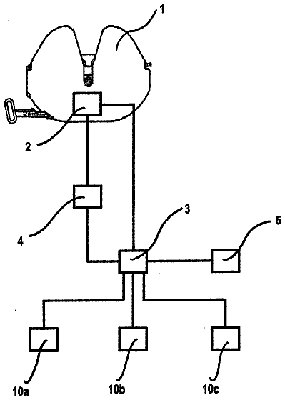
1 of 5 drawing sheets so far from the published document, cropped to the drawing. Every sheet is in the USPTO PDF.
What the patent claimed, word for word. All of it is now free to use.
The present invention relates to an electric vehicle control apparatus, particularly to a propulsion control apparatus for an electric vehicle that causes the electric vehicle to travel by power supplied from a power storage element when power cannot be received from an overhead line due a power interruption of the overhead line or a failure of a power collecting device.
Generally, an electric vehicle collects power from an overhead line via a power collecting device and travels by driving an electric motor by the power. In recent years, with improvement of a performance of a power storage element such as a secondary battery and an electric double layer capacitor, a development of a system in which these are mounted on the electric vehicle and the electric vehicle travels by driving the electric motor by power from the power storage element has been progressed.
Conventionally, for example, in an electric vehicle control apparatus disclosed in Patent Document 1 described below, when power can be received from an overhead line (hereinafter, "in a normal condition"), an electric motor is driven by power from the overhead line similarly to a conventional electric railroad. On the other hand, when power cannot be received from the overhead line due to a power interruption of the overhead line or a failure of a power collecting device (hereinafter, "in an emergency condition"), it is configured such that the electric vehicle can travel to a nearest station by driving the electric motor by power from a power storage element so that the electric vehicle does not get stuck on a track between stations.
A traveling example by this electric vehicle control apparatus is as follows. In the normal condition, a pantograph that is the power collecting device is raised, power is collected from the overhead line, and the electric motor is driven to cause the electric vehicle to travel as an existing electric railroad. In the emergency condition, the pantograph is lowered, and the electric vehicle travels by power from the power storage element. When power can be received from the overhead line, power from the overhead line is charged to this power storage element by charge control, so that power of a predetermined capacity is maintained.
Patent Document 1: Japanese Patent Application Laid-open No. 2006-014395
Problem to be Solved by the Invention
However, in the current technology level, both of an energy density and a power density of a power storage element are small. Thus, it is difficult to mount a power storage element, which is capable of exerting a performance equal to that of the case of receiving power from the overhead line, on the electric vehicle due to restriction on a mounting space, weight, and the like. Therefore, in the electric vehicle control device disclosed in the above-mentioned Patent Document 1, when the electric vehicle is caused to travel by power from the power storage element, supply power to the electric motor is limited (insufficient) compared to the case of travelling by receiving power from the overhead line. Thus, the performance, which the electric motor can exert, decreases and thus the vehicle speed decreases. Such a case is limited to the emergency condition, so that decrease in the vehicle speed itself is acceptable; however, problems to be described below mainly occur.
As a first problem, when the vehicle speed decreases, an inverter mounted on the electric vehicle control device is operated continuously in a region in which a switching loss is large, so that the inverter is overheated. To explain this in detail, generally, the inverter of the electric vehicle is driven in a multi-pulse PWM mode in which a switching frequency is around 1000 Hz from the start to the vehicle speed of around 1/4 of a maximum speed. Next, when the output frequency of the inverter becomes high, in order to avoid that the number of pulses included in a half cycle of the output voltage of the inverter decreases and a waveform distortion increases, the mode is switched to a synchronous pulse mode. At this time, the number of pulses included in the half cycle of the inverter output voltage is about 9, 5, and 3. These numbers of pulses are selected depending on the speed. After the vehicle speed reaches about 1/3 of the maximum speed, in order to maximize the output voltage of the inverter, the inverter is driven in a one-pulse mode. At this time, the number of pulses included in the half cycle of the inverter output voltage is one, which is a minimum, so that the switching loss can be minimized and a cooling fin of the inverter can be made small.
To explain with a specific vehicle speed, in a typical commuter train, the maximum speed is about 120 km/h, so that the commuter train is in the multi-pulse PWM mode from the start until the vehicle speed reaches to 30 km/h (1/4 of the maximum speed). Thereafter, the mode is switched to the synchronous pulse mode, and then is switched to the one-pulse mode at around 40 km/h (about 1/3 of the maximum speed).
However, when travelling by power from the power storage element, as described above, supply power to the electric motor is limited, so that the maximum speed is about 30 km/h. Therefore, the inverter is always switched in the multi-pulse PWM mode of around 1000 Hz and thus is operated continuously in the state where the switching loss is large. Thus, with the cooling fin of the inverter, which is designed considering an operation in the one-pulse mode, the cooling performance is insufficient.
As a countermeasure for the above problems, it is possible to specially design an inverter with enhanced cooling performance considering an operation at a low speed; however, it causes increase in weight, dimension, cost, and the like of the inverter device.
As a second problem, in order to cause the electric vehicle to travel, power needs to be supplied to loads such as a compressor that generates compressed air for driving a brake, a protection device, and a control device. In the normal condition, an auxiliary power device converts the power supplied from the overhead line into a low voltage power of around AC 400 V and around DC 100 V and supplies it to each load.
On the other hand, in the emergency condition, the auxiliary power device becomes unable to function, so that power cannot be supplied to each load. Particularly, the compressor stops operating, whereby the compressed air for brake cannot be ensured and the electric vehicle cannot travel.
For enabling the electric vehicle to travel, a configuration of causing the auxiliary power device to operate by power from the power storage element and supplying power to each load is considered; however, when the input voltage of the auxiliary power device falls outside the range of the voltage that is received from the overhead line in the normal condition, there is a problem that the auxiliary power device cannot maintain a specified output voltage and stops. Therefore, the auxiliary power device that is specially designed for accommodating both of the receiving voltage from the overhead line and the voltage from the power storage element is needed, which causes increase in weight, dimension, and cost.
The present invention has been made in view of the above, and an object thereof is to obtain a propulsion control apparatus for an electric vehicle capable of suitably causing the electric vehicle to travel by utilizing power from a power storage element in an emergency condition such as a power interruption of an overhead line while avoiding increase in weigh, dimension, and cost of an inverter that drives an electric motor and an auxiliary power device that performs power supply to a load.
Means for Solving Problem
To solve the problem described above and achieve the object, a propulsion control apparatus for an electric vehicle that includes an inverter that converts a direct-current voltage into an alternating-current voltage, a power storage element, and a DCDC converter connected to the power storage element, includes: a circuit selector unit that selects any one of power supplied from an external power supply via a power collecting device and power supplied from the power storage element and outputs it to the inverter; and a linkage control unit that controls at least the DCDC converter and the circuit selector unit in a linked manner, wherein the linkage control unit inputs a control signal at least to each of the DCDC converter and the circuit selector unit and controls them in a linked manner, in accordance with each of a case where the electric vehicle travels by receiving power from the external power supply and a case where the electric vehicle travels by power from the power storage element.
Effect of the Invention
In the propulsion control apparatus for the electric vehicle according to the present invention, the configuration is such that the circuit selector unit that selects one of the power supplied from the external power supply and the power supplied from the power storage element and supplies the power to the inverter, and the linkage control unit that controls the DCDC converter and the circuit selector unit in a linked manner are included, and the DCDC converter and the circuit selector unit are controlled in a linked manner, so that a travel control of the electric vehicle utilizing the power from the power storage element can be suitably performed in the emergency condition such as a power interruption of the overhead line while avoiding increase in weigh, dimension, and cost of the inverter and the auxiliary power device.
FIG. 1 is a diagram illustrating a configuration example of a propulsion control apparatus for an electric vehicle according to a present embodiment.
FIG. 2 is a diagram illustrating a configuration example of an inverter according to the present embodiment.
FIG. 3 is a diagram illustrating a configuration example of a DCDC converter according to the present embodiment.
FIG. 4 is a diagram illustrating a configuration example of a power storage element according to the present embodiment.
FIG. 5 is a diagram illustrating a configuration example of an auxiliary power device according to the present embodiment.
FIG. 6 is a diagram illustrating an example of a relationship between an inverter output voltage, a vehicle speed, and a pulse mode according to the present embodiment.
1 Overhead line
2 Power collecting device
3 Wheel
4 Rail
10 Open/close switch (open/close unit)
11 Power-collecting-state detecting unit
20 Auxiliary power device
21, 41, 45, 51 Reactor
22, 42, 52 Filter capacitor
23, 53 Inverter circuit
23a, 23b, 23c, 23d, 23e, 23f, 43a, 43b, 53a, 53b, 53c, 53d, 53e, 53f Semiconductor switching element
29 AC filter
30 Transformer
31 Load
40 DCDC converter
43 Switching circuit
54 Voltage detecting unit
59a Input-voltage monitoring unit
47 Current detector
48 DCDC converter control unit
50 Inverter
59 Inverter control unit
59b Protection operation unit
60 Power storage element
70 Circuit selector switch (circuit selector unit)
71 Electric motor
200 Linkage control unit
C1, C2, C3, C4, HC Control signal
An exemplary embodiment of a propulsion control apparatus for an electric vehicle according to the present invention will be explained in detail below based on the drawings. The invention is not limited to this embodiment.
Embodiment
FIG. 1 is a diagram illustrating a configuration example of a propulsion control apparatus for an electric vehicle according to the present embodiment. The propulsion control apparatus for the electric vehicle shown in FIG. 1 is configured to include as main components an auxiliary power device 20, a load 31, a DCDC converter 40, a circuit selector switch 70 that is a circuit selector unit, a power storage element 60, an inverter 50, and an electric motor 71. Moreover, a power-collecting-state detecting unit 11 that detects a connection state of an overhead line 1 and a power collecting device 2 or a state of the power collecting device 2, and an open/close switch 10 that is an open/close unit that separates the overhead line 1 from the power system of the propulsion control apparatus for the electric vehicle are included.
As shown in FIG. 1, the propulsion control apparatus for the electric vehicle receives power from the overhead line 1 that is an external power supply connected to a substation (not shown) via the power collecting device 2. The power supplied from the overhead line 1 is supplied to each of the auxiliary power device 20, the DCDC converter 40, and the circuit selector switch 70 via the open/close switch 10. FIG. 1 illustrates an overhead wire as the overhead line 1 and a pantographic one as the power collecting device 2; however, they are not limited thereto, and for example, a third rail and a power collecting device for a third rail used in a subway or the like can be used.
The auxiliary power device 20 is a device that converts power (typically, about DC 600 V to 3000 V that is a voltage of the overhead line 1) received between input terminals P-N from the power collecting device 2 or from the DCDC converter 40 into a low voltage power (typically, about AC 400 V or DC 100 V) and outputs it, and the output thereof is connected to the load 31. FIG. 1 illustrates only the form of outputting a three-phase AC, in which output terminals of the auxiliary power device 20 are U-V-W; however, a plurality of output systems including a DC output is typically present, thus enabling to accommodate various forms of power.
The load 31 is a compressor that generates an air source for a brake of the electric vehicle, a protection device, a control device, an air conditioning, an in-vehicle illumination, and the like, and operates by a low voltage power output from the auxiliary power device 20. The sum of these loads is, for example, about 400 kW in an example of a 10-car commuter train. Among them, the sum of important loads necessary for travel of the electric vehicle, such as a compressor that generates an air source for a brake, a protection device, a control device, and the like, is about 50 kW.
A linkage control unit 200 is configured such that a control signal HC is input from outside, and control signals C1, C2, C3, and C4 are output therefrom to the open/close switch 10, the circuit selector switch 70, the DCDC converter 40, and the inverter 50 to control these devices in a linked manner. For the linkage control unit 200, the configuration is illustrated in which the output control signals C1, C2, C3, and C4 are output to one open/close switch 10, one circuit selector switch 70, one DCDC converter 40, one the inverter 50, respectively; however, when the number of each of these devices is more than one, the configuration can be such that each of the control signal C1, C2, C3, and C4 is output to the corresponding devices the number of which is more than two. The control signal HC is a signal that is generated, for example, by a button operation by a driver of the electric vehicle or an external part such as an operation command center that is located outside the electric vehicle and instructs and manages an operation of a train, and is a signal generated when the electric vehicle cannot travel by the power from the overhead line 1 in the case of a power interruption of the overhead line 1 or a failure of the power collecting device 2. The control signal C1 is a signal that causes the open/close switch 10 to open and close, and the control signal C2 is a signal that performs a switching control of the circuit selector switch 70. Moreover, the control signal C3 is a signal that includes a control mode switching and operation and stop commands of a DCDC converter control unit 48 to be described later. Furthermore, the control signal C4 is a signal that performs a setting change of a protection setting value related to an input voltage of an inverter control unit 59 to be described later. The control signal C4 is not essential, which is described later.
The linkage control unit 200 can be provided inside the propulsion control apparatus for the electric vehicle, such as the inverter 50 and the DCDC converter 40, or can be provided outside the propulsion control apparatus for the electric vehicle. Moreover, the linkage control unit 200 can be such that all the functions are mounted on one device or the functions are divided into a plurality of groups to be mounted on each of a plurality of devices such as the inverter 50 and the DCDC converter 40. In other words, there is no restriction on a physical arrangement so long as the open/close switch 10, the circuit selector switch 70, the DCDC converter 40, and the inverter 50 can be controlled in a linked manner.
FIG. 2 is a diagram illustrating a configuration example of the inverter according to the present embodiment. The inverter 50 shown in FIG. 2 is configured to include an input filter including a reactor 51 and a filter capacitor 52, an inverter circuit 53 formed by a bridge circuit including semiconductor switching elements 53a to 53f, and the inverter control unit 59 including an input-voltage monitoring unit 59a and a protection operation unit 59b.
The inverter 50 receives a DC power output from the circuit selector switch 70 (see FIG. 1) via the input filter and converts the DC power into an AC power by the inverter circuit 53. The converted AC power is output from the terminals U-V-W. The electric motor 71 is connected to the terminals U-V-W of the inverter 50.
FIG. 2 illustrates a typical three-phase two-level PWM inverter circuit as the inverter circuit 53, and the operation thereof is a known technology, so that details thereof are omitted. Incidentally, the inverter circuit 53 is not limited to the three-phase two-level PWM inverter circuit, and, for example, the number of phases can be other than three phases and a three-level inverter circuit can be used.
A cooling method of the semiconductor switching elements 53a to 53f mounted on a cooling plate is as follows. For example, a cooling fin arranged at one end of a heat transport unit such as a heat pipe inserted into the cooling plate receives a relative wind of the electric vehicle. Heat generated from the semiconductor switching elements 53a to 53f is radiated from the cooling fin via the cooling plate and the heat transport unit. Consequently, the semiconductor switching elements 53a to 53f are cooled.
FIG. 3 is a diagram illustrating a configuration example of the DCDC converter according to the present embodiment. The DCDC converter 40 shown in FIG. 3 is configured to include an input filter including a reactor 41 and a filter capacitor 42, a switching circuit 43 formed by an arm circuit including a semiconductor switching element 43a and a semiconductor switching element 43b, a reactor 45, a current detector 47, and the DCDC converter control unit 48.
The DCDC converter 40 has a current control mode of causing the current of the reactor 45 detected by the current detector 47 to match a predetermined command value and a voltage control mode of causing the voltage of the filter capacitor 42 to match a predetermined command value, and is capable of switching between these modes by the above described control signal C3. Therefore, the DC power supplied via the input filter is converted into a voltage-variable DC power by the switching circuit 43 and the reactor 45 and is output from terminals P2-N.
Moreover, the DCDC converter 40 has a conversion capacity necessary for charging the power storage element 60. The conversion capacity of the DCDC converter 40 is determined based on a time required for the power storage element 60 in a state in which stored power has been used up is fully charged. For example, it is needed to complete charging in a few hours in view of an operation of the electric vehicle. If it is designed to be fully charged in 2 hours, the conversion capacity of the DCDC converter 40 is obtained by dividing the stored electric energy of the power storage element 60 by the charging time, i.e., 100 kWh/2 hours=50 kW.
Moreover, in the emergency condition, the DCDC converter 40 boosts the power supplied from the power storage element 60 to a value near the rated (nominal) voltage of the overhead line 1 or a value within the normal voltage variation range of the overhead line 1 and supplies it to the auxiliary power device 20. The capacity of the load 31 connected to the auxiliary power device 20 is determined to be about 50 kW assuming only important loads necessary for travelling. In other words, the capacity is about the same as the above described conversion capacity.
FIG. 3 illustrates a typical bidirectional step-down chopper circuit as the DCDC converter circuit, and the operation thereof is a known technology, so that detailed explanation is omitted. Incidentally, for the DCDC converter circuit, a plurality of circuit configurations is known other than this, and the configuration thereof is arbitrary so long as the similar function can be realized.
FIG. 4 is a diagram illustrating a configuration example of the power storage element according to the present embodiment. The power storage element 60 is formed by a power storage element such as a nickel-metal-hydride secondary battery, a lithium-ion secondary battery, and an electric double layer capacitor, and the type thereof is arbitrary. Moreover, the power storage element 60 is formed by series-parallel connecting a plurality of power storage cells 61, and can adjust a voltage between output terminals +/- by adjusting the number of the power storage cells 61 connected in series. Furthermore, the stored electric energy can be adjusted by adjusting the number of the power storage cells 61 connected in parallel. The type of the power storage cell 61 can be other than the above.
The power storage element 60 is designed by assuming to move an electric vehicle, which is a 10-car commuter train for example, about a few km to a nearest station in the emergency condition, and has the stored electric energy of about 100 kWh. Moreover, the voltage between the +/- terminals of the power storage element 60 is adjusted so that the inverter 50 can operate in a one-pulse mode at an operating speed, which is close to the travelling speed in the emergency condition, by adjusting the number of the power storage cells 61 connected in series.
Specifically, although it depends on the stored power capacity of the power storage element 60, when the rated (nominal) voltage of the overhead line 1 is 1500 V, the voltage between the +/- terminals of the power storage element 60 is set to 300 V to 750 V. When the rated (nominal) voltage of the overhead line 1 is 600 V, the voltage between the +/- terminals of the power storage element 60 is set to 120 V to 300 V. In other words, the voltage between the +/- terminals of the power storage element 60 is preferably set in the range of 20% to 50% of the rated (nominal) voltage of the overhead line 1. The relationship between the voltage between the +/- terminals of the power storage element 60, the vehicle speed, and the pulse mode is described later.
In the circuit selector switch 70, A side is connected to the power collecting device 2 side, B side is connected to the power storage element 60 side, and a common terminal C is connected to a P terminal of the inverter 50. A supply source of power can be switched by switching a connection point in the circuit selector switch 70, so that the inverter 50 can drive the electric motor 71 in a mode of operating by the power supplied from the power collecting device 2 or a mode of operating by the power supplied from the power storage element 60. The electric motor 71 is an AC electric motor such as a three-phase induction motor and a permanent-magnet synchronous motor, and the electric vehicle is caused to travel by driving a wheel 3 by the electric motor 71.
FIG. 5 is a diagram illustrating a configuration example of the auxiliary power device according to the present embodiment. The auxiliary power device 20 shown in FIG. 5 is configured to include an input filter including a reactor 21 and a filter capacitor 22, and an inverter circuit 23 formed by a bridge circuit including semiconductor switching elements 23a to 23f. Moreover, the auxiliary power device 20 includes an AC filter 29 and a transformer 30.
The auxiliary power device 20 receives a DC power output from the power collecting device 2 or from the DCDC converter 40 via the input filter and converts the DC power into an AC power by the inverter circuit 23. The converted AC power, after a switching ripple is removed by the AC filter 29, is insulated by the transformer 30, is adjusted to a predetermined voltage (typically, about AC 400 V), and is output to the load 31 from the terminals U-V-W.
FIG. 5 illustrates a typical three-phase two-level PWM inverter circuit as the inverter circuit 23, and the operation thereof is a known technology, so that details thereof are omitted. Incidentally, the inverter circuit 23 is not limited to the three-phase two-level PWM inverter circuit, and, for example, the number of phases can be other than three phases and a three-level inverter circuit can be used.
Next, the operation of the auxiliary power device 20 is explained with specific numerical values.
For example, in the case of the overhead line of which rated (nominal) voltage is 1500 V, the voltage of the overhead line 1 varies in the range of about 1000 V to 1800 V, so that the voltage between the input terminals P-N of the auxiliary power device 20 also varies similarly. This variation amount of the voltage is absorbed in the inverter circuit 23 that includes the semiconductor switching elements 23a to 23f. Specifically, when the input voltage of the auxiliary power device 20 is 1000 V that is a minimum value, the auxiliary power device 20 increases the modulation factor of the inverter circuit 23 to a value near a maximum value, and when the input voltage is 1800 V that is a maximum value, the auxiliary power device 20 reduces the modulation factor of the inverter circuit 23, thereby performing control of maintaining the input-side (primary-side) voltage of the transformer 30 to be constant. The input side (primary side) voltage of the transformer 30 is about 600 V and the output side (secondary side) voltage is about 400 V.
When the input voltage drops to less than 1000 V, the modulation factor of the inverter circuit 23 becomes a maximum value and cannot be increased over that value, so that the output voltage of the inverter circuit 23 drops in proportion to the drop of the input voltage. In other words, the input side (primary side) voltage of the transformer 30 cannot be maintained to a specified value (about 600 V in the above example) and the output voltage to the load 31 also cannot be maintained to a specified value (about 400 V in the above example). Consequently, a not-shown protection function is activated and the auxiliary power device 20 stops.
Even when the input voltage drops to less than 1000 V, in order to maintain the output voltage to the load 31 to the specified value (about 400 V in the above example), it is needed to set the input side (primary side) voltage of the transformer 30 to a low voltage, for example, 500 V, to have a margin from the upper limit in the modulation factor of the inverter circuit 23. However, if the input side (primary side) voltage of the transformer 30 is set low, a current value becomes large for obtaining the same power, so that volume, weight, and cost of the semiconductor switching elements 23a to 23f and the transformer 30 increase. In the configuration of the present embodiment, stoppage of the auxiliary power device 20 can be avoided without considering such special design.
An N terminal of the auxiliary power device 20, an N terminal of the DCDC converter 40, one terminal of the power storage element 60, and an N terminal of the inverter 50 are each connected to the wheel 3, so that a return current output from each terminal is returned to a substation (not shown) via a rail 4.
Among the above respective components, a plurality of arbitrary components can be regarded as the propulsion control apparatus for the electric vehicle. Alternatively, each of the components can be regarded as the propulsion control apparatus for the electric vehicle.
In FIG. 1, each component of the auxiliary power device 20, the DCDC converter 40, the power storage element 60, the inverter 50, the electric motor 71, and the like is illustrated as one device; however, each of them can be divided into a plurality of units.
Next, a rated capacity of each device is explained with a typical commuter train having about 10 cars as a model. Even if the number of cars is changed, the relative relationship between capacities of respective components is substantially maintained.
As the rated (nominal) voltage of the overhead line 1, DC 600 V, DC 750 V, DC 1500 V, DC 3000 V, and the like are mainly present. As described above, the load capacity is about 400 kW in total. Therefore, the conversion capacity of the auxiliary power device 20 is about 400 kW. As described above, the sum of the important loads is about 50 kW.
The electric motor 71 is about 150 kW per unit, and four electric motors 71 are provided in one electrically-operated car. In the case of a 10-car train, about four electrically-operated cars are present, so that the number of the electric motors 71 mounted on the train is 16. Thus, the sum of the outputs of the electric motors 71 is about 2400 kW.
The power-collecting-state detecting unit 11 detects the connection state of the overhead line 1 and the power collecting device 2 or the state of the power collecting device 2. The detected state is input to the linkage control unit 200. The linkage control unit 200 starts the operation of starting the DCDC converter 40, boosting the voltage from the power storage element 60, and feeding power to the auxiliary power device 20 after checking that the power collecting device 2 is surely separated from the overhead line 1. With this operation, the voltage boosted in the DCDC converter 40 can be prevented from flowing into the overhead line 1 via the power collecting device 2, so that when there is a failure point such as a short-circuit in the overhead line 1, it is prevented that the voltage boosted in the DCDC converter 40 is applied to the failure point and the damage spreads.
The open/close switch 10 is disposed between the connection portions, to which the auxiliary power device 20 and the DCDC converter 40 are connected, and the power collecting device 2, and can separate the auxiliary power device 20 and the DCDC converter 40 from the power collecting device 2. The state of the open/close switch 10 is input to the linkage control unit 200. Under the condition that the open/close switch 10 is opened, the linkage control unit 200 starts the operation of starting the DCDC converter 40, boosting the voltage from the power storage element 60, and feeding power to the auxiliary power device 20. With this operation, the voltage boosted in the DCDC converter 40 can be prevented from flowing into the overhead line 1 via the power collecting device 2, so that when there is a failure point such as a short-circuit in the overhead line 1, it is prevented that the voltage boosted in the DCDC converter 40 is applied to the failure point and the damage spreads.
Generally a configuration is adopted in which four electric motors 71 are connected to each inverter 50 in parallel and each inverter 50 drives the four electric motors 71 collectively. Therefore, the conversion capacity of each inverter 50 is about 600 kW. Four inverters 50 are mounted on the electric vehicle having 10 cars.
As described above, the power storage element 60 has an electric energy of about 100 kWh by assuming to move the electric vehicle about a few km to a nearest station in the emergency condition. As described above, the conversion capacity of the DCDC converter 40 is 50 kW (100 kWh/2 hours).
In this manner, the output capacity of the DCDC converter 40 may be a capacity capable of supplying power to the important loads connected to the auxiliary power device 20 and may be smaller than the output capacity of the auxiliary power device 20. In the propulsion control apparatus for the electric vehicle illustrated in the present embodiment, the DCDC converter 40 can be configured as a small-capacity device, so that size and weight reduction and cost reduction of the propulsion control apparatus are possible.
Next, the operation of the propulsion control apparatus for the electric vehicle is explained. The operation in the normal condition is as follows. The circuit selector switch 70 selects the A side. The auxiliary power device 20 supplies power to the load 31 by the power supplied from the overhead line 1.
Meanwhile, the inverter 50 drives the electric motor 71 by the power supplied from the overhead line 1. As described above, the power supplied to the electric motor 71 is about 2400 kW in total. The DCDC converter 40 charges the power storage element 60 by the power supplied from the overhead line 1.
The operation in the emergency condition is as follows. The circuit selector switch 70 selects the B side. The DCDC converter 40 boosts the voltage from the power storage element 60 to a value near the rated (nominal) voltage of the overhead line 1 or within the normal voltage variation range of the overhead line 1 and supplies it to the auxiliary power device 20. The auxiliary power device 20 drives the load 31 by the power supplied from the DCDC converter 40. The power supplied to the load 31 is about 50 kW with which the important loads can be driven.
Meanwhile, the inverter 50 drives the electric motor 71 by the power supplied from the power storage element 60 without via the DCDC converter 40. The power that can be supplied to the electric motor 71 is typically about five times (500 kW) of a Wh capacity (100 kWh) of the power storage element 60 although it depends on the characteristics (power density) of the power storage element 60. Therefore, the power that can be supplied to the electric motor 71 is about 20% of the normal condition (2400 kW). In this case, the vehicle speed of the electric vehicle becomes low, and the acceleration and the maximum speed both show values lower than the normal condition; however, the electric vehicle can travel by the power supplied to the load 31 and the electric motor 71.
Next, the operation of the linkage control unit 200 is explained.
When the control signal HC to be input from outside is off, the electric vehicle determines that the electric vehicle can travel by receiving power from the overhead line 1 (normal condition), turns the open/close switch 10 on by the control signals C1 to C3, connects the circuit selector switch 70 to the A side, and operates the DCDC converter 40 in the current control mode of causing the current of the reactor 45 to match a predetermined command value. Moreover, setting of the protection setting value related to the input voltage in the inverter 50 is performed based on the control signal C4.
The inverter 50 includes the input-voltage monitoring unit 59a that monitors the input voltage (voltage of the filter capacitor 52) by using a voltage detecting unit 54. Moreover, the inverter 50 includes the protection operation unit 59b that stops the inverter 50 when the input voltage falls outside a specified range. When the electric vehicle travels by receiving power from the overhead line 1, the input-voltage monitoring unit 59a sets the specified range to about 1000 V to 1900 V in the case where the nominal voltage of the overhead line 1 is 1500 V.
With this configuration, the power from the overhead line 1 can be directly input to the inverter 50 and the auxiliary power device 20. Moreover, with the DCDC converter 40, the power storage element 60 can be charged to a predetermined value. Furthermore, when the voltage from the overhead line 1 is within the specified value, the inverter 50 can operate stably, and when the voltage from the overhead line 1 is out of the specified value, the inverter 50 can be stopped immediately.
When the control signal HC input from outside is on, the electric vehicle determines that the electric vehicle cannot travel by receiving power from the overhead line 1 (emergency condition), turns the open/close switch 10 off by the control signals C1 to C3, connects the circuit selector switch 70 to the B side, and operates the DCDC converter 40 in the voltage control mode of causing the voltage of the filter capacitor 42 to match a predetermined command value. The operation of the DCDC converter 40 is started under the condition that the open/close switch 10 is turned off. Moreover, setting change of the protection setting value related to the input voltage in the inverter 50 is performed based on the control signal C4.
As described above, the inverter 50 includes the input-voltage monitoring unit 59a, and when the electric vehicle travels by receiving power from the power storage element 60, the input-voltage monitoring unit 59a sets the specified range to about 400 V to 700 V in the case where the nominal voltage of the power storage element 60 is 600 V.
With this configuration, when the voltage of the power storage element 60 is within the specified value, the inverter 50 can operate stably, and when the voltage of the power storage element 60 is out of the specified value, the inverter 50 can be stopped immediately. Moreover, the power from the power storage element 60 can be directly input to the inverter 50. Therefore, the stored power of the power storage element 60 can be supplied to the electric motor 71 via the inverter 50 without loss. Moreover, the power from the power storage element 60 can be boosted to the predetermined value and supplied to the auxiliary power device 20 by the DCDC converter 40.
The configuration can be such that the protection setting values related to the input voltage set to the protection operation unit 59b and the input-voltage monitoring unit 59a are set independently in the inverter 50 and the protection setting value is not necessarily set based on the control signal C4. For example, the configuration can be such that the protection setting value is determined and set based on the average value of the input value.
The linkage control unit 200 is configured to output a control command to an air conditioner (not shown), which is in the power feeding range of the auxiliary power device 20 and mounted on the electric vehicle, and is preferably configured to, when the electric vehicle travels by the power from the power storage element 60, stops the air conditioner by outputting a stop command to the air conditioner. With this configuration, power consumption in the air conditioner can be reduced, so that the power from the power storage element 60 can be used maximally for traveling.
The description continues in the full USPTO document.
About 6,705 words. The USPTO PDF has it with every drawing.
Fees are due 3.5, 7.5 and 11.5 years after grant. This patent expired on December 24, 2025, so the fee marked "not paid" was the one that went unpaid.
PROPULSION CONTROL APPARATUS FOR ELECTRIC VEHICLE
Filed Oct 2008 · published Jul 2011Propulsion control apparatus for electric vehicle
Filed Oct 2008 · granted Dec 2013Earlier publications, parents and continuations. None of them can still be enforced, or this patent would not be listed.
Prior art cited by the examiner or applicant. Useful when you check your own idea for novelty.
Everything on this page comes from the documents linked above.