Technical field
This description relates to radio network control.
Background
High Data Rate (HDR) is an emerging mobile wireless access technology that enables personal broadband Internet services to be accessed anywhere, anytime (see P. Bender, et al., "CDMA/HDR: A Bandwidth-Efficient High-Speed Wireless Data Service for Nomadic Users", IEEE Communications Magazine, July 2000, and 3GPP2, "Draft Baseline Text for 1xEV-DO," Aug. 21, 2000). Developed by Qualcomm, HDR is an air interface optimized for IP packet data services that can deliver a shared forward link transmission rate of up to 2.46 Mbit/s per sector using only (1X) 1.25 MHz of spectrum. Compatible with CDMA2000 radio access (TIA/EIA/IS-2001, "Interoperability Specification (IOS) for CDMA2000 Network Access Interfaces," May 2000) and wireless IP network interfaces (TIA/EIA/TSB-115, "Wireless IP Architecture Based on IETF Protocols," Jun. 6, 2000, and TIA/EIA/IS-835, "Wireless IP Network Standard," 3.sup.rd Generation Partnership Project 2 (3GPP2), Version 1.0, Jul. 14, 2000), HDR networks can be built entirely on IP technologies, all the way from the mobile Access Terminal (AT) to the global Internet, thus taking full advantage of the scalability, redundancy and low-cost of IP networks.
HDR has been adopted by TIA (Telecommunications Industry Association) as a new standard in the CDMA2000 family, an EVolution of the current 1xRTT standard for high-speed data-only (DO) services, formally referred to as HRPD (High Rate Packet Data), also known as 1xEV-DO or IS-856.
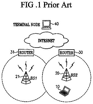
IS-856 systems are typically implemented using the radio access network architecture shown in FIG. 1. Here the Access Terminal (AT) 10 may be a laptop computer, a Personal Digital Assistant (PDA), a dual-mode voice/data handset, or another device, with built-in IS-856 support.
The entire administrative service area of a wireless access provider may be divided into one or more subnetworks (or subnets) 12, 14. Each subnet 12 includes a set of Radio Nodes (RN's) 16, 18 and one or more Radio Network Controllers (RNC) 20, 22. The RN's are connected to RNC's over a backhaul network 24. In existing 2G and 3G wireless networks, each RN is connected to only one RNC using dedicated leased lines or ATM permanent virtual circuits (PVC's). Further, RNC's are connected to each other using dedicated leased lines or ATM PVC's. In a new generation of IP-based radio access networks, the backhaul can be implemented using a shared IP or metropolitan Ethernet network which supports many-to-many connectivity between RN's and RNC's.
Each RNC typically controls 25-100 RN's. Each RN typically supports 1-4 carriers each of 1.25 MHz of bandwidth. Further, each cell area (not shown) is typically divided into multiple sectors (typically 3 or 6) and the RN has one radio transceiver 27 for each sector.
Each RNC is connected over an IP network 26 to one or more Packet Data Serving Node's (PDSN's) 28 (see TIA references cited earlier). The RNC communicates with the PDSN over a standard interface termed the R-P (Radio-Packet) interface 30. The R-P interface is further broken into two interfaces: the A10 interface used to carry data and the A11 interface used to carry signaling. A PDSN can be viewed as an edge router that supports mobility; it maintains link layer connectivity to AT's through the Access Network. The PDSN also interfaces to AAA servers 32 for Authentication, Authorization, and Accounting (AAA).
Once an AT connects to the network, it establishes session with an RNC and receives a link layer address from the RNC. The session represents all the information the RNC needs to serve the AT. In IS-856 radio access networks as currently defined by 3GPP2 in 1xEV-DO IOS Phase 1 (IS-878), each RN is uniquely associated with an RNC and each subnet contains only one RNC. As a result, when an AT moves from the coverage area of one RNC to the coverage area of another, the AT performs a handoff, which includes a session transfer.
Every time a dormant AT crosses a subnet boundary, the AT initiates a dormant handoff by sending a UATI_Request. The AT recognizes the need for a dormant handoff by monitoring the 128-bit SectorID being broadcast by the sectors. All sectors that belong to the same subnet have SectorID's that fall within a certain range. The 128-bit Universal Access Terminal Identifier (UATI) assigned to an AT in a given subnet falls within the same range. When the AT moves into the coverage area of another subnet, the AT compares its UATI with the SectorID being broadcast by its serving sector. When these do not belong to the same range, the AT knows that it has crossed a subnet boundary and initiates the dormant handoff by sending a UATI_Request.
A first purpose of a dormant handoff is to inform the PDSN to send packets arriving for that AT to the new serving RNC. Dormant handoffs involve a relocation of the R-P (A10) session from the old serving RNC to the new serving RNC. Without such handoffs, the PDSN would send packets to an old serving RNC. Since the old serving RNC does not know the location of the AT outside its subnet, AT's packets may be lost.
A second purpose of a dormant handoff is to transfer session information between RNC's. In IS-856, each RNC maintains certain session information about the AT. Such session information is needed for communication over the air interface. Session information includes the Universal Access Terminal Identifier (UATI), security keys for access channel authentication and encryption, and other protocol constants. Every time the AT crosses an RNC boundary (in this case a subnet), a new UATI needs to be assigned to the AT and the remaining session information needs to be transferred from the old serving RNC to the new serving RNC. Such a transfer requires a network link between the RNC's. Without such session transfer, every handoff between RNC's would result in a new and lengthy session establishment, taking up precious air resources and causing delays. When the footprint of an RNC is small, dormant handoffs occur frequently, resulting in excessive use of airlink resources (for the new UATI assignment), extra processing for the RNC's to implement the session transfer, and extra processing for the RNC and PDSN to relocate the A10 connection.
Summary
In one aspect, the invention features a method for exchanging digital information using mobile access terminals in a wireless network. The method includes transmitting packets over a first traffic channel, established between a first mobile access terminal and a first radio network controller, via a first radio node without passing through a second radio network controller, and transmitting packets over a second traffic channel, established between a second mobile access terminal and the second radio network controller, via a second radio node without passing through the first radio network controller. The method also maintains the first traffic channel between the first access terminal and the first radio network controller when packets are received from or transmitted to the first access terminal via the second radio node. The method also includes transmitting packets received from the first access terminal to an external network (e.g., the Internet).
Implementations may include one or more of the following features. The method may also include performing an active handoff of the first traffic channel from the first radio network controller to the second radio network controller upon detecting that the first access terminal is near a third radio node. The method may also include closing the first traffic channel by the first radio network controller upon detecting that the first access terminal is near a third radio node.
The method may also include establishing a first session for a third mobile access terminal on the first radio network controller via the first radio node, keeping track of the approximate location of the third access terminal based on location update messages sent by the access terminal, receiving packets at the first radio network controller for the third access terminal while it is in a dormant state, sending the second radio controller a message requesting that it page the third access terminal, and paging the access terminal from the second radio network controller via a third radio node. The method may also include receiving at the third radio node a traffic channel request message from the third mobile access terminal over an access channel, forwarding the traffic channel request message from the third radio node to the second radio network controller, performing a handoff of the first session from the first radio network controller to the second radio network controller, and, after completing the handoff, establishing a traffic channel between the second radio network controller and the third access terminal.
A radio network controller (e.g., the first radio network controller) may include multiple server cards, and the method may also include establishing the first traffic channel between the radio network controller and the first mobile access terminal on one of a server card selected from the plurality of server cards, sending an address of the selected server card from the radio network controller to the first radio node, sending reverse link traffic channel packets from the first radio node to the address of the selected server card, sending the address of the selected server card from the first radio network controller to the second radio node, and sending reverse link traffic channel packets from the second radio node to the address of the selected server card.
The first radio node may be configured to operate on a first frequency channel while the second radio node may be co-located with the first radio node and configured to operate on a second frequency channel. The method may also include establishing a first session for the first mobile access terminal on the first radio network controller via the first radio node operating on the first frequency channel, establishing a second session for the second mobile access terminal on the second radio network controller via the second radio node operating on the second frequency channel, and establishing a third session for a third mobile access terminal on the first radio network controller via the second radio node operating on the second frequency channel.
The method may also include establishing a primary association between the first radio node operating on the first frequency channel and the first radio network controller, establishing a secondary association between the second radio node operating on the second frequency channel and the first radio network controller, establishing a first session for the first mobile access terminal on the first radio network controller via the first radio node operating on the first frequency channel, and transferring the first session to the second radio network controller, whenever an access terminal starts monitoring the second radio node in a dormant mode.
The method may also include receiving a connection request from the first mobile access terminal in the first radio network controller via the first radio node operating on the first frequency channel, and establishing a third traffic channel for the first access terminal on the first radio network controller, wherein the traffic channel flowing via the second radio node operating on the second frequency channel.
The method may also include establishing the third traffic channel flowing via the second radio node operating on the second frequency channel based on actual load information received by the first radio network controller from the first and second radio node. The method may also include establishing a third traffic channel flowing via the second radio node operating on the second frequency channel based on an estimate of load on the first and second radio nodes.
The first and second radio network controllers may each include a plurality of server cards, and the method may further include handling a plurality of traffic channels on a first server card in the first radio network controller, detecting an overload condition in the first server card, selecting a traffic channel served on the first server card for transfer to another server card, and transferring the selected traffic channel to another server card in one of the radio network controllers without dropping the traffic channel.
Selection of the traffic channel for transfer may be based at least partially on the amount of processing resources used by the selected traffic channel and/or on a quality-of-service requirement of the traffic on the plurality of traffic channels. Determination of a target server card to transfer the selected traffic channel to based at least partially on load and availability of other cards in the radio network controllers. A target server card may be located in the same or a different radio network controller as the first server card.
Information about the load of server cards in one or more radio network controllers may be provided by a centralized load tracker that is located within a radio network controller or is external to all of the radio network controllers. A centralized load tracker may be configured to trigger a transfer of a traffic channel from the first server card to the target server card. In some implementations, load information may be obtained by a server card directly from other server cards.
The method may also include using an Internet Protocol network to exchange data packets between the first radio network controllers and the first and second radio nodes.
In another aspect, the invention features a radio access network for wirelessly communicating with mobile access terminals that includes a plurality of radio nodes interconnected with a plurality of radio network controllers using a network (e.g., an IP network), wherein each said radio node can address each said radio network controller and each said radio network controller can address each said radio node, and an interface for exchanging packets between the radio access network and an external network.
Implementations may include one or more of the following features. The radio nodes and radio network controllers may be associated with a common sub-network. Each radio network controller may be configured to maintain a traffic channel regardless of which radio node the traffic channel is flowing. The radio network controllers may maintain a traffic channel by routing packets to and from the access terminal via any one of the radio nodes. Each radio node may be associated with a primary radio network controller selected from the plurality of radio network controllers and each of the radio network controllers may be enabled to send a paging message to an access terminal via any of the radio nodes.
Each radio network controller may include a multiple server cards, each connected to the network and addressable by each of the radio nodes. The radio network controller may be configured to establish traffic channels with access terminals on each of the plurality of server cards. The radio network controller may also be configured to provide an address of a server card on which a traffic channel is established to one or more radio nodes. Each radio network controller may also be configured to detect an overload condition in one of its plurality of server cards and select one or more traffic channels handled by an overloaded card for transfer to another card
The plurality of radio nodes may include a two co-located radio nodes, with a first radio node configured to operate on a first frequency channel, and a second radio node configured to operate on a second frequency channel.
The interface may be a packet data switching node or may be part of one of the radio network controllers.
Description of drawings
FIGS. 1 through 4 show networks.
Detailed description
In a radio access network (RAN) multiple radio network controllers (RNCs) act as a pool of resources that collectively serve multiple radio nodes. For example, RNCs and RNs in a RAN can be linked using an Internet Protocol-based network, which allows RNs to address different RNCs within the RAN and visa versa. Load balancing mechanisms within the RAN to balance load among RNCs within the RAN as well as among server cards within a single RNC can be used. By pooling RNCs within a RAN, costly handoffs between RNCs as an access terminal (AT) moves across the RAN can be reduced, and, in some cases eliminated. The following disclosure describes several implementations of IP-based radio access networks in which RNCs are clustered together to form a pool of resources serving multiple radio nodes within a RAN.
IP-Based Radio Access Network Architecture with Inter-RNC Signaling
Referring to FIG. 3, a set of RNC's 60 are co-located in a data center and connected together via a high-speed Local Area Network (LAN) 62 such as a Gigabit Ethernet LAN. The RNCs connect to the network via LAN interfaces and a router 64 provides connectivity to an external network. Such a configuration can be referred to as an RNC cluster (or pool) since several RNCs are co-located at a data center. (The description below describes how the same concept can be extended to RNC's connected over a larger IP network, such as a metropolitan-area network.) RNs connect to the router 64 in the data center using dedicated leased lines 66. It is assumed that RN's and RNC's are all IP addressable, meaning that an RN served by the RNC cluster can communicate directly at the IP level with any of the RNCs in the cluster.
The RNCs in the RNC cluster are pooled together to logically operate as a single, large RNC, which advantageously reduces handoffs between RNCs within the cluster as an Access Terminal moves from sector to sector.
To logically operate the RNCs in the cluster as a single logical RNC, a 1xEV-DO subnet 70 is defined to be the entire footprint of the RNC cluster, not the footprint of one RNC. In other words, all RNs served by the cluster belong to the same subnet. Each RN in the subnet is primarily associated with one RNC in the cluster. This association is established when an RN is first powered.
Access Channel Packet Routing
Each sector in an RN can transmit to an AT over the forward traffic channel or control channel, collectively represented by line 72 in FIG. 3. Similarly, each sector in an RN can receive from an AT over the reverse traffic channel or access channel, collectively represented by line 74. The access channel and the reverse traffic channel are separated by code division multiplexing using a Long Code Mask, whereas the control channel and the forward traffic channel are separated by time-division multiplexing using a preamble. The preamble identifies a forward link physical layer packet as a control channel packet or as a traffic channel packet associated with a certain (Media Access Control) MAC Index. A MAC Index, an integer between 0 and 63, is unique within a sector and is assigned to the channels by the RN at the time a traffic channel is established. Similarly, the Long Code Mask identifies a reverse link physical layer packet as an access channel packet or a specific traffic channel packet. The Long Code Mask is based on the AT's UATI for the traffic channel and the SectorID of the serving sector for the access channel. The sending AT of an access channel packet and the recipient AT of a control channel packet are indicated in the ATI field of a MAC Layer header.
Whenever an RN receives a MAC Layer packet on one of its access channels, the RN forwards the packet, without looking at its content, to its primary RNC in the cluster. As such, when a packet carrying a UATI_Request message is received from an AT, the packet is forwarded by the receiving RN to its primary RNC. More particularly, The RN encapsulates the MAC Layer packet in an IP packet (possibly multiplexed with MAC Layer packets of other AT's) with a destination IP address equal to an IP address of its primary RNC. The IP packet is carried over the backhaul network (represented by line 66) to an aggregation router 64 at the data center and the router forwards the packet to the primary RNC over the Ethernet LAN 62.
Access channel packets include an address field that identifies the sending AT. When the sending AT has already been assigned a UATI by an RNC, the address field contains that UATI. When the sending AT does not yet have a UATI, the address field contains a Random Access Terminal Identifier (RATI), which is randomly selected by the AT. The first two bits of the address field indicate whether the address is a UATI or a RATI.
When the I/O subsystem, e.g., an Ethernet I/O subsystem, of an RNC receives a UATI_Request message from an AT with an address field that contains a RATI or an unrecognized UATI, the RNC assumes the role of the serving RNC to handle the session. If the RNC is implemented on a chassis-based hardware platform, it assigns the session to one of its server cards. The AT is then assigned a UATI within some predetermined range. This range, which identifies the serving RNC to all other RNCs in the cluster, is known by the RNCs in the cluster, but not the AT. If the RNC is implemented on a chassis-based hardware platform, the range of the UATI's that belong to a certain RNC may further be subdivided to identify the server card within the serving RNC that is handling the session. The serving RNC also establishes an A10 connection with the PDSN to facilitate the data transfer between the AT and the PDSN. The A10 connection terminates on the server card handling the session.
While dormant, the AT sends RouteUpdate messages, as needed, to provide information about its current location. This mobility information is maintained at a Mobility Manager application in the serving RNC. Since a subnet covers the entire footprint of the RNC cluster, when the AT crosses the boundary between two RNC's in the same cluster, the AT does not detect a subnet change and therefore does not initiate a dormant handoff. But when the AT sends an access channel message to an RN that is associated with an RNC (broker RNC) that is different from the serving RNC, the packet(s) carrying the message are sent by the RN to the broker RNC. The I/O subsystem in the broker RNC examines the address field of all arriving access channel packets and reads the UATI. From the UATI, the I/O subsystem determines by a look-up table the identity of the serving RNC and forwards the packet to the serving RNC over the high-speed LAN.
When the UATI in the access channel packet is received by the serving RNC, it processes the packet locally. As mentioned above, if the serving RNC is implemented on a chassis-based hardware platform, its I/O subsystem first determines the server card that is handling the session and forwards the packet to that card using an internal bus of the serving RNC.
Page Routing
If packet data destined for a dormant AT is received at a PDSN, the packets are forwarded over the A10 interface to a specific server card on the serving RNC. The server card looks up the location information for the AT to which the packet is destined. The serving RNC then sends a paging message via a set of RNs that are determined based on the last Route Update message received from the AT. The paging message is sent via the control channel of one or more sectors associated with the RNC cluster. Note that the RN's transmitting the paging message need not be associated with the serving RNC, but is associated with one of the other RNCs in the cluster.
Connection (Traffic Channel) Establishment
When a serving RNC receives a ConnectionRequest message from the AT, either directly or via a broker RNC, it examines the pilot signal strengths reported by the AT in the RouteUpdate message accompanying the ConnectionRequest message.
In some implementations, each RN's radio resources are managed by a Radio Resource Control function in the RNC with which the RN is associated, and an RN exchanges signaling only with the RNC with which it is associated. Therefore, when a serving RNC wants to establish a traffic channel that involves an RN that is not associated with it, the serving RNC communicates using the LAN 62 (shown in FIG. 3) directly with the Radio Resource Control function in the RN's primary RNC to check for resource availability. (The serving RNC may use a look-up table to determine the RN's primary RNC.) When sufficient radio resources are available, the serving RNC establishes the necessary traffic channel communication links with the RN via the RN's primary RNC and sends a TrafficChannelAssignment message to the AT to initiate the traffic channel set up. Once a traffic channel is established, packets flow directly between the RNs and the serving RNC without any involvement of a broker RNC. Such direct routing reduces the delays typically found in soft handoff procedures that involve triangular routing through another RNC.
When a new traffic channel involves an RN that is outside the footprint of the RNC cluster (different subnet), a similar procedure is implemented. In this case, the serving RNC communicates with the RNC's outside the cluster over an IP network such as a metropolitan-area network to obtain radio resources. If the radio resources are available, the serving RNC establishes a communication link with that RN by exchanging signaling via the RNC with which the RN is associated.
Thus, a serving RNC can maintain a traffic channel even when an AT moves into the coverage area of an RN that is associated with another RNC.
IP-based Radio Network Architecture Without Inter-RNC Signaling
In some implementations, the routing function of access channel packets to the primary RNC is performed by the RNs, which avoids the need to route access channel packets via a broker RNC. For example, when an AT is powered on for the first time, an AT registers with an IS-856 network by acquiring an IS-856 pilot signal broadcast by one of the nearby sectors and synchronizes with the system. The AT then sends a UATI_Request to establish a session with the network. As mentioned before, the AT uses a Random ATI (RATI) in the MAC Layer header to send this request.
When the UATI_Request is received by an RN, it examines the address field of the access channel packet and recognizes that the originator of the message does not have an assigned UATI. The RN then forwards the packet to its primary RNC. To examine the address field, the RN first extracts the MAC Layer capsule fragments from the to received MAC Layer packets, and forms the MAC Layer capsule. The RN then reads the address field in the MAC Layer header.
When the primary RNC receives the UATI_Request, it assumes the role of the serving RNC and assigns a UATI to the AT. The primary RNC then proceeds with the rest of session establishment, in particular the security key exchange and the protocol configurations. The primary RNC also implements the point-to-point protocol (PPP)/challenge handshake authentication protocol (CHAP) procedures to authenticate the AT based on its Network Access Identifier (NAI). There is a one-to-one mapping between the NAI and the terminal's actual International Mobile Subscriber Identity (IMSI). This mapping is maintained in an Authentication, Authorization and Accounting (AAA) server (e.g., a Remote Authentication Dial-In User Service (RADIUS) server). The AAA server passes the AT's IMSI value to the serving RNC.
The packet control function (PCF) function in the serving RNC uses the IMSI value to select a PDSN and establishes an A10 connection to that PDSN. In the A11 Registration message, the PCF function provides the IMSI value of the AT to the PDSN. The AT and the PDSN then set up a PPP link, perform Simple IP or Mobile IP set-up and execute user-level authentication.
Each RN maintains a routing table that maps each UATI to its serving RNC. This routing table may be provided to the RN by a network management system. Each RNC owns the UATI values that fall within a certain range, and when an RN receives an access channel packet, the RN determines from the UATI value in the MAC Layer Header the identity of the serving RNC, and routes the packet to that RNC by placing an IP address of the serving RNC in the destination address field of the IP header. Thus access channel packets are delivered by any RNdirectly to the serving RNC. The range of UATI values that each RNC owns can be communicated by the RNC to the RN's directly, thereby eliminating the need for explicitly configuring the RN's from the management system with UATI ranges.
The above method requires that the RN maintains a table for mapping the UATI to the IP address of the RNC. Alternatively, the UATI space can be divided among all the RNC's, and each RNC be assigned a unique subspace, and an algorithmic relationship can be established between the IP address of the RNC and the UATI subspace. The RN can then determine the IP address of the RNC from the AT's UATI algorithmically, without using any tables.
It is also possible to have hybrid schemes where access channel packet routing is handled in both a central element and also in a distributed fashion in the RN's. Here, a central UATI server, possibly located in one the RNC's, may be responsible for assigning UATI's and the associated new sessions to serving RNC's. When first establishing a new session, an RNC can request a new UATI from the central UATI server. The serving RNC can also register with a centralized AC router who establishes a binding between the UATI and the serving RNC. When an RN is serving an AT for the first time, it can forward the packet to the UATI router, who can then forward the packet to the UATI router. The serving RNC can then perform a binding update with the serving RN, so that in all subsequent transactions access channel packets can be sent directly to the serving RNC, avoiding triangular routing.
Mobility management for a given AT is handled entirely by the serving RNC. The AT is configured to provide distance-based location update in dormant mode. Thus, when the serving sector becomes more than a certain distance away from the sector where it last sent a RouteUpdate message, the AT sends a new RouteUpdate message to the serving sector over the access channel. The RouteUpdate message is forwarded by the RN to the serving RNC which keeps track of the location of the AT.
When the serving RNC wants to page an AT, the serving RNC determines the RN or RN's from which it wants to send the page, depending on the time and position indicated in the most recent RouteUpdate message received from the AT. (It is assumed that the serving RNC knows the IP addresses of all the RN's in the radio access network.) The serving RNC sends the paging message to the appropriate set of RN's directly. These RN's then page the AT over their respective control channels.
All sectors in an IS-856 network broadcast in their overhead channel their SectorID and Subnet Mask. For a relatively small network, the Subnet Mask can be set to zero, thereby implying that the entire network is one big subnet. In this scenario, the AT never detects a subnet change. Therefore, the AT remains attached to the original serving RNC and does not trigger a dormant inter-RNC handoff. The A10 connection to the PDSN also remains fixed regardless of the position of the AT.
If the radio access network covers a geographically large area, it may be prudent to force a dormant inter-RNC handoff, when the AT moves too far away from the serving RNC and can be served by another RNC that is geographically closer. This can be triggered by the serving RNC, for example, upon receiving a RouteUpdate message from the AT. Alternatively, the Subnet Mask can be chosen greater than zero to introduce a subnet boundary between too far-away RNC's. Then, when the AT crosses the subnet boundary, a dormant handoff occurs and the A10 connection is relocated. Further, the AT is assigned a new UATI and session parameters are transferred from the old serving RNC to the new serving RNC.
Some implementations allow each RNC's to directly exchange signaling with every RN's in the radio access network which helps to reduce set-up time for traffic channels from a configuration in which multiple RNCs are involved in the set up of a traffic channel.
When an AT sends a ConnectionRequest message together with a RouteUpdate message over an access channel to initiate a new traffic channel, the messages are immediately forwarded from the receiving RN to the serving RNC using the UATI-based routing method described earlier.
The serving RNC examines the RouteUpdate message to determine a likely set of sectors for servicing the AT. The serving RNC then corresponds directly with the RNs residing in the servicing sectors to request traffic channel and backhaul resources. The RNs are configured to either decline or accept the RNC's request for resources. If the RN accepts the request, it allocates the necessary radio resources. If resources are available from a sufficient set of RNs in the servicing sectors, the serving RNC accepts the traffic channel request and sends a TrafficChannel assignment message over the Control Channel to the AT. The AT then starts transmitting on the Reverse Traffic Channel (RTC).
Once an RN acquires the RTC, it sends a RTCAck message to the AT which indicates the acquisition of the RTC signal. The AT responds with a TrafficChannelComplete message to indicate the completion of the traffic channel set-up.
In this configuration, each RN controls its own radio resources, both with respect to hardware resources available on the RN, as well as the management of interference across its sectors. As a result, the admission control function is split between the RN and the serving RNC. RNs provide local admission control for the sectors they control while the serving RNC provides a global admission control. Similarly, when a sector in a given traffic channel is inactive for some period of time, the sector can initiate the procedure for closing the traffic channel by sending a request to the serving RNC to close the traffic channel. The serving RNC then makes a global decision on whether to remove that sector from the traffic channel, close the entire traffic channel, or do nothing.
Once a traffic channel has been setup between the AT and a serving RNC, it remains anchored to the serving RNC, even when the AT moves into the coverage area of other RN radio access network.
Packet Routing Between RN and RNC--In More Detail
When a sector in the RN receives a MAC Layer packet on a reverse traffic channel, the sector forwards the packet to an I/O card after adding a Stream Identifier that includes a Connection Identifier. The I/O card uses the Connection Identifier value to look up the IP address of the serving RNC. The I/O card then encapsulates the MAC Layer packet together with its Stream Identifier in an IP packet whose destination address is set to the IP Address of the serving RNC. If the serving RNC is implemented on a chassis-based hardware platform, the I/O module in the serving RNC, upon receiving the packet, reads the Connection Identifier value to determine which of its server cards should handle the packet. The RNC's I/O card then passes the packet along with the Stream Identifier to that server card for processing.
When a sector in the RN receives a MAC Layer packet on the access channel, the sector first reads the UATI in the ATI field of the MAC Layer Header and then forwards the packet to an I/O card associated with the RN after adding a Stream Identifier that includes the UATI of the sending AT along with the serving sector's SectorID. The I/O card in the RN again uses the UATI value to look up the IP address of the serving RNC. The I/O card encapsulates the MAC Layer packet together with its Stream Identifier in an IP packet whose destination address is set to the IP Address of the serving RNC. If the RNC is implemented on a chassis-based hardware platform, the I/O module in the serving RNC, upon receiving the packet, reads the UATI value to determine the server card that serves this session. The I/O card then passes the MAC Layer packet along with the Stream Identifier to that server card for processing.
When the serving RNC has a MAC Layer packet ready for transmission on a forward traffic channel, it encapsulates the MAC Layer packet together with a Stream Identifier in an IP packet whose destination address is set to the IP Address of the RN, which has the serving sector. The serving sector is determined based on sector identifier information provided by the AT. The RN, upon receiving the packet, reads the SectorID value in the Stream Identifier to determine the sector that will transmit the packet. The RN then passes the MAC Layer packet along with the Stream Identifier to the appropriate modem card, which schedules the MAC Layer packet for transmission on the Forward Link using the MAC Index as the preamble.
Similarly, when a serving RNC has a MAC Layer packet ready for transmission on the Control Channel of a particular sector, the serving RNC determines the IP address of the RN to which to send the packet. It then encapsulates the MAC Layer packet together with its Stream Identifier in an IP packet whose destination address is set to the IP Address of the RN. The RN, upon receiving the packet, reads the SectorID value in the Stream Identifier to determine the sector that will transmit the packet. The RN then passes the MAC Layer packet along with the SectorID and MAC Index to the appropriate modem card. The modem card schedules the packet for transmission on the control channel.
Failure Recovery & Load Balancing
Consider an approach where each RN, upon power-up, first communicates with a primary RNC Resource Control Agent that may reside in one or more of the RNC's or on a separate compute engine or server. The primary Resource Control Agent assigns each RN to a primary RNC. The RN then routes all new session requests to that primary RNC.
If an RNC becomes unreachable due to some failure, each AT being served by the failed RNC will eventually recognize that its IS-856 session has been lost, and, will initiate a new session by sending a UATI_Request over the access channel. When an RN receives one of these requests, it routes it to its primary RNC. If the RN cannot reach its primary RNC, the RN can be configured to request a new primary RNC from the primary RNC Resource Control Agent. If the primary RNC Resource Control Agent is also not reachable, the RN will send a request to a secondary RNC Resource Control Agent.
Once the UATI_Request is received by a primary RNC, the primary RNC will immediately establish a new IS-856 session with the AT and will further initiate the procedure to set up a new A10 connection with a PDSN.
Assignment of a new primary RNC may also be initiated by the RNC Resource Control Agent. For example, the RNC Resource Control Agent may continuously or periodically monitor the health of RNC's in the subnetwork, and, upon detection of a failure of an RNC, the RNC Resource Control Agent immediately assigns the affected RNs to new primary RNCs.
The description continues in the full USPTO document.
 Lapsed, fee not paid10 drawings