Field of the invention
This invention relates to an electronic commerce, in general, and, more specifically, a system for selecting, customizing and coordinating delivery of greeting cards with gifts.
Background of the invention
Systems which enable the on-line creation of greeting cards and distribution of the greeting cards with gifts are disclosed in published PCT Patent application Ser. No. PCT/US00/41272, entitled METHOD AND APPARATUS FOR DISTRIBUTION OF GREETING CARDS WITH ELECTRONIC COMMERCE TRANSACTION.
With such systems, when printed materials, such as personalized greeting cards, personalized promotional advertisements, or catalogs are used, one of the most significant issues is the time and labor required to match these materials with the packing documents (tickets) and any other package items and to ensure that the printed material is included in the correct package. However, much of this matching process is still done manually.
Accordingly, a need exists for a system which enables printed materials, such as personalized greeting cards, personalized promotional advertisements, or catalogs to serves as the pick ticket used to match the printed materials with a gift or package.
Another need exists for a system which enables printed materials, such as personalized greeting cards, personalized promotional advertisements, or catalogs to serves as the data medium from which to print the shipping labels.
Summary of the invention
The present invention discloses a method, system and apparatus for enabling on-line selection, customization and transmission of greeting cards over a computer network. In one embodiment of the invention, an eCommerce shopper/network user connects to the inventive system. The network user may select from any of a number of card templates stored in a database. The cards are presented to the network user in a WYSIWYG format. The user is able to customize the card by adding text, handwritten notes, graphics, photographs and scanned data to the card and view the customized card in a WYSIWYG format. The card may also perform other function as a gift certificate, stock certificate, coupon, etc. After purchase, the customized card is printed by the inventive system and mailed to the address of a recipient, as specified by the network user with a gift or gift card.
In a second implementation of the invention, following purchase of the card, the card is transmitted to the distribution center of an eCommerce vendor from whom a gift has been purchased. There the card is printed, matched and shipped along with the gift to the recipient, as specified by the network user. In this implementation, a network user connects with the website of an eCommerce vendor. After selecting a gift from the eCommerce vendor, the network user is able to optionally connect to the inventive system for selection of a greeting card. The network user is able to select and customize a card, as described previously in the first implementation. After purchasing the card, the data and data structures representing the customized card, as well as data defining the purchaser, recipient(s), and identifying the gift or transaction to the eCommerce vendor product are transmitted over a computer network to the distribution center of the eCommerce vendor. The customized card is printed at the eCommerce vendor's distribution center, preferably on a high resolution graphics printer, matched with the gift and shipped with the gift to the recipient. In this manner, the recipient simultaneously receives a gift and card, both of which have been purchased over the Internet, as if the sender had purchased the gift and card at traditional retail establishments.
In a third implementation of the invention, the card can be used as: 1) a direct source of information for generating a shipping label or an intermediate document used for matching/picking multiple items to be shipped as a single entity with the document, 2) as a reference to a file containing data defining the shipping label or packing list used for matching/picking multiple items to be shipped as a single entity with the document, 3) as the source of information for generating any of a gift card, gift certificate or envelope which is matched/packaged to be shipped as a single entity with the document, 4) as a reference to a data file containing information for enabling generation of a gift card or gift certificate, and /or 5) as the actual medium on which the recipient/shipping address is printed. In one embodiment, the greeting card serves as the pick ticket used to match the card with the gift and to print the shipping labels. In this embodiment the SKU, lot numbers identifying the gift/product with which the card will be matched, and the shipping address are maintained in memory along with the other information relating to the card. Once the card is printed, the bar code containing the shipping information and the SKU and lot numbers of the gift are printed on the card, typically on the back. Identification of the lot SKU and lot numbers at the warehouse facilitates rapid matching of the card with the gift/package item(s). Scanning of the bar code allows for automated generation of the shipping labels.
In a fourth implementation of the invention, a printed greeting card has more than two panels, with one of the panels including readable data comprising any of an SKU, lot number or packing information identifying a product with which the greeting card will be matched, and a destination shipping address.
According to one aspect of the present invention, a method in a computer system connectable to a computer network, comprising: (a) maintaining in a memory data defining a card, a card destination address and a vendor transaction identifier; (b) printing the card and any of the card destination address, vendor transaction identifier or a references thereto on the card; and (c) generating from the data printed on the card any of a shipping label or an intermediate label useable to help match the printed card with of the elements of the transaction.
According to a second aspect of the present invention, a computer program product for use with a computer system operatively coupled to a computer network comprises a computer usable medium having program code embodied thereon, the program code comprising: (a) program code for maintaining in a memory data defining a card, a card destination address and a vendor transaction identifier; (b) program code for printing the card and any of the card destination address, vendor transaction identifier or a references thereto on the card; and (c) program code for generating from the data printed on the card any of a shipping label or an intermediate label useable to help match the printed card with of the elements of the transaction.
According to a third aspect of the present invention, a method in a computer system connectable to a computer network, comprises: (a) providing a greeting card having reference data to a card destination address or a vendor transaction identifier printed thereon; (b) reading the reference data from the card and using the read data to access a memory in which data defining the card destination address and a vendor transaction identifier are maintained; (c) generating a label from the accessed data in memory. In one embodiment the label is a shipping label. In another embodiment, the label is a packing label which identifies another item to be shipped with the card.
According to a fourth aspect of the present invention, a computer system connectable to a computer network comprises (a) a processor; (b) a memory coupled to the processor for storing data defining a card, a card destination address and a vendor transaction identifier; (c) a printer coupled to the processor and memory for printing the card and any of the card destination address, vendor transaction identifier or a references thereto on the card; (d) and program logic configured to generate from the data printed on the card a shipping label or an intermediate label useable to help match the printed card with of the elements of the transaction.
According to a fifth aspect of the present invention, in a computer system connectable to a computer network, a method comprising: (a) maintaining in a memory data defining a greeting card and any modifications thereto; (b) printing the data defining a greeting card and any modifications on paper stock to make an n panel greeting card, where n is greater than two; (c) printing readable data on one of the n panels of the greeting card, the readable data comprising any of an SKU, lot number identifying a gift/product with which the greeting card will be matched, and a destination shipping address.
According to a sixth aspect of the present invention, in a computer system connectable to a computer network, a method comprising: (a) maintaining in a memory data identifying one of a plurality of document templates and any personalization modifications thereto; (b) printing the document template in conjunction with any personalization modifications thereto; and (c) printing a data reference on the document. In one embodiment the plurality of document templates comprise any of greeting cards, promotional advertisements, and catalogs. In another embodiment the reference data comprises any of a destination address, SKU and packing list of at least one product to be shipped with the document.
Brief description of the drawings
The above and further advantages of the invention may be better understood by referring to the following description in conjunction with the accompanying drawings in which:
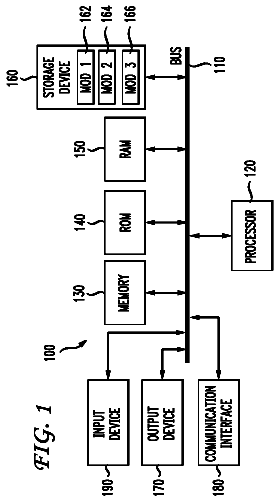
FIG. 1 is a block diagram of a computer system suitable for use with present invention;
FIG. 2 is a conceptual block diagram of the elements of the inventive system in a network environment;
FIG. 3 is a conceptual block diagram of the elements of an alternative implementation of the inventive system in a network environment;
FIGS. 4-5 illustrate conceptually the construction of the inventive database and the information contained therein;
FIG. 6A is a screen capture of the graphic user interface of the inventive server illustrating a selection of cards in accordance with the present invention;
FIG. 6B is a screen capture of the graphic user interface of the inventive server illustrating a the panels of a selected card in accordance with the present invention;
FIG. 6C is a screen capture of the graphic user interface of the inventive server illustrating a card template in accordance with the present invention;
FIG. 6D is a screen capture of the graphic user interface of the inventive server illustrating a customized card in accordance with the present invention;
FIG. 6E-K are screen captures of the graphic user interface of the inventive server illustrating various dialog screen through which a network user interacts with the system of the present invention;
FIG. 7 is a flow diagram illustrating the processes of customizing/creating a card in accordance with the present invention;
FIG. 8 is a conceptual block diagram illustrating the elements of the inventive vendor system in accordance with the present invention;
FIG. 9 is a conceptual illustration of the data structures used to represent a card in accordance with the present invention;
FIG. 10 illustrates conceptually the construction of the vendor database and the information contained therein;
FIGS. 11A-C are flow charts illustrating the processes performed by a client system to print a card in accordance with the present invention; and
FIG. 12A is a conceptual illustration of a card panel including a bar code and SKU and Lot data useful for matching the card with a gift and for printing shipping labels in accordance with the present invention;
FIG. 12B is a conceptual illustration of a card panel including a bar code and a destination address in accordance with the present invention;
FIG. 12C is a conceptual illustration of a card panel including a bar code and a pick list of one or more items to be shipped with the card of the present invention; and
FIG. 13 is a flow chart illustrating the processes for utilizing information on the printed card to bundle other items, for shipment as a single entity, in accordance with the present invention.
Detailed description
FIG. 1 illustrates the system architecture for a computer system 100 such as a Sun SparcStation 5 workstation, commercially available from Sun Microsystems of Palo Alto, Calif., or an IBM RS/6000 workstation, or IBM Aptiva PC, both commercially available from International Business Machines Corp. of Armonk, N.Y., on which the invention may be implemented. The exemplary computer system of FIG. 1 is for descriptive purposes only. Although the description may refer to terms commonly used in describing particular computer systems, the description and concepts equally apply to other systems, including systems having architectures dissimilar to FIG. 1.
Computer system 100 includes a central processing unit (CPU) 105, which may be implemented with a conventional microprocessor, a random access memory (RAM) 110 for temporary storage of information, and a read only memory (ROM) 115 for permanent storage of information. A memory controller 120 is provided for controlling RAM 110.
A bus 130 interconnects the components of computer system 100. A bus controller 125 is provided for controlling bus 130. An interrupt controller 135 is used for receiving and processing various interrupt signals from the system components.
Mass storage may be provided by diskette 142, CD ROM 147, or hard drive 152. Data and software may be exchanged with computer system 100 via removable media such as diskette 142 and CD ROM 147. Diskette 142 is insertable into diskette drive 141 which is, in turn, connected to bus 30 by a controller 140. Similarly, CD ROM 147 is insertable into CD ROM drive 146 which is, in turn, connected to bus 130 by controller 145. Hard disk 152 is part of a fixed disk drive 151 which is connected to bus 130 by controller 150.
User input to computer system 100 may be provided by a number of devices. For example, a keyboard 156 and mouse 157 are connected to bus 130 by controller 155. An audio transducer 196, which may act as both a microphone and a speaker, is connected to bus 130 by audio controller 197, as illustrated. It will be obvious to those reasonably skilled in the art that other input devices, such as a pen and/or tabloid may be connected to bus 130 and an appropriate controller and software, as required. DMA controller 160 is provided for performing direct memory access to RAM 110. A visual display is generated by video controller 165 which controls video display 170. Computer system 100 also includes a communications adapter 190 which allows the system to be interconnected to a local area network (LAN) or a wide area network (WAN), schematically illustrated by bus 191 and network 195.
Operation of computer system 100 is generally controlled and coordinated by operating system software, such as Windows 95 or Windows NT.RTM., commercially available from Microsoft Corp., Redmond, Wash. The operating system controls allocation of system resources and performs tasks such as processing scheduling, memory management, networking, and I/O services, among things. In particular, an operating system resident in system memory and running on CPU 105 coordinates the operation of the other elements of computer system 100. The present invention may be implemented with any number of commercially available operating systems including OS/2.RTM., UNIX.RTM., Linux and Solaris.RTM., among others.
One or more applications such as a web browser, for example, Netscape Navigator, version 2.0 and thereafter commercially available from Netscape Communications Corporation. and Internet Explorer, version 1.0 and thereafter, commercially available from Microsoft Corporation, Redmond, Wash., may execute under the control of the operating system.
Communication Environment
FIG. 2 illustrates a telecommunications environment in which the invention may be practiced, such environment being for exemplary purposes only and not to be considered limiting. Network 200 of FIG. 2 illustrates a hybrid telecommunication environment including packet-switched data networks, such as the Internet and private Intranets, as well as apparatus bridging between the two. Not every element illustrated in FIG. 2 or described herein is necessary for the implementation or the operation of the invention.
As illustrated in FIG. 2, a global packet-switched network topology, illustrated as the Internet 205, interconnects various other computers in the network environment to the inventive system 250 of the present invention over a network. As will be understood by those skilled in the art, the Internet is essentially a network of networks which collectively form a global wide area network enabling processes at different network addresses, and typically in geographically disparate locations, to establish communication connections and to transmit data in a variety of formats. In the illustrative embodiment, any number of different transport protocols may be utilized between and among the various processes connectable across the Internet and private Intranets, e.g. Local Area Networks.
As illustrated in FIG. 2, in addition to system 250, a plurality of other computer systems 210, 212, 220 A-B, 230, 240, 250, 260, 265, and 270 are coupled, directly or indirectly, to the Internet 205. Each of these computer systems may be implemented with a computer architecture similar or equivalent to that described with reference to FIG. 1 and capable of executing a computer operating system, such as Windows NT 4.0, available from Microsoft Corporation, Redmond, Wash. Such an operating system is a multi-tasking operating system capable of executing multiple simultaneous threads of execution. Other commercially available operating systems such as Unix, Linux, OS/2, and Solaris may also be utilized. Computer systems 210-270 may utilize any of a number of technologies known in the arts to connect to Internet 205. For example, computer system 220A, which represents a network user, may be connected to the Internet through a dial-up connection to an Internet Service Provider, not shown, such as America On-line or Compuserve. Computer system 220B, representing another network user, may alternatively be coupled to the Internet through a cable modern and broadband cable network infrastructure, also not shown. Vendor distribution computer system 210 and vendor web server system 212, may be connected to the Internet utilizing frame relay technology and a high bandwidth connection, such as T1, T2 or T3 line. Computer system 230, representing a credit processing server, and computer system 240, representing a card vendor distribution center computer(s), may be similarly connected to Internet 205 using any of the previously-described techniques or any other techniques known in the arts.
Card Vendor System
Referring to FIG. 2, a conceptual block diagram of the card vendor system 250 in accordance with the present invention is illustrated. The system 250 comprises a web server 260, a database server 270 and database 280, and email server 288 operatively coupled, in the illustrative embodiment, via a private network 292, e.g., a packet-switched network, such as a Local Area Network executing the TCP/IP protocol. Network 292 is a private network which may further be used to connect to printer 283 to the distribution computer system 243 and database 241. In the illustrative embodiment network 292 may comprise a 100 megabit Ethernet network. A private network 290 couples both web server 260 and email server 288 to firewall server 265. Firewall server 265 is, in turn, connected to Internet 205, via a T1 line, or other connection such as a frame relay connection,
In the illustrative embodiment of the present invention, email server 288 may be implemented as a server executing an application program in accordance with the Post Office Protocol version 3.0 (POP3), such server capable of receiving and sending electronic mail in a manner understood by those skilled in the arts.
In a similar manner, firewall application 265 may be implemented as a server or network appliance executing any of a number of commercially available network security applications which prevent unauthorized access to private networks in a manner understood by those skilled in the arts.
In the illustrative embodiment, web server 260 performs the functions of a traditional web server enabling access to one or more web pages by other processes connected to Internet 205. In addition, webserver 260 contains display control module 266 which utilizes data representing a card, as retrieved from database 280, and data representing modifications to the selected card, as received from a network user, to render the selected card and its modifications in a WYSIWYG format for viewing by the network user.
Server 260 may be implemented using a hardware platform similar to that illustrated with reference to FIG. 1. Executing under the control of an operating system are one or more applications necessary for web server 260 to perform its appropriate functions. Specifically, web server 260 presents web pages to the network user and controls the flow of information to/from database server 270. In the illustrative embodiment, the functions performed by web server 260 may be implemented either with object-oriented programming techniques using the appropriate class definitions and objects for values within the database, or, alternatively, using a non-object oriented language such as the C++ programming language.
Web server 260 retains in memory one or more "pages" which collectively may comprise a web site used to visually present the information on the pages. One or more of the pages accessible on web server 260 may contain address information in the form of a Hypertext Markup Language (HTML) tag which may be downloaded over the Internet 205 to a browser process executing on any of the other computer systems connected to the network. Such HTML tag may include the IP address or E-mail address associated with the web site.
Web server 260 functions to render pages to a network user connected to the web server 260 and to pass data received from a network user to database through the appropriate Application Program Interfaces (APIs). In the illustrative embodiment, the web server 260 may utilize a plurality of Visual Basic, Java script files and/or Java applets to create active web pages. Web server 260 may include a database interface (not shown) which functions as the interface between web server 260 and database server 270. Such database interface may be implemented via ODBC, Remote Procedure Call libraries or other similar technologies which enables the interface to make remotely access the database server 270 and to service calls received from database server 270.
The distribution computer system 240 and its accompanying database 239 may be connected to system 250 via direct network connection or other connections such dialup modem, DSL or frame relay. Computer system 240 may be coupled to one or more network printers 285 and 286 via a private network such as a LAN.
In an alternative embodiment to that illustrated in FIG. 2, email server 288 and web server 260 may be implemented with applications which execute on the same computer system, as illustrated in FIG. 3.
Data Base Architecture
In the illustrative embodiment, database server 270 and database 280 may comprise a hardware platform and an operating system capable of executing one of a number of commercially available database products. In the illustrative embodiment, hardware platform may be implemented with a computer system similar to that described with reference to FIG. 1. The operating system may be implemented with the Windows NT 4.0 product from Microsoft. The database product may be implemented with Microsoft SQL Server Version 7.0, also commercially available from Microsoft Corporation. The structure of information, including the data fields, records, tables which comprise database 280 are described hereinafter and may also be designed using Microsoft SQL Server Version 7.0.
Query engine (not shown) receives information from web server 260 in the form of a query and supplies the query to database 280. The structure and organization of records within database 280 is set forth in greater detail with reference to FIG. 4-5. Database server 270 and database 280 communicate using SQL standard database query language. The SQL standard is published by the American National Standards Institute (ANSI). The database query engine which is integrated into database server filters the queries received from web server 260, such filters useful in focusing or customizing the scope of a database query. The information retrieved from database 280 may be forwarded by database server 270 to web server 260 using any number of know techniques such as remote procedural call libraries, as that previously described.
FIGS. 4-5 illustrate conceptually the tables which comprise database 280. Each record, as shown, includes one or more fields and an associated field descriptor, as illustrated. Multiple records of the same type, in turn, collectively form a table within database 280. A field within a record may serve as an index into another record. To further a better understanding of the architecture of database 280, the major tables, as illustrated conceptually by single record and its corresponding fields, are described below in greater detail.
User Table 402 is used to maintain information about a network user who has visited system 250 via a connection to webserver 260. Each record of User Table 402 includes fields for a user identifier, postal address, network address, age, marital status, telephone number, etc. The corresponding field descriptions, e.g. integer, variable character, number, etc., are illustrated in FIG. 4.
Card Table 404 is used to maintain information about a specific card of the master card list. Each record of Card Table 404 includes fields for a card identifier, price, card catalog identifier, text description, width and height of the card, a charity identifier, etc. The corresponding field descriptions are illustrated in FIG. 4A. In the illustrative embodiment, the actual cards may be stored in any graphical format, for example, jpg, gif, tif or bmp. The cards may be stored as part of or separate from database 280, as well as in the database 242 of distribution system 240 and database 218 of distribution system 210, both connectable to system 250. In the illustrative embodiment, the term "card" or "greeting card" is not limited to traditional hard copy cards but also includes images of one or more sides or panels of a card as may be stored in various graphical data formats and resolutions, in addition to those described herein. Further, the term "card" or "greeting card" is not limited to traditional hard copy cards but also includes other related forms of correspondence including announcements, invitations, business cards, notices, and other business and personal forms of communication.
Card Detail Table 406 (CardDet) is used to maintain information about a specific card which has been ordered by a network user. Each record of Card Detail Table 406 includes fields for the ship date, ship month, status, etc. The corresponding field descriptions are illustrated in FIG. 4.
The Card Detail Detail Table 408 (CardDetDet) is used to maintain information about changes or customizations made to the card by the network user. Each record of the Card Detail Detail Table 408 includes fields defining fields the font, size, color, text, X-position, Y-position, style, file name for an attached file containing graphics, digital photos, scanned data, etc. The corresponding field descriptions are illustrated in FIG. 4.
Charity Table 410 is used to maintain information relating to a specific charity from which proceeds of the card sale may be donated, as explained in greater detail hereinafter. Each record of Charity Table 410 includes fields for a charity identifier, charity description, organizational name, mailing address, etc. The corresponding field descriptions are illustrated in FIG. 5.
The remaining tables of FIGS. 4-5 include records having the information fields and field descriptors, as illustrated and which are self-explanatory. For example, the Card Ship info record 412 includes information relevant to the address to which the card is to be shipped. The user gift record 414 includes information about a gift with which the card is associated. The client table 416, client location record 418, client category 420, client key word record 422, and client profile record 422 all maintain information about a client (vendor) from which a gift was purchased and to which the card may be shipped for coordination with the shipment of the gift to the specified recipient. The card gift record 426 and user transmit record 428 include information useful in coordinating the shipment and printing of a card with a specified gift purchased at or shipped from a client's facilities. The occasion record 420 and occasion category record 432 include information fields describing a particular person, date and address for which a card was or may be ordered, and the nature of the occasion, e.g., birthday, anniversary, graduation, etc., respectively. Such information is useful for administrative and tracking purposes as well as for implementation of a reminder service. The ASPOBJ table 436 and ASPMAS table 434 include information fields used to enable the inventive system to customize the web page appearances in order to make it appear like an eCommerce vendor's web site. The ship type record 438 includes information describing the manner in which a card and/or the accompanying gift are to be transported to the recipient. Record 442-454 include the information fields and field descriptors, as illustrated in FIG. 4B, useful in administering the inventive system. The records 402-460 of database 280 are related. In particular, a specific entry of one table may be used as an index into a record of another table, as illustrated in the listing below in which each entry has the form:
TABLE-US-00001 [Tablename.Fieldname] REFERENCES [Tablename.Fieldname] [Category.CatParentId] REFERENCES [Category.CatId] [ClientCat.CCatParentId] REFERENCES [ClientCat.CCatId] [Aspobj.AOAspId] REFERENCES [Aspmas.AspId] [CardKeyword.CKCatId] REFERENCES [Category.CatId] [Charity.CharityCountryId] REFERENCES [Country.CountryId] [Client.CltCCatId] REFERENCES [ClientCat.CCatId] [ClientKeyword.CKCCatId] REFERENCES [ClientCat.CCatId] [ClientMailInfo.CMIShipCountryId] REFERENCES [Country.CountryId] [FreightRates.FCountryId] REFERENCES [Country.CountryId] [FreightRates.FSTId] REFERENCES [ShipType.STId] [Users.UserCountry] REFERENCES [Country.CountryId] [Users.UserCCType] REFERENCES [CCType.CCType] [Card.CardCatId] REFERENCES [Category.CatId] [Card.CardCharityId] REFERENCES [Charity.CharityId] [ClientLoc.CLocCltId] REFERENCES [Client.CltId] [ClientLoc.CLocCountryId] REFERENCES [Country.CountryId] [CltProfile.CPAOAspId & CPAOId] REFERENCES [Aspobj.AOAspId.AOId] [CltProfile.CPCltId] REFERENCES [Client.CltId] [Invoice.InvUserId] REFERENCES [Users.UserId] [Invoice.InvCountryId] REFERENCES [Country.CountryId] [Occasion.OccShipCountryId] REFERENCES [Country.CountryId] [Occasion.OccOccCatId] REFERENCES [OccCategory.OccCatId] [Occasion.OccUserId] REFERENCES [Users.UserId] [UserTrans.UTUserID] REFERENCES [Users.UserId] [CardDet.CDUserId & CDTransId] REFERENCES [UserTrans.UTUserID & UTTransId] [CardDet.CDCardId] REFERENCES [Card.CardId] [CLocStats.CLSCltId & CLSLocId] REFERENCES [ClientLoc.CLocCltId & CLocId] [ClocStats.CLSStatsID] REFERENCES [Statistic.StatsId] [UserGift.UGCLocCltId & UGCLocId] REFERENCES [ClientLoc.CLocCltId & CLocId] [UserGift.UGUserId & UGTransId] REFERENCES [UserTrans.UTUserID & UTTransId] [CardDetDet.CDDSrno] REFERENCES [CardDet.CDSrno] [CardDetDet.CDDUserId] REFERENCES [Users.UserId] [CardGift.CGCDSrno] REFERENCES [CardDet.CDSrno] [CardGift.CGUGSrno] REFERENCES [UserGift.UGSrno] [CardShipInfo.CSICDSrno] REFERENCES [CardDet.CDSrno] [CardShipInfo.CSIShipCountryId] REFERENCES [Country.CountryId] [CardShipInfo.CSISTId] REFERENCES [ShipType.STId] [InvDetl.IDCDSrno] REFERENCES [CardDet.CDSrno] [InvDetl.IDlInvNo] REFERENCES [Invoice.Invno] Webserver Interface
Upon connection to webserver 260, either directly or through a hyperlink from the website of a vendor client, a network user is presented with a graphic user interface. The graphic user interface includes a number of web pages which are resident on web server 260 and through which the network user may navigate. The web pages include a number of menus and dialog boxes which allow the network user to interact with the web server 260, particularly with the selection of a card and entering of the necessary information for customization of the card and specifying a recipient address. Sample web pages are illustrated in FIG. 6A-K and include various highlight options and dialog boxes through which a network user may interact with webserver 260.
FIG. 6A is a screen capture of the graphic user interface of the inventive web server illustrating a selection of cards rendered in thumbnail size, in accordance with the present invention. In the illustrative embodiment, web pages rendered by webserver 260 appear to be an extension of the web site from which the network user was most recently connected, which as illustrated is 4YourSoul.com. In order to emulate the look and feel of a vendor's web page, the inventive system stores within a database 280, particularly tables 436 and 434, a client identifier and data identifying the appropriate backgrounds, color schemes, font sizes, font styles, font colors, logos, and other graphic or sonic elements etc. which emulate the look and feel of the client web site and give the network user the impression that he/she is still connected to the vendor's web site. To accomplish the above illusion, a client identifier may be passed along with the hyperlink to web server 260. Web server 260 then uses the identifier to retrieve the appropriate parameters from tables 436 and 434 and other, as necessary, for rendering the web pages and graphic user interface in a manner which is similar to those of the vendor from whom the network user recently purchased goods or services. If a network user connect directly to the inventive system, the graphic user interface of the inventive system may be used.
In the illustrative embodiment, card 600 along with the other selectable cards are stored in a number of different formats and sizes. For example, to facilitate selection and customization, cards may be stored in database 280 as files in a thumbnail, intermediate and editable size. FIG. 6A is illustrates a selection of cards rendered in thumbnail size. FIG. 6B illustrates a card 600 in the intermediate size, as would be viewed by a network user following selection of the card. FIG. 6C illustrates a card 600 in editable size, as would be viewed by a network user during customization of the card. In database 280, the card files comprise graphical data, for example in bit map, .tif, .jpeg or other format, and may be arranged categorically according to particularly themes or occasion, e.g. birthdays, anniversaries, weddings, etc.
A fourth version of each card, from which the card is actually printed, is stored in any of databases 241, 239 and 218 of FIGS. 2-3. In these databases, the cards may be stored as an encrypted blob, e.g. a binary data file, for security purposes. This format may be obtained by encrypting the graphic data file of the card, for example, a .jpeg file, into a blob using any number of known commercially available encryption tools.
FIG. 6B illustrates card 600 as would be viewed by a network user on a web page 600 following selection of the card. As shown, card 600 is displayed with three panels 600A-C similar to the manner in which a card is viewed in hard copy or tangible form. A fourth side, 600D, not shown, may contain copyright information, vendor tracking information and various logos and trademarks of companies, as well as, possibly, the recipient's information.
FIG. 6C illustrates card 600 as would be viewed by a network user in uncustomized form, in accordance with the present invention. Having selected a card, a network user utilizing a pointing device, such as a mouse or pen, designates the coordinates on the card at which text or graphics are to be placed, and, thereafter, enters the customizations to the card, for example by typing in the text to be added to the card at the designated location. In addition, the user selects the font type, font style, font color and font size of the text. In an alternative embodiment of the invention, the user is able to transmit scanned data representing hand written text or graphics to web server 260 and view the scanned data. Alternatively, the user may transmit a file containing photographic or other graphic data to be integrated into the card. FIG. 6D illustrates card 600 as would be viewed by a network user in customized form, in accordance with the present invention.
Control module 266 of web server 260 receives the coordinate information and other information describing the user's customizations, as recorded in customization table 408 and renders the card and the customizations in a What You See is What You Get (WYSIWYG) manner for viewing by the network user, as illustrated in FIG. 6D. In this manner, rather than just entering text into a dialog box for placement in a predetermined location, the user is free to place a customized message in any of text, cursive hand writing, graphics or photographs any where on panels 600A-C and view the card and customizations together in a manner which approximates signing a hard copy card. The WYSIWYG module which enables recording of a card with customizations from a network user is described in further detail herein. Control module 266 includes algorithms which detect the nature of the data transmitted by the network user and formats the data appropriately for presentation to the use. In the case of scanned data, control module 266 utilizes optical character recognition algorithms to separate and eliminate any background information from meaningful characters in the scanned data. In the case of photographic or graphic data files, control module 266 attempts to recognize the data format and render the data within the parameters of the designated panel including any required sizing or clipping of images to for the panel. FIGS. 6C-D illustrate a card 600 as displayed on web page, as seen by a network user in both stock, i.e., unmodified, and customized, i.e., modified form, respectively.
FIG. 6E-K illustrate other web pages, in accordance with the inventive system, as would be displayed to a system user who is utilizing the reminder service of the inventive system. The reminder service enables a network user to enter various information about upcoming events, including dates, descriptions and recipients. The reminder service notifies the network user via e-mail of an up coming event and enables the network user to select cards for the designated recipients using the system described here.
The construction of web pages containing the appropriate dialog boxes and pull down menus is within the scope of those reasonably skilled in the arts and will not be described in further detail hereinafter for the sake of brevity.
Method of Operation
The description continues in the full USPTO document.
 Lapsed, fee not paid8 drawings