Cross-reference to related applications
This application is based on and claims priority under 35 USC 119 from Japanese Patent Application No. 2011-032530 filed Feb. 17, 2011.
Background
(i) Technical Field
The present invention relates to an image forming apparatus and an image forming method.
(ii) Related Art
An electrophotographic process is widely used for copying machines, printers, and the like.
Summary
According to an aspect of the invention, there is provided an image forming apparatus including an image carrier, a charging unit that charges the surface of the image carrier, an electrostatic latent image forming unit that forms an electrostatic latent image by exposure of the charged surface of the image carrier, a development unit that houses an electrostatic latent image developer containing a toner containing toner particles and inorganic particles externally added thereto and that develops the electrostatic latent image formed on the image carrier with the electrostatic latent image developer to form a toner image, an intermediate transfer body to which the toner image formed on the surface of the image carrier is transferred and the surface of which contains a resin material and fluororesin particles, a first transfer unit that first transfers the toner image formed on the surface of the image carrier to the surface of the intermediate transfer body, and a second transfer unit that second transfers the toner image transferred to the surface of the intermediate transfer body to a recording medium, and a cleaning unit that cleans the surface of the intermediate transfer body after the toner image transferred to the surface of the intermediate transfer body is second transferred to the recording medium, the cleaning unit including a cleaning blade provided in contact with the surface of the intermediate transfer body.
Brief description of the drawings
Exemplary embodiments of the present invention will be described in detail based on the following figures, wherein:
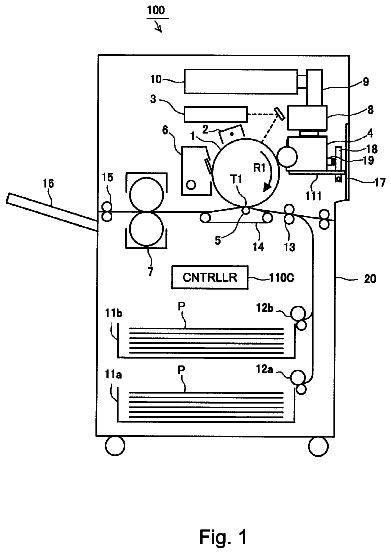
FIG. 1 is a schematic drawing showing a configuration of an image forming apparatus according to an exemplary embodiment of the present invention;
FIG. 2 is a schematic sectional view showing an intermediate transfer body of an image forming apparatus according to an exemplary embodiment of the present invention;
FIG. 3 is a schematic drawing showing a configuration of an intermediate transfer body cleaning device of an image forming apparatus according to an exemplary embodiment of the present invention;
FIGS. 4A to 4C are schematic drawings illustrating the function of an image forming apparatus according to an exemplary embodiment of the present invention; and
FIGS. 5A and 5B are schematic drawings illustrating a difference in the degree of elongation of fluorocarbon resin particles between a first cleaning blade and a second cleaning blade of an intermediate transfer body cleaning device in an image forming apparatus according to an exemplary embodiment of the present invention.
Detailed description
An exemplary embodiment of the present invention is described below.
FIG. 1 is a schematic drawing showing a configuration of an image forming apparatus according to an exemplary embodiment of the present invention.
As shown in FIG. 1, an image forming apparatus 101 according to an exemplary embodiment of the present invention includes an electrophotographic photoconductor 10 (an example of an image carrier) that is rotated in a clockwise direction, for example, as shown by arrow a, a charging device 20 (an example of a charging unit) that is provided above the electrophotographic photoconductor 10 so as to face the electrophotographic photoconductor 10 and charge the surface of the electrophotographic photoconductor 10, an exposure device 30 (an example of a latent image forming unit) that forms an electrostatic latent image by exposure of the surface of the electrophotographic photoconductor 10 charged by the charging device 20, a development device 40 (an example of a development unit) that forms a toner image on the surface of the electrophotographic photoconductor 10 by adhering a toner contained in a developer to the electrostatic latent image formed by the exposure device 30, a belt-shaped intermediate transfer body 50 that travels in a direction shown by arrow b while being in contact with the surface of the electrophotographic photoconductor 10 and to which the toner image formed on the surface of the electrophotographic photoconductor 10 is transferred, and a photoconductor cleaning device 70 (an example of a cleaning unit) that cleans the surface of the electrophotographic photoconductor 10.
The charging device 20, the exposure device 30, the development device 40, the intermediate transfer body 50, and the photoconductor cleaning device 70 are disposed around the circumference of the electrophotographic photoconductor 10, for example, in a clockwise direction.
The intermediate transfer body 50 is maintained by, for example, support rollers 50A and 50B, a back roller 50C, and a drive roller 50D while being imparted with tension from the inside. At the same time, the intermediate transfer body 50 is driven in the direction shown by arrow b with rotation of the drive roller 50D. In addition, a first transfer device 51 is provided at a position that faces the electrophotographic photoconductor 10 inside the intermediate transfer body 50 so that the intermediate transfer body 50 is charged to polarity different from the charge polarity of a toner and the toner on the electrophotographic photoconductor 10 is attracted to the surface (outer surface) of the intermediate transfer body 50. Further, a second transfer device 52 is provided below and outside the intermediate transfer body 50 to face the back roller 50C so that recording paper P (an example of a recording medium) is charged to polarity different from the charge polarity of the toner and the toner image formed on the intermediate transfer body 50 is transferred to the recording paper P.
Further, a recording paper feed device 53 that feeds the recording paper P to the second transfer device 52 and a fixing device 80 that fixes the toner image while transporting the recording paper P having the toner image formed thereon by the second transfer device 52 are provided below the intermediate transfer body 50.
The recording paper feed device 53 includes a pair of transport rollers 53A and a guide plate 53B that guides the recording paper P transported by the transport rollers 53A toward the second transfer device 52. On the other hand, the fixing device 80 includes a pair of fixing rollers 81 as heating rollers that fix the toner image by heating and pressing the recording paper P to which the toner image is transferred by the second transfer device 52, and a transport belt 82 that transports the recording paper P to the fixing rollers 81.
The recording paper P is transported in a direction shown by arrow c by the recording paper feed device 53, the second transfer device 52, and the fixing device 80.
Further, an intermediate transfer body cleaning device 54 that includes cleaning blades (a first cleaning blade 56 and a second cleaning blade 57) is provided on the intermediate transfer body 50 so that the toner remaining on the intermediate transfer body 50 after the toner image is transferred to the recording paper P by the second transfer device 52.
The principal component members of the image forming apparatus 101 according to an exemplary embodiment of the present invention are described in detail below.
--Developer--
The developer may be a one-component developer containing a toner alone or a two-component developer containing a toner and a carrier.
First, the toner is described.
The toner contains toner particles containing a binder resin and, if required, other additives such as a colorant, a release agent, etc., and an external additive.
As the external additive, inorganic particles are used.
The toner particles are described.
Examples of the binder resin includes, but are not particularly limited to, homopolymers and copolymers of styrenes (e.g., styrene, chlorostyrene, and the like), monoolefins (e.g., ethylene, propylene, butylene, isoprene, and the like), vinyl esters (e.g., vinyl acetate, vinyl propionate, vinyl benzoate, vinyl butyrate, and the like), .alpha.-methylene aliphatic monocarboxylic acid esters (e.g., methyl acrylate, ethyl acrylate, butyl acrylate, dodecyl acrylate, octyl acrylate, phenyl acrylate, methyl methacrylate, ethyl methacrylate, butyl methacrylate, dodecyl methacrylate, and the like), vinyl ethers (e.g., vinyl methyl ether, vinyl ethyl ether, vinyl butyl ether, and the like), vinyl ketones (e.g., vinyl methyl ketone, vinyl hexyl ketone, vinyl isopropenyl ketone, and the like), and the like; and polyester resins produced by copolymerization of dicarboxylic acids and diols.
Typical examples of the binder resin include polystyrene, styrene-alkyl acrylate copolymers, styrene-alkyl methacrylate copolymers, styrene-acrylonitrile copolymers, styrene-butadiene copolymers, styrene-maleic anhydride copolymers, polyethylene resins, polypropylene resins, polyester resins, and the like.
Other typical examples of the binder resin include polyurethane, epoxy resins, silicone resins, polyamide, modified rosin, paraffin wax, and the like.
Examples of the other additive include a colorant, a release agent, a magnetic material, a charge control agent, an inorganic powder, and the like.
Typical examples of the colorant include magnetic powders (e.g., magnetite, ferrite, and the like), carbon black, aniline blue, calcoil blue, chrome yellow, ultramarine blue, DuPont oil red, quinoline yellow, methylene blue chloride, phthalocyanine blue, malachite green oxalate, lamp black, rose bengal, C. I. Pigment Red 48:1, C. I. Pigment Red 122, C. I. Pigment Red 57:1, C. I. Pigment Yellow 97, C. I. Pigment Yellow 17, C. I. Pigment Blue 15:1, C. I. Pigment Blue 15:3, and the like.
Examples of the release agent include, but are not limited to, hydrocarbon wax; natural wax such as carnauba wax, rice wax, candelilla wax, and the like; synthetic or mineral-petroleum wax such as montan wax and the like; and ester wax such as fatty acid esters, montanoic acid esters, and the like.
The characteristics of the toner particles are described.
The toner particles preferably have an average shape factor (shape factor=number-average shape factor represented by (ML.sup.2/A).times.(.pi./4).times.100 wherein ML represents the maximum length of particles, and A represents the projected area of particles) of 100 or more and 150 or less. The average shape factor is more preferably 105 or more and 145 or less and still more preferably 110 or more and 140 or less.
The toner particles preferably have a volume-average particle diameter D50v of 2.0 .mu.m or more and 10 .mu.m or less, preferably 2.0 .mu.m or more and 6.5 .mu.m or less, more preferably 2.0 .mu.m or more and 5.5 .mu.m or less, and most preferably 2.0 .mu.m or more and 4.5 .mu.m or less. The lower limit of the volume-average particle diameter D50v is preferably 2.5 .mu.m or more and more preferably 3.0 .mu.m or more.
The method for measuring the volume-average particle diameter D50v of the toner particles is as follows.
First, 0.5 mg or more and 50 mg or less of a measurement sample is added to 2 ml of a 5 mass % aqueous solution of a surfactant (desirably, sodium alkylbenzene sulfonate) as a dispersant, and the resultant mixture is added to 100 ml or more and 150 ml or less of an electrolytic solution. The electrolytic solution in which the measurement sample is suspended is subjected to dispersion treatment for about 1 minute using an ultrasonic disperser. A particle size distribution of particles within the particle diameter range of 2.0 .mu.m or more and 60 .mu.m or less is measured with Coulter Multisizer II (manufactured by Beckmann-Coulter Inc.) using an aperture having a diameter of 100 .mu.m. The number of particles to be measured is about 50,000.
A volume accumulation distribution from the smaller particle size is plotted against the particle size ranges (channels) into which the measured particle size distribution is divided. The particle diameter corresponding to an accumulation of 50% is defined as the volume-average particle diameter D50v.
The external additive is described.
For example, inorganic particles are used as the external additive.
Examples of the inorganic particles used as the external additive include SiO.sub.2, TiO.sub.2, Al.sub.2O.sub.3, CuO, ZnO, SnO.sub.2, CeO.sub.2, Fe.sub.2O.sub.3, MgO, BaO, CaO, K.sub.2O, Na.sub.2O, ZrO.sub.2, CaO.SiO.sub.2, K.sub.2O.(TiO.sub.2).sub.n, Al.sub.2O.sub.3.2SiO.sub.2, CaCO.sub.3, MgCO.sub.3, BaSO.sub.4, MgSO.sub.4, and the like.
The volume-average particle diameter of the inorganic particles as the external additive is, for example, in the range of 7 nm or more and 60 nm or less, and preferably 10 nm or more and 50 nm or less.
The surfaces of the inorganic particles used as the external additive may be previously hydrophobized. The hydrophobic treatment is performed by, for example, immersing the inorganic particles in a hydrophobizing agent. Examples of the hydrophobizing agent include, but are not limited to, a silane coupling agent, silicone oil, a titanate coupling agent, an aluminum coupling agent, and the like. These may be used alone or in combination of two or more.
The amount of the inorganic particles externally added as the external additive is, for example, 0.5 parts by mass or more and 3.0 parts by mass or less, preferably 0.8 parts by mass or more and 2.5 parts by mass or less, relative to 100 parts by mass of the toner particles.
Lubricant particles (solid lubricant particles) may be also used as the external additive.
Examples of the lubricant particles used as the external additive include particles of fluorocarbon resins, polyolefins, fatty acid metal salts, and the like.
Examples of the fluorocarbon resins include polytetrafluoroethylene (PTFE), tetrafluoroethylene-perfluoroalkylvinyl ether copolymers (PFA), tetrafluoroethylene-hexafluoropropylene copolymers (FEP), polyvinylidene fluoride (PVDF), tetrafluoroethylene-ethylene copolymers (ETFE), polychlorotrifluoroethylene (PCTFE), chlorotrifluoroethylene-ethylene copolymers (ECTFE), polyvinyl fluoride (PVF), fluoroolefin-vinyl ether copolymers, vinylidene fluoride-tetrafluoroethylene copolymers, and vinylidene fluoride-hexafluoropropylene copolymers.
Examples of the polyolefins include waxes such as paraffin wax, paraffin latex, microcrystalline wax, and the like. In particular, polyethylene wax and polypropylene wax are used.
Examples of the fatty acid metal salts include salts of stearic acid with metals such as zinc, cadmium, barium, lead, iron, nickel, cobalt, copper, aluminum, magnesium, and the like; dibasic lead stearate; salts of oleic acid with metals such as zinc, magnesium, iron, cobalt, copper, lead, calcium, and the like; salts of palmitic acid with metals such as aluminum, calcium, and the like; lead caprylate; lead caproate; zinc linoleate; cobalt linoleate; calcium ricinoleate; salts of lichinoleic acid with metals such as zinc, cadmium, and the like; and mixtures thereof.
The volume-average particle diameter of the lubricant particles added as the external additive is, for example, 0.1 .mu.m or more and 10 .mu.m or less, preferably 0.3 .mu.m or more and 6 .mu.m or less, and more preferably 4 .mu.m or more and 6 .mu.m or less.
The amount of the lubricant particles externally added as the external additive is, for example, 0.1 parts by mass or more and 5 parts by mass or less and preferably 0.12 parts by mass or more and 0.5 parts by mass or less, based on 100 parts by mass of the toner particles.
If required, other external additives (for example, inorganic particles having a volume-average particle diameter of 80 nm or more and 400 nm or less) may be added.
The volume-average particle diameter of the external additive is measured with a laser diffraction particle size distribution analyzer (LA-700: manufactured by Horiba Ltd.).
Specifically, a dispersion solution of a sample is prepared so that the solid content is about 2 g, and ion exchange water is added to the dispersion solution until about 40 ml. The resultant solution is poured into a cell until a proper concentration is obtained, and then the concentration in the cell is stabilized by waiting for about 2 minutes, followed by measurement. The volume-average particle sizes of the channels are accumulated from the smaller volume-average particle size, and the particle size corresponding to an accumulation of 50% is defined as the volume-average particle diameter.
The method for producing the toner is described.
First, the toner particles are not particularly limited by the production method. For example, the toner particles are produced by a kneading-grinding method of kneading, grinding, and classifying a mixture of a binder resin, a colorant, and a release agent, and if required, a charge control agent; a method of changing the shape of particles, which are produced by the kneading-grinding method, by mechanical impact force or heat energy; an emulsion polymerization aggregation method of emulsion-polymerizing a polymerizable monomer of a binder resin, mixing the resultant dispersion solution with a dispersion solution containing a colorant and a release agent, and if required, a charge control agent, followed by aggregation and heat-fusion; a suspension polymerization method of suspending a solution of a polymerizable monomer for forming a binder resin, a colorant, and a release agent, and if required, a charge control agent in an aqueous solvent, followed by polymerization; or a dissolution suspension method of suspending a solution of a binder resin, a colorant, and a release agent, and if required, a charge control agent in an aqueous solvent, followed by granulation.
Further, a known method such as a production method of adhering aggregate particles to the toner particles, which are produced by the above-described method and used as cores, followed by heat-fusion to form a core-shell structure may be used. As the toner producing method, from the viewpoint of shape control and particle size distribution control, the suspension polymerization method, the emulsion polymerization aggregation method, and the dissolution suspension method are desired because of production using an aqueous solvent. Among these, the emulsion polymerization aggregation method is particularly desired.
In addition, the toner is produced by mixing the toner particles with the external additives using a Henschel mixer or a V blender. When the toner particles are produced by a wet method, the external additives may be added by a wet method.
Next, the carrier is described.
The carrier is not particularly limited, and a known carrier may be used. Examples of the carrier include a resin-coated carrier, a magnetic dispersion-type carrier, a resin dispersion-type carrier, and the like.
In addition, the mixing ratio (weight ratio) of the toner to the carrier (toner:carrier) in the two-component developer is, for example, preferably in the range of about 1:100 to 30:100, and more preferably in the range of about 3:100 to 20:100.
--Electrophotographic Photoconductor--
The electrophotographic photoconductor 10 is, for example, an inorganic photoconductor including a photosensitive layer that is provided on a conductive substrate and composed of an inorganic material, or an organic photoconductor including a photosensitive layer that is composed of an organic material. The organic photoconductor is, for example, a separated-function photoconductor including a charge generating layer that generates charges by conductive exposure and a charge transport layer that transports charges, both layers being laminated on a conductive substrate, or a photoconductor including a single photosensitive layer that functions to generate charges and transports charges and that is provided on the conductive substrate. The inorganic photoconductor is, for example, a photoconductor including a photosensitive layer that is provided on a conductive substrate and that is composed of amorphous silicon.
In addition, the shape of the electrophotographic photoconductor 10 is not limited to a cylindrical shape, and for example, a known shape such as a sheet shape, a plate shape, or the like may be used.
--Charging Device--
The charging device 20 is, for example, a contact charger using a conductive charging roller, a charging brush, a charging film, a charging rubber blade, or a charging tube. Also, the charging device 20 is, for example, a known charger such as a noncontact roller charger, a scorotron charger or a corotron charger using corona discharge. The contact charger is desired as the charging device 20.
A charger of a system in which a voltage generated by superimposing alternating current on direct current is applied easily produces a discharge product. However, in the exemplary embodiment, even when such a system is used, adhesion and deposition of the discharge product on the electrophotographic photoconductor 10 is suppressed, thereby suppressing uncopied spots on an image.
--Exposure Device--
As the exposure device 30, for example, an optical-system device may be used, in which the surface of the electrophotographic photoconductor 10 is exposed in an image form to light of a semiconductor laser, a LED, or a liquid crystal shutter. The wavelength of a light source falls in the spectral sensitivity region of the electrophotographic photoconductor 10. As the wavelength of the semiconductor laser, for example, a near-infrared region having an oscillation wavelength at about 780 nm may be used. However, the wavelength is not limited to this, and a laser having an oscillation wavelength of the order of 600 nm or a blue laser having an oscillation wavelength of 400 nm or more and 450 nm or less may be used. In addition, for example, a surface emitting laser light source of a type that emits multi-beams for forming a color image is effective as the exposure device 30.
--Development Device--
The development device 40 is, for example, disposed to face the electrophotographic photoconductor 10 within a development region, and includes, for example, a development container 41 (development device body) that contains the developer (two-component developer) containing the toner and the carrier, and a replenishing developer container (toner cartridge) 47. The development container 41 includes a development container body 41A and a development container cover 41B that closes the upper end of the development container body 41A.
The development container body 41A includes, for example, a development roll chamber 42A that contains a development roll (an example of a development support) 42 therein, and a first stirring chamber 43A and a second stirring chamber 44A adjacent to the first stirring chamber 43A, both stirring chambers 43A and 43B being adjacent to the development roll chamber 42A. In addition, a layer thickness regulating member 45 is provided in the development roll chamber 42A in order to regulate the thickness of a developer layer on the surface of the development roll 42, for example, when the development container cover 41B is attached to the development container body 41A.
The first stirring chamber 43A and the second stirring chamber 44A are partitioned by, for example, a partition wall 41C. Although not shown in the drawing, the first stirring chamber 43A and the second stirring chamber 44A are communicated with each other through openings provided at both ends of the partition wall 41C in the longitudinal direction (longitudinal direction of the development device), forming a circulation stirring chamber (43A+44A) by the first stirring chamber 43A and the second stirring chamber 44A.
The development roll 42 is disposed in the development roll chamber 42A so as to face the electrophotographic photoconductor 10. Although not shown in the drawing, the development roll 42 includes a magnetic roll (fixed magnet) having magnetism and a sleeve provided on the outside of the magnetic roll. In the first stirring chamber 43A, the developer is attracted to the surface of the development roll 42 by virtue of the magnetic force of the magnetic roll and transported to the development region. The roll axis of the development roll 42 is rotatably supported by the development container body 41A. In this case, the development roll 42 and the electrophotographic photoconductor 10 are rotated in the same direction so that in the opposing portion therebetween, the developer attracted to the surface of the development roll 42 is transported to the development region in the direction opposite to the moving direction of the electrophotographic photoconductor 10.
In addition, a bias power supply (not shown) is connected to the sleeve of the development roll 42 so as to apply a development bias. In this exemplary embodiment, a bias generated by superimposing an alternating-current component (AC) on a direct-current component (DC) is applied so that an alternating electric field is applied to the development region.
In addition, a first stirring member 43 (stirring and transport member) and a second stirring member 44 (stirring and transport member) are disposed in the first stirring chamber 43A and the second stirring chamber 44A, respectively, so that the developer is transported under stirring. The first stirring member 43 includes a first rotational shaft extending in the axial direction of the development roll 42 and a stirring and transport blade (projecting portion) helically fixed to the periphery of the rotational shaft. Similarly, the second stirring member 44 includes a second rotational shaft and a stirring and transport blade (projecting portion). The stirring members are rotatably supported by the development container body 41A. The first stirring member 43 and the second stirring member 44 are disposed so that the developers in the first stirring chamber 43A and in the second stirring chamber 44A are transferred in opposite directions by the rotations thereof.
In addition, an end of a replenishing transport path 46 is connected to one of the ends of the second stirring chamber 44A in the longitudinal direction in order to supply the replenishing developer, that contains a replenishing toner and a replenishing carrier, to the second stirring chamber 44A. Further, a replenishing developer container 47 that contains the replenishing developer is connected to the other end of the replenishing transport path 46.
The replenishing developer is supplied from the replenishing developer container (toner cartridge) 47 to the development device 40 (second stirring chamber 44A) through the replenishing transport path 46.
--Transfer Device--
The first transfer device 51 and the second transfer device 52 are each, for example, a contact transfer charger using a belt, a roller, a film, or a rubber blade, or a known transfer charger such as a scorotron transfer charger or a corotron transfer charger using corona discharge.
--Intermediate Transfer Body--
As shown in FIG. 2, the intermediate transfer body 50 includes, for example, an endless belt composed of a laminate of a base layer 91 having a thickness of 30 .mu.m or more and 80 .mu.m or less and the outermost layer 92 provided on the periphery of the base layer 91 and having a thickness of 5 .mu.m or more and 70 .mu.m or less.
As the outermost layer 92, a layer containing a resin material and fluorocarbon resin particles is used. Therefore, the surface (outer surface) of the intermediate transfer body 50 contains the resin material and the fluorocarbon resin particles.
In FIG. 2, reference numeral 93 denotes the fluorocarbon resin particles.
The constituent materials and characteristics of the intermediate transfer body 50 are described below.
First, the outermost layer 92 is described.
The outermost layer 92 contains the resin material, the fluorocarbon resin particles, and if required, other additives such as a conductive agent, etc.
The resin material preferably has a Young's modulus of 3500 MPa or more and more preferably 4000 MPa or more depending on the belt thickness, because the mechanical properties as a belt are satisfied. The resin material is not limited as long as it satisfies the Young's modulus. Examples thereof include polyimide resins, polyamide resins, polyamide-imide resins, polyether-ether-ester resins, polyarylate resins, polyester resins, and polyester resins containing a reinforcing material.
The Young's modulus is determined from a gradient of a tangent drawn to a curve within an initial strain region of a stress-strain curve obtained by a tensile test according to JIS K7127 (1999). The measurement is performed using a strip specimen (width 6 mm, length 130 mm) and dumbbell No. 1 under the conditions including a test speed of 500 mm/min and a thickness set to the thickness of the belt body.
Among these resin materials, the polyimide resins are desired. The polyimide resins are materials with high Young's modulus and thus produce less deformation than the other resins during driving (stress of the support roll, the cleaning blade, and the like), thereby forming the intermediate transfer body (belt) causing little image defects such as color shift.
Examples of the polyimide resins include imidized products of polyamic acids that are each a polymer of tetracarboxylic dianhydride and diamine compound. Specifically, the polyimide resins are produced by, for example, imidizing polyamic acids that are each prepared as a polyamic acid solution by polymerization reaction of equimolar amounts of a tetracarboxylic dianhydride and a diamine compound in a solvent.
Examples of the tetracarboxylic dianhydride include those represented by the following general formula (I).
##str00001##
In the general formula (I), R is a tetravalent organic group such as an aromatic group, an aliphatic group, an alicyclic group, a combination of aromatic and aliphatic groups, or such a group having a substituent.
Specific examples of the tetracarboxylic dianhydride include pyromellitic dianhydride, 3,3',4,4'-benzophenonetetracarboxylic dianhydride, 3,3',4,4'-biphenyltetracarboxylic dianhydride, 2,3,3',4-biphenyltetracarboxylic dianhydride, 2,3,6,7-naphthalenetetracarboxylic dianhydride, 1,2,5,6-naphthalenetetracarboxylic dianhydride, 1,4,5,8-naphthalenetetracarboxylic dianhydride, 2,2'-bis(3,4-dicarboxyphenyl)sulfonic dianhydride, perylene-3,4,9,10-tetracarboxylic dianhydride, bis(3,4-dicarboxyphenyl)ether dianhydride, ethylenetetracarboxylic dianhydride, and the like.
Specific examples of the diamine compound include 4,4'-diaminodiphenyl ether, 4,4'-diaminodiphenyl methane, 3,3'-diaminodiphenyl methane, 3,3'-dichlorobenzidine, 4,4'-diaminodiphenyl sulfide, 3,3'-diaminodiphenyl sulfone, 1,5-diaminonaphthalene, m-phenylenediamine, p-phenylenediamine, 3,3'-dimethyl-4,4'-biphenyldiamine, benzidine, 3,3'-dimethylbenzidine, 3,3'-dimethoxybenzidine, 4,4'-diaminodiphenylsulfone, 4,4'-diaminodiphenylpropane, 2,4-bis(.beta.-amino-tert-butyl)toluene, bis(p-.beta.-amino-tert-butylphenyl)ether, bis(p-.beta.-methyl-.delta.-aminophenyl)benzene, bis-p-(1,1-dimethyl-5-amino-bentyl)benzene, 1-isopropyl-2,4-m-phenylenediamine, m-xylylenediamine, p-xylylenediamine, di(p-aminocyclohexyl)methane, hexamethylenediamine, heptamethylenediamine, octamethylenediamine, nonamethylenediamine, decamethylenediamine, diaminopropyltetramethylene, 3-methylheptamethylenediamine, 4,4-dimethylheptamethylenediamine, 2,11-diaminododecane, 1,2-bis-3-aminopropoxyethane, 2,2-dimethylpropylenediamine, 3-methoxyhexamethylenediamine, 2,5-dimethylheptamethylenediamine, 3-methylheptamethylenediamine, 5-methylnonamethylenediamine, 2,17-diaminoeicosadecane, 1,4-diaminocyclohexane, 1,10-diamino-1,10-dimethyldecane, 12-diaminooctadecane, 2,2-bis[4-(4-aminophenoxy)phenyl]propane, piperazine, H.sub.2N(CH.sub.2).sub.3O(CH.sub.2).sub.2O(CH.sub.2)NH.sub.2, H.sub.2N(CH.sub.2).sub.3S(CH.sub.2).sub.3NH.sub.2, H.sub.2N(CH.sub.2).sub.3N(CH.sub.3).sub.2(CH.sub.2).sub.3NH.sub.2, and the like.
In the polymerization reaction of the tetracarboxylic dianhydride and the diamine, a polar solvent (organic polar solvent) is preferably used as a solvent from the viewpoint of solubility, etc. As the polar solvent, N,N-dialkylamides may be used. Specific examples thereof include N,N-dialkylamides having a low molecular weight, such as N,N-dimethylformamide, N,N-dimethylacetamide, N,N-diethylformamide, N,N-diethylacetamide, N,N-dimethylmethoxyacetamide, dimethylsulfoxide, hexamethylphosphortriamide, N-methyl-2-pyrrolidone, pyridine, tetramethylenesulfone, dimethyltetramethylene sulfone, and the like. These may be used alone or in combination of two or more.
The content of the polyimide resin is, for example, 10% by mass or more and 80% by mass or less, preferably 20% by mass or more and 75% by mass or less, and more preferably 40% by mass or more and 70% by mass or less based on the total of the constituents of the layer.
These polyimide resins may be used alone or in combination of two or more.
Besides the polyimide resin, another resin material may be combined within a range where retention of releasability is not impaired. Examples of the other resin include polyamide resins, polyamide-imide resins, polyether-ether-ester resins, polyarylate resins, polyester resins, polyester resins containing a reinforcing material, and the like.
The fluorocarbon resin particles are described.
Examples of the fluorocarbon resin particles include particles of tetrafluoroethylene resins, chlorotrifluoroethylene resins, hexafluoropropylene resins, vinyl fluoride resins, vinylidene fluoride resins, dichlorodifluoroethylene resins, and copolymers thereof.
Among these resins, polytetrafluoroethylene (tetrafluoroethylene resins "PTFE"), a tetrafluoroethylene-hexafluoropropylene-perfluoroalkylvinyl ether copolymer (FEP), and a tetrafluoroethylene-perfluoroalkylvinyl ether copolymer (PFA) are desired for the fluorocarbon resin particles.
The fluorocarbon resin particles are contained as initial particles, secondary particles having a secondary particle diameter (preferably 1 .mu.m or less and more preferably 0.5 .mu.m or less), or a mixture thereof.
This represents that the fluorocarbon resin particles are contained and dispersed as initial particles, secondary particles (aggregates of at least two initial particles), or a mixture thereof, and that the secondary particle diameter of at least aggregate particles is in the above-described range, i.e., the fluorocarbon resin particles are dispersed with suppressed aggregation.
The initial particle diameter (particle diameter without aggregation) of the fluorocarbon resin particles is 0.1 .mu.m or more and 0.3 .mu.m or less.
Each of the initial particle diameter and the secondary particle diameter of the fluorocarbon resin particles is determined by preparing a specimen from the outermost layer, observing the specimen with SEM (scanning electron microscope) at, for example, a magnification of .times.5000 to measure the maximum diameter of each of the fluorocarbon resin particles in the state of initial particles or aggregate particles, and averaging the maximum diameters of 50 particles. In addition, a secondary electron image is observed with SEM (JSM-6700F manufactured by JEOL, Ltd.) at an acceleration voltage of 5 kV.
The content of the fluorocarbon resin particles is, for example, 1% by mass or more and 50% by mass or less, preferably 2% by mass or more and 45% by mass or less, and more preferably 3% by mass or more and 40% by mass or less based on the total of the constituents of the layer.
The type of the fluorocarbon resin particles may be one or combination of two or more types.
In order that the fluorocarbon resin particles are dispersed (contained) as described above, for example, a fluorinated graft polymer may be used as a dispersant.
As the fluorinated graft polymer, a copolymer of a macromonomer having a polymerizable functional group at one of the ends of its molecular chain and a polymerizable fluorinated monomer having an alkyl fluoride group may be used.
Specific examples of the fluorinated graft polymer include graft copolymers each composed of a macromonomer, such as a polymer or copolymer of an acrylate, a methacrylate, a styrene compound, or the like, and a fluorinated monomer such as perfluoroalkylethyl methacrylate, perfluoroalkyl methacrylate, or the like.
The polymerization ratio of the macromonomer and the polymerizable fluorinated monomer is, for example, 10% by mass or more and 50% by mass or less, preferably 10% by mass or more and 40% by mass or less, and more preferably 10% by mass or more and 30% by mass or less, in terms of the fluorine content in the fluorinated graft polymer.
The molecular weight of the fluorinated graft polymer is, for example, 5,000 or more and 20,000 or less, preferably 5,000 or more 17,500 or less, and more preferably 5,000 or more and 12,000 or less, in terms of number-average molecular weight.
The amount of the fluorinated graft polymer is, for example, 0.1% by mass or more and 10% by mass or less based on the fluorocarbon resin particles.
The conductive agent is described.
As the conductive agent, a conductive (for example, a volume resistivity of 10.sup.7 .OMEGA.cm, this applies to the description below) or semiconductive (for example, a volume resistivity of less than 10.sup.7 .OMEGA.cm or more and 10.sup.13 .OMEGA.cm or less, this applies to the description below) powder (including particles having an initial particle diameter of less than 10 .mu.m, preferably 1 .mu.m or less) may be used.
Examples of the conductive agent include, but are not particularly limited to, carbon black (e.g., Ketjenblack, acetylene black, carbon black with oxidized surfaces, and the like), metals (e.g., aluminum, nickel, and the like), metal oxide compounds (e.g., yttrium oxide, tin oxide, and the like), ionic conductive materials (e.g., potassium titanate, LiCl, and the like), conductive polymers (e.g., polyaniline, polypyrrole, polysulfone, polyacetylene, and the like).
The conductive agent is selected according to the purpose of use, but is preferably oxidized carbon black of pH 5 or less (preferably pH 4.5 or less and more preferably pH 4.0 or less), for example, carbon black with surfaces imparted with carboxyl groups, quinone groups, lactone groups, or hydroxyl groups, from the viewpoint of stability of electric resistance with time, and electric field dependence of suppressing electric field concentration due to a transfer voltage. In addition, from the viewpoint of imparting electric durability, the conductive agent is preferably a conductive polymer (for example, polyaniline).
The content of the conductive agent is, for example, 1% by mass or more and 50% by mass or less, preferably 2% by mass or more and 40% by mass or less, and more preferably 4% by mass or more and 30% by mass or less based on the total of the constituents of the layer.
These conductive agents may be used alone or in combination of two or more.
Next, the base layer 91 is described.
The base layer 91 includes a resin material. If required, the base layer 91 also includes a conductive agent.
The resin material is described.
The resin material preferably has a Young's modulus of 3500 MPa or more and more preferably 4000 MPa or more depending on the belt thickness because the mechanical properties as a belt are satisfied. The resin material is not limited as long as it satisfies the Young's modulus. Examples thereof include polyimide resins, polyamide resins, polyamide-imide resins, polyether-ether-ester resins, polyarylate resins, polyester resins, and polyester resins containing a reinforcing material.
The description continues in the full USPTO document.
 Lapsed, fee not paid7 drawings