Lapsed, fee not paid2 drawings
Firearms & Defense · US 8,607,494 B2
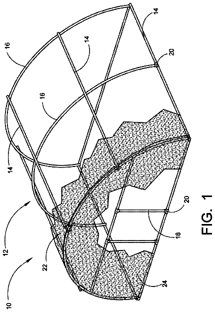
Firearm pull-through cleaning tool with integrated foldable handle
A novel firearm pull-through cleaning tool with an integrated foldable handle.
US 8,610,622 B2 · Assignee: Flex Force Enterprises LLC · Inventors: Sullivan; Jacob Ryan et al.
Sheet 1 of 3 from the published document. All sheets in the USPTO PDF
Claude doesn't help design weapons, ammunition or explosives, so this page has no Reinvent kit. To develop this one, work with a federally licensed manufacturer (many of these items are regulated) and a registered patent attorney or agent, listed on the USPTO roster.
An aimed or aiming firearm can be detected before it is able to shoot. Wideband radar signals can be used to identify the barrel of a firearm when the radar antenna and barrel are aiming at or near each other. Signal processing correlates reflected signals to the characteristics of specific firearms of interest, and alerts the user when someone is pointing such a firearm at them. Modern wideband radar systems with fast signal processing speed can enable real-time detection of firearm threats in crowded and cluttered areas before they shoot, which has never before been possible. Related systems, apparatus, methods, and articles are also described.
Since the advent of warfare, military leaders have understood the advantage of surprise and confusion. This is clearly evident by the effectiveness and use of snipers, ambushes, sneak attacks, and guerrilla tactics. In addition, military leaders have understood the importance of situational awareness during active combat operation as indicated by the time and resources devoted to combat communication (from the use of flags and trumpets to modern radios) and troop concealment (from the use of smoke, terrain, and camouflage). The detection, classification, and location of threats is critical to the success of any military operation. Before the advent of modern warfare, military leaders had little access to real-time situational awareness and tactical threat detection beyond the use of scouts and telescopes, and the individual warfighter had no access at all. With the advent of modern warfa
All 3 drawing sheets from the published document, cropped to the drawing.
What the patent claimed, word for word. All of it is now free to use.
The subject matter described herein relates to methods and sensor systems, including but not necessarily limited to the use of wideband radar systems to detect enemies aiming weapon barrels, including those of cannons or firearms (such as for example rifles, machine guns, or pistols), at or near the user.
Since the advent of warfare, military leaders have understood the advantage of surprise and confusion. This is clearly evident by the effectiveness and use of snipers, ambushes, sneak attacks, and guerrilla tactics. In addition, military leaders have understood the importance of situational awareness during active combat operation as indicated by the time and resources devoted to combat communication (from the use of flags and trumpets to modern radios) and troop concealment (from the use of smoke, terrain, and camouflage).
The detection, classification, and location of threats is critical to the success of any military operation. Before the advent of modern warfare, military leaders had little access to real-time situational awareness and tactical threat detection beyond the use of scouts and telescopes, and the individual warfighter had no access at all. With the advent of modern warfare came the application of technology to increase situational awareness both before combat (to reduce the effectiveness of enemy snipers, ambushes, and sneak attacks), and during combat (to increase the individual warfighters survivability and effectiveness).
The rapid increase of military technology has brought about the possibility of real-time tactical threat detection and location at the squad level. Examples of some of these emerging technologies include acoustic and infrared shot detection. These electro-optical and acoustic systems have been developed to help triangulate the location of a sniper once they fire. Project Overwatch uses thermal imagers, and new system products, such as Boomerang, use acoustic echolocation to identify the direction and distance of snipers once they fire. These systems greatly improve the speed and effectiveness of sniper response, as friendly forces can protect themselves from the direction of the shooter, and can more quickly identify the shooter location and mount a counterattack. From a counter-sniper perspective, these systems provide significant advantages. Unfortunately, the initial damage done by the shooter is unaffected. The officer, specialist, or materiel still will already have been fired upon by the time these systems are able to assist the tactical warfighter.
Despite the wide-ranging efforts by numerous researchers and product developers including those above, none of the conventional solutions is optimal for identifying and locating enemy combatants in crowded, short-range environments before they are able to attack, nor can they provide precise location in longer-range scenarios after an attack. Detection sensor technologies help identify the presence of people and weapons, but have difficulty detecting intent to harm. Reaction sensor technologies help identify the location and direction from which an attack was launched, but they provide little value or comfort to the victim, nor do they provide sufficient precision to direct other sensor and weapon resources against the attacker. Instead, what forces facing insurgents, snipers, and terrorists desperately need is a sensor technology that can detect the presence and location of a shooter that is poised to strike, and the precise location of a shooter immediately after an attack. This sensor system must then alert the user in a timely manner so that defensive measures can be undertaken and plans for counterattack initiated immediately.
In one aspect, a method of weapon threat detection includes transmitting radar signals towards a potential threat, receiving reflected radar signals that have been reflected from the potential threat, and employing signal processing to determine if a weapon barrel is pointed at or near a target of interest by a potential or continuing threat. If so, the weapon barrel is considered to be a weapon threat and an alert is provided.
In an interrelated aspect, a weapon threat detection system includes an outbound antenna apparatus that transmits an outbound radio frequency signal toward a potential threat and an inbound antenna that receives an inbound reflected radio frequency signal from the potential or continuing threat. A processor analyzes the inbound reflected radar signals to determine whether the threat includes a weapon barrel pointed in the direction of the receiving antenna apparatus.
In a further interrelated aspect, radio frequency signals are transmitted towards a zone of interest containing a plurality of firearms from a first location and radio frequency signals reflected from the zone of interest are received. The received radio frequency signals are compared to a library of radio frequency signatures and/or patterns for a plurality of different firearms to identify firearms in the zone of interest. It is then determined using the received radio frequency signals whether the identified firearms in the zone of interest are aimed at the first location or whether they are aimed at a different location. Data characterizing at least one firearm in the zone of interest can then be provided.
In some variations one or more of the following can optionally be included. The processed signal can optionally be compared to a library of one or more pre-characterized weapon threats to identify whether or not a weapon threat is detected. The transmission of the transmitted radar signals can optionally be made with high directionality greater than about 10. The transmitted radar signals can optionally cover a range of frequencies that can be propagated down one or more firearm barrels. The received radar signals can optionally have variances in phase and amplitude with both time and frequency due to the reflections associated with the specific waveguide characteristics of a set of weapon barrels. The set of weapon barrels of interest can optionally include one or more barrels of "small arms" firearms, such as for example shotguns, pistols, machine guns, other "infantry" weapons, 5.56 mm rifles, 7.62 mm rifles, and .50 caliber rifles. The alert signal can optionally include information that describes the direction of one or more weapon barrels detected. The alert signal can optionally include information that describes the range of one or more weapon barrels detected. The signal processing can optionally additionally resolve and identify reflections associated with the specific lengthwise radiating antenna characteristics of a set of weapon barrels and other firearm physical characteristics. The antenna used for transmitting and/or receiving the radar signals can optionally have a directivity characteristic between 100 and 100,000.
Articles are also described that comprise a tangibly embodied machine-readable medium operable to cause one or more machines (e.g., computers, etc.) to result in operations described herein. Similarly, computer systems are also described that may include a processor and a memory coupled to the processor. The memory may include one or more programs that cause the processor to perform one or more of the operations described herein.
The subject matter described herein can provide, among other possible advantages and beneficial features, systems, methods, techniques, apparatuses, and article of manufacture for detecting a threatening firearm that is aimed at or near a radar system configured to resolve the specific characteristics of that firearm. Implementations of this subject matter could provide critical advance warning of sniper attacks on tactical warfighters and supply convoys before they occur, which would save lives and materiel. Received radar signatures can be compared against specific waveguide and antenna characteristics of firearms and firearm barrels commonly employed by snipers that may be in the area. Unlike conventional imaging methods providing potential weapon detection benefits, the present subject matter can in some implementations be used in a manner in which alerts are provided only when such weapons are aimed at or near the radar antenna. This can eliminate many of the potential false positives of detecting weapons in areas that contain a large number of armed non-combatants or friendly forces. This feature can be quite valuable in providing heightened effectiveness and resource allocation efficiency, as well as for reduced casualty rates among non-combatants and friendly forces.
The details of one or more variations of the subject matter described herein are set forth in the accompanying drawings and the description below. Other features and advantages of the subject matter described herein will be apparent from the description and drawings, and from the claims.
The accompanying drawings, which are incorporated in and constitute a part of this specification, show certain aspects of the subject matter disclosed herein and, together with the description, help explain some of the principles associated with the disclosed embodiments. In the drawings,
FIG. 1 is a schematic illustration of a radar antenna directed at four different types of typical targets in a cluttered radio environment;
FIG. 2A is a schematic illustration of a radar antenna transmitting a signal towards the open mouth of a firearm barrel treated as a short-circuited circular waveguide;
FIG. 2B is a schematic illustration of a radar antenna waiting as a signal propagates down the firearm barrel and is reflected at the short circuit;
FIG. 2C is a schematic illustration of a radar antenna receiving a signal that has been reflected from the waveguide interior of a firearm barrel;
FIG. 3 is a schematic illustration of a radar antenna transmitting multiple frequency signals into the waveguide interiors of a firearm barrels in both resonant and anti-resonant characteristics;
FIG. 4 is a schematic illustration of a radar antenna receiving signals reflected back from a clutter object and from the waveguide interior of a firearm barrel;
FIG. 5 is an illustration of the voltage level on the inside surface of the waveguide interior of a firearm barrel while a signal is simultaneously transmitted into the mouth of, propagated within, and reflected from the closed portion of said barrel;
FIG. 6 is an illustration of the resonant and anti-resonant frequencies with wave propagation characteristics supported by the waveguide interior of a firearm barrel;
FIG. 7 is a schematic illustration of a radar antenna transmitting and receiving signals associated with the firearm barrel waveguide characteristics as well as the external firearm antenna radiation characteristics; and
FIG. 8 is a plan-view schematic illustration of an antenna with high directivity, which is then arrayed in a configuration to sense in many directions
The subject matter described herein can provide new sensing techniques and systems for improved threat detection and force protection. Counter-sniper and counter insurgency missions and operations of all types can be improved by employing the subject matter. Additional benefit can be gained by combining with other passive and active sensor technologies, and deploying trained counter-insurgency personnel in areas of heightened risk.
Existing limitations of conventional methods can be overcome by identifying threatening firearms and other weapons with barrels as they are aiming. Conventional personnel detection and weapon detection imaging systems help identify the presence of individuals and weapons, but they do little to predict intent or usage. Conventional post-shot location sensor systems do not protect the first target of a concealed attacker, nor do they give predictive warning of any kind. The methods provided herein accomplish both location and intent before the first shot is fired, giving tactical warfighters and operations personnel a critical advantage when facing enemy snipers, insurgents, or ambushes. Even when used in conjunction with post-shot systems, the methods provided herein provide greatly improved precision of location and identification of enemy combatants aiming weapons at or near its antenna.
According to various implementations of the currently disclosed subject matter, a wideband radar system can be used to detect weapon barrels while they are aiming at or near its antenna. Although there are a number of different weapon types that have barrels (including but not limited to cannons, firearms, mortars, and rocket tubes), these are hereafter defined by the general term firearms in the context of the present subject matter. These weapons, insofar as they are aimed at or near the radar system antenna, are herein referred to as firearm threats. Furthermore, in this subject matter, a weapon barrel is defined as the entire projective cavity for a given weapon, which may include the physical weapon barrel itself, as well as the chamber, and a round or other ammunition which may or may not be chambered or otherwise ready for firing.
Firearm threats are distinguished from detectable weapons that are not aimed at or near the radar system antenna, which are referred to herein as non-threatening firearms. As a practical matter, such weapons may not technically be firearms by other industry-recognized definitions. Also as a practical matter, those weapons may actually represent a near and immediate threat to the radar system user, other friendly forces, or materiel of value, either by aiming in a non-detectable manner, or by being configured in a manner that prevents or complicates detection. The following description first discusses the functional means by which a firearm threat can be detected by employing radar systems, then continues with details of a specific implementation of this subject matter.
A firearm threat detection method can in some implementations identify and locate an immediately threatening firearm, with the goal of increasing the safety and security of allied personnel and materiel in regions of conflict. There are a number of general concepts in conventional threat detection sensors, whereby a sensor could aid in the detection, location, and alerting of the user to the presence of concealed enemy personnel, firearms, or the direction and range of an attacker once a shot is fired.
Enemy personnel detection systems and methods have been highly sought after for decades due to the military effectiveness of sniper attacks and ambushes. Systems identifying the existence and location of persons are commercially available and can be effective even when a target is ostensibly hidden in foliage, buildings, ruins, or darkness. Personnel location sensors do not differentiate, however, between threatening and non-threatening personnel in an effective manner, so this technique is of limited value in an inhabited region where there are many non-combatants but few enemies.
One type of firearm detection method is to use an imaging system to detect radar signatures to identify and locate firearms that may be potential threats. Such a system detects the presence of specific types of weapons in the region, in some up-and-coming technologies behind foliage, doors, and other physical and/or visual obstructions. These methods and systems, once mature, may someday aid greatly in the identification and location of firearms, although they cannot provide feedback regarding the intent of the firearm owner. These sensors do not determine whether or not the firearm is present as an immediate threat to friendly forces. This is a significant problem in many developing countries, which can have high rates of civilian ownership of weapons that are similar to those used by enemy combatants.
Conventional firearm threat detection methods generally are capable of responding to a shot being fired. These methods use thermal, optical, or sonic sensors to identify the presence of a shot, locate the origin of the shot, and then alert and inform the user. Systems employing these methods can be accurate in their analysis of incoming attacks, and expedite response time, but they do not provide any warning of the presence of a firearm or the intent of its user before they shoot. An initial well-aimed shot from a concealed attacker is often lethal to personnel or highly destructive to materiel, so significant damage is usually already done before the sensor activates and any response commences. In addition, sonic-based sensors have limited precision in identifying range and location of attackers several hundred meters away and farther, and this limitation reduces the ability for precise and timely response.
The subject matter described herein provides advantages over existing firearm threat detection methods because it is able to detect the presence of a firearm when it is used to threaten the sensor user or a target nearby. This detection can occur before the shot is fired, making it superior to the post-shot detection methods. Additionally, detection can occur at relatively short range in highly populated and highly cluttered RF environments. Additionally, detection and identification of threats post-shot can be made with substantially greater precision at long range.
The firearms that currently pose the largest threats to troops in engagements in Afghanistan and Iraq have a fairly narrow range of barrel characteristics. Most insurgent attacks are made using either an AK-series firearm or one of a set of 7.62 mm and .50 caliber rifles. The ubiquitous AK-47 and its modern variants and clones, found in staggering numbers worldwide, is a highly effective weapon using 7.62 mm ammunition with a cartridge that is 39 mm in length. Typical 7.62 mm rifle barrels have a number of different common lengths, with AK-47 barrels typically 414 mm long, having 4 right-hand turned rifling grooves at one turn per 235 mm. These types of firearm barrels will most commonly be manufactured of either 4140 chrome-moly steel or 416 stainless steel. These characteristics are important as they define the performance characteristics when the firearm barrel acts as both a waveguide and as an antenna for RF signals.
The range of the firearm threat detection method can be highly dependent on the RF power and signal processing capabilities available to a radar system employing these methods. This is because a system employing these methods must discern the firearm barrel characteristics from what will typically be a highly cluttered RF environment. An example is important to aid a designer in developing a system with a highly relevant and feasible set of operating capabilities. An RF signal travels in air at nearly the speed of light (c.about.3.times.10.sup.8 m/s), so a radar system employing these methods out to a range of hundreds of meters only has a few microseconds of delay between when a signal is transmitted and when the most relevant reflected signals are returned. One microsecond, for example, would be enough time to permit a primary reflection from a target about 150 meters away, which is a long enough range to encompass the majority of firearm attacks.
In the radar range equation, increasing range of the target reduces the power level of the received signal to the fourth power. Increasing range dramatically increases the power required by the system or equivalently increases the required sensitivity of receive electronics and signal processing. Modern radar signal processing techniques can effectively lower the minimum detectable signal, and pulse radar techniques using integration of multiple received signals can also increase effective range. Both of these system design techniques are appropriate for use in this subject matter by those skilled in the art. Even with these improvements, however, the signals to be detected are of very low power level, and must be identified out of a cluttered radar environment, so the subject matter described herein is intended to enable firearm threat detection only at relatively short ranges, or with limited field of view at longer ranges. This limitation enables receiver detection, pulse integration, signal processing, and target identification of the small signals reflected from firearm barrels without having to rely on cost-prohibitive high transmit powers and extremely sophisticated receiver and signal processing electronics.
As an instructive example of range calculation, consider a radar system operating at 25 GHz with an antenna gain of 30 dB and a transmitter power of 500 W. It is desired to detect a signal from the end of a 7.62 mm rifle barrel with an electrical equivalent cross-section of only 46 mm.sup.2, using a radar system receiver with a minimum detectable signal of -110 dB. Using the radar range equation for an uncluttered environment without pulse integration or signal processing, the maximum range of detection for this example is only 120 m. A cluttered radar environment may be resolved in some implementations using pulse integration and/or signal processing techniques in order to achieve detection of firearm barrel waveguide characteristics at ranges of appropriate and significant benefit.
A firearm threat detection method according to some implementations of the current subject matter could be used in radar systems transmitting low to moderate RF powers (for example, between 1 W and 1 kW) using high gain antennas (in some examples, at least 20 dB) and with an effective maximum operable range of between approximately 20 m and 200 m in a cluttered RF environment such as an urban area. This effective and operable range might be considerably longer in a less cluttered area such as a rural area, or in an area dominated by foliage rather than metallic and other mineral matter. Such radar system characteristics could be readily applied to portable and/or vehicle-mounted firearm threat detection systems. It is further recognized that applications demanding opposing requirements of lower powers and longer operable range in a system employing these methods may require higher levels of radar receiver sensitivity, different pulse shaping techniques, and/or more advanced receiver hardware and signal processing techniques than those suggested herein.
Throughout this description, possible physical and electrical characteristics for elements of a system employing methods according to the subject matter described herein have been suggested. An illustrative example of the current subject matter includes detection of AK-47 variant rifles with unmodified 4140 steel barrels. The current subject matter is discussed in regards to this example. However, it will be readily understood from the following description and the figures that a wide range of other weapons can be detected in a similar manner by modifying various settings and/or signal processing techniques, inputs, or algorithms.
A system employing one or more implementations of the current subject matter can include elements for directing the antenna and signal, for detecting reflected signals, and for processing the detected signals to resolve the presence of firearm threats. While reference is made to radar, other bands of radio frequency signals can also be utilized. FIG. 1 is a schematic illustration of a radar antenna 1 transmitting a highly directed signal towards four types of targets 20, 30, 40, 50 that might be typical in a cluttered radio environment. As shown in FIG. 1, a radar antenna 1 enables the transmission and reception of RF energy in a highly directed manner. FIG. 1 shows the radar antenna with a schematically illustrated antenna pattern. The radar antenna 1 is connected to a radar feed 2 that further attaches to the rest of the radar transmit and receive electronics (not shown). The radar antenna 1 will have radiating and receiving characteristics defined by its antenna pattern, and this antenna pattern will typically be comprised of a primary antenna beam 10 and one or more sidelobe beams, which in are shown in FIG. 1 as a first sidelobe 11, a second sidelobe 11', a third sidelobe 11'', and a fourth sidelobe 11''. In a well-designed, highly-directed radar antenna, the primary antenna beam 10 will have a high level of gain, defined as being greater than ten, and all of the sidelobes 11 will have a comparatively low level of gain, defined as being less than 5% of the gain of the primary antenna beam 10. It is expected that multiple polarizations of incoming radar signals (e.g., both horizontal and vertical polarizations, or both clockwise and counter-clockwise polarizations) would each be received by a well-designed antenna with a high level of directivity and gain, and have low sidelobes as defined above.
In FIG. 1, the radar antenna is directed at a collection of objects, which includes a threatening firearm 20 that is aimed at the radar antenna 1. The collection of objects additionally includes a non-threatening firearm 30 that is not aimed at the radar antenna 1, and, while potentially of interest, is not considered to be an immediate threat in this subject matter. The collection of objects is further comprised of a cluttering antenna equivalent 50 and a cluttering object 40. The current subject matter enables resolution of the threatening firearm 20 from the non-threatening firearm 30 and other types of objects in the directed field of view.
The radar antenna 1 may be manufactured of a wide variety of materials using a wide variety of architectures and designs in accordance with the state of the art in radar antenna design and manufacturing technologies. The threatening firearm 20 and the non-threatening firearm 30 are likely to be manufactured of a set of materials that includes one or more types of steel, as well as a variety of other metals, plastics, and woods in accordance with the state of firearm design and manufacturing of the region of conflict. The cluttering antenna equivalent 50 and cluttering object 40 can encompass a wide range of objects that could potentially be manufactured of almost any material, with particular interest given to those objects manufactured of steel and other metals and minerals. These materials are most likely to provide the types of radar reflections of interest to this subject matter, in that they must be sorted through and sifted out in order to resolve a threatening firearm 20.
The size ranges of radar antennas 1 used with the current subject matter can in some implementations be in the range of approximately 10 cm.sup.2 to 100 m.sup.2. This range can include sizes that are appropriate for man-portable, vehicle-mounted, and fixed asset platforms. The directivity of the primary antenna beam can in some implementations be in a range of approximately 10 and 100,000, which covers the range of typical radar antennas according to the state of the art. The barrel diameters of the threatening firearm, non-threatening firearm and cluttering antenna equivalent elements can optionally be in the range of approximately 2 mm and 200 mm, which covers the range of typical firearms and other vehicular threats of relevant interest including but not limited to cannons, mortars, rockets, and rocket-propelled grenades. The sizes of other clutter objects can be any size and shape, as might be expected in the widely varying environments of urban, suburban, and rural engagements.
The barrel of a typical firearm is, in essence, a hollow tube manufactured out of metal, usually open on one end, and closed on the other where the round, chamber, and firing mechanism is typically configured. Such an object may appear to one skilled in the art of RF engineering to be similar in configuration to a circular waveguide, a type of transmission line. One critical defining characteristic of a waveguide is the cutoff frequencies for the various modes of electromagnetic wave propagation. Circular waveguides are capable of propagating both transverse electric (TE) and transverse magnetic (TM) modes of propagation, and these various modes are noted by subscripts that define the circumferential and radial variations in the traveling waves of electromagnetic energy, also called wave numbers.
The lowest-frequency mode of propagation supported by a circular waveguide is the TE.sub.11 mode, where the electromagnetic fields propagate in a nested spherical shape inside the waveguide. This is the generally the primarily employed mode of circular waveguide propagation, as the propagation characteristics are well-behaved with low loss. The second lowest-frequency mode of propagation is the TM.sub.01 mode, wherein the electromagnetic fields propagate in a folded toroidal shape inside the waveguide. There are also a number of other higher frequency modes supported, but these are typically avoided in practice. RF signals of frequencies lower than the TE.sub.11 cutoff frequency will not be supported by the waveguide, and in fact will not launch into the waveguide any appreciable distance. RF signals of the TM.sub.01 mode cutoff and higher will have multiple transmission characteristics available to them, so the presence of higher modes (or lack thereof) may help identify specific barrel characteristics.
As an example, the TE.sub.11 and TM.sub.01 cutoff frequencies can be calculated for a typical AK-47 rifle barrel. For an air-filled metallic waveguide, these frequencies are entirely dependent on the diameter of the barrel opening, which is 7.62 mm. The TE.sub.11 mode cutoff frequency is 23.071 GHz. The TM.sub.01 mode cutoff frequency is 30.139 GHz. Therefore, for frequencies between 23.071 GHz and 30.139 GHz, an AK-47 rifle barrel as described above will tend to act as a waveguide that propagates only the TE.sub.11 mode.
Another critical defining characteristic of a waveguide is the power loss experienced by an RF signal traveling along the waveguide itself. Using the example of an AK-47 barrel made of 4140 cobalt steel, the attenuation characteristics can be calculated using standard equations used by those skilled in the art. Assuming a typical resistivity of 222.times.10.sup.-9 Ohm*m for this material and a relatively clean interior barrel surface, an AK-47 rifle barrel has an interior waveguide conductor loss coefficient .alpha..sub.c=0.3397 calculated at 25 GHz. Assuming typical barrel length of 414 mm, this means the signal will decay approximately 1.22 dB from the open end of the barrel to the shorted end where the round would be chambered. A reflected signal will similarly decay another 1.22 dB back to the opening, for a total estimated reflected signal decay of only 2.44 dB at 25 GHz. This calculation shows that the example rifle barrel is, indeed, a fairly well behaved, relatively low-loss waveguide in the frequencies of interest to this subject matter. An examination of other common firearm barrel materials, geometries, and frequencies of relevant interest by those skilled in the art yields similar findings.
In some implementations, a library of radio frequency signatures or patterns can be empirically derived or electromagnetically modeled for a plurality of objects of interest (e.g., firearms, etc.) so that received radio frequency signals can be compared to objects characterized in the library in order to determine whether the objects are present in a particular zone. As used herein, the term pattern can refer to a combination of characteristics of fragments/portions of a signature. Stated differently, a signature defines a waveform that completely or substantially matches a specific object of interest (e.g. an AK-47) while a pattern defines a match to a category of objects of interest (e.g. 7.62 mm weapons). The library can also include data characterizing directionality of the objects (i.e., whether an object is pointed at a particular location). The received radio frequency signals can be modified, harmonized, and/or analyzed to reflect factors that can be relevant to identification, such as distance.
In some implementations, radio frequency patterns of objects of interest can be used to recognize the presence of a type of object, though not necessarily an exact definition of an object. Firearm weapon barrels will exhibit identifiable features, such as waveguide resonance and polarization differences, which can signify the presence of a threatening firearm which might not be present in a library of characterized firearms and variants. This is analogous to the way in which face-recognition software can identify the presence of a face in an image due to common patterns (e.g., two eyes, a nose, mouth, chin, and hair), although it may not identify which person the face belongs to.
A critical defining characteristic of a firearm barrel is its length, which can be detected using radio frequency signals as described herein. In one example, frequencies that are characteristic of a fixed length of lossy transmission line can be identified, where the transmission line is the steel circular waveguide of the barrel, and the length is the distance from the mouth of the barrel to a chambered round in the interior. The boundary condition of a chambered round presents an imperfect short-circuit condition for the waveguide. FIG. 2A is a schematic illustration of a radar antenna 1 transmitting a signal 12 towards the open mouth of a firearm barrel 21. The radar antenna feed supplies a radar pulse to a radar antenna 1, which then directs it into a transmitted radar signal 12. The transmitted radar signal 12 propagates towards the open mouth of the firearm barrel waveguide 21. Under the right conditions including, but not limited to, an appropriate frequency, power level, aim, range, and directivity, some of the electromagnetic energy from the transmitted radar signal will enter the mouth of the firearm barrel 21 and propagate down the barrel as a waveguide.
FIG. 2B illustrates the signal reflecting from the short circuit boundary condition posed by the metallic chambered round at the end of the barrel. At the closed end of the firearm barrel, where a round may be chambered, and where the firing mechanism for the firearm may be situated, the waveguide may transition into an imperfect metallic short. When a signal propagating down a waveguide encounters a short, it is typically reflected back down the opposite direction. After entering the waveguide, propagating down the waveguide, and reflecting from the shorted end, the RF signal will have transformed into a guided radar signal 12', heading back towards the mouth of the firearm barrel 21.
In FIG. 2C, the signal 12'' has already been reflected from the short circuit, propagated back down the waveguide towards and out the mouth of the firearm barrel 21, and back out towards the radar antenna 1. As the returned RF signal 12'' transmits back out into the air, it returns to typical transmission characteristics for radio propagation rather than confined waveguide propagation. A transformed and greatly reduced power level of returned radar signal 12'' is then finally received by the radar antenna and coupled into the radar antenna feed into the receive electronics of the radar system. The entire travel path of signal transmission to signal reception may have taken only a few microseconds or less.
At specific frequencies representing integer multiples of half wavelengths, the length of the firearm barrel can appear to be a short-circuited half-wavelength line. FIG. 3 is a schematic illustration of a radar antenna 1 transmitting multiple signals 13, 14, 15, each being represented by a sine wave of different periodicity in the illustration. An antenna feed connected to a radar antenna is shown transmitting a first frequency signal 13, a second frequency signal 14, and a third frequency signal 15. These three signals are transmitted towards a first waveguide 23, a second waveguide 24, and a third waveguide 25. A portion of the first frequency signal 13 propagates down the first waveguide 23 and gets reflected at the short, resulting in a first reflected signal 13'. Similarly, a portion of the second frequency signal 14 propagates down the second waveguide 24 and gets reflected at the short, resulting in a second reflected signal 14'. In addition, a portion of the third frequency signal 15 propagates down the third waveguide 25 and gets reflected at the short, resulting in a third reflected signal 15'.
In FIG. 3, the first signal 13 is illustrated to represent a multiple of a half wavelength of the length of the first waveguide, or 3/2 wavelength to be exact. The second signal 14 is illustrated to represent a half-wavelength multiple of a quarter wavelength of the length of the second wavelength, or 7/4 wavelength to be exact. The third signal 15 is illustrated to be a higher-order multiple of a half wavelength, or 4/2 wavelength to be exact. These three frequencies of these three signals were selected to illustrate that relatively small differences in frequency can result in very different characteristics of reflected signals, as the first reflected signal 13 and third reflected signal 15 would have characteristics very different from the second reflected signal 14.
It may be instructive to consider an example firearm for calculations. An AK-47 barrel is 414 mm long, so will have resonances at approximately 362 MHz, and every multiple of 362 MHz. If one considers only the resonant frequencies supported by the waveguide propagation limits, then the lowest resonant frequency supported by the barrel will be a TE.sub.11 mode wave at 23.188 GHz, with additional resonances occurring every 362 MHz up to and including 30.797 GHz. Higher frequency resonances have the potential to excite TM.sub.01 (and other higher-order) modes. As known to those skilled in the art, these higher order modes have much lower resonator quality factors, so will be harder to detect and are therefore of reduced interest in many implementation of the current subject matter.
At specific frequencies representing a quarter wavelength and multiples of half wavelengths larger than a quarter wavelength, the length of a firearm barrel will appear to be a short-circuited quarter-wavelength line. This will create an anti-resonance, with characteristics that can also be readily calculated. An example frequency of anti-resonance is also illustrated schematically in FIG. 3 with the second reflected signal 14. These frequencies are also of interest, as they will appear as nulls for purposes of waveguide propagation into the barrel. As expected, these nulls will be located in the frequency spectrum mid-way between each of the half wavelength resonances.
In the current subject matter, these resonances and anti-resonances are specific to the characteristic diameter and length of the firearm barrel. A broadband radar signal, whether instantaneously broadband or "chirped", will have different frequencies reflect differently for the resonant and anti-resonant signals, in terms of amplitude, phase, and contributions from noise. These waveguide-specific reflection differences will be different than the frequency response differences associated with other common objects of radio clutter, such as flat, curved, or irregular metallic and mineral surfaces.
The description continues in the full USPTO document.
About 6,128 words. The USPTO PDF has it with every drawing.
Fees are due 3.5, 7.5 and 11.5 years after grant. This patent expired on December 17, 2025, so the fee marked "not paid" was the one that went unpaid.
Firearm Threat Detection, Classification, and Location Using Wideband Radar
Filed Oct 2011 · published Feb 2012Firearm threat detection, classification, and location using wideband radar
Filed Oct 2011 · granted Dec 2013Earlier publications, parents and continuations. None of them can still be enforced, or this patent would not be listed.
Prior art cited by the examiner or applicant. Useful when you check your own idea for novelty.
Everything on this page comes from the documents linked above.