Lapsed, fee not paid4 drawings
Telecom & Networks · US 8,606,273 B2
Network selection method and terminal device
A network selection method and a terminal device are provided.
US 8,606,289 B2 · Assignee: QUALCOMM Incorporated · Inventors: Gaal; Peter
Sheet 1 of 10 from the published document. All sheets in the USPTO PDF
User equipment reports periodically or aperiodically serving cell reference signal received power and quality as well as uplink power headroom information to the serving evolved NodeB (eNB). eNB calculates a current interference level experienced by the UE from the feedback report and its own loading. Since the self-interference is not flat across frequencies, the tolerable self-interference level depends on downlink scheduling. From the calculated interference, eNB can calculate uplink allocation parameters. Sequence of scheduling decisions can be downlink allocation, determining tolerable self-interference, and uplink allocation, or in the opposite order, or the downlink and uplink allocation can be jointly determined using the available. An additional scheduling constraint can be derived for meeting the co-existence requirements, which can be determined from the power headroom report alone. Thereby interference to other user equipment or self-interference (self-desensitization) is addressed when inadequate attenuation exists while also allowing deploying full system bandwidth.
1.
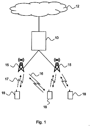
1 of 10 drawing sheets so far from the published document, cropped to the drawing. Every sheet is in the USPTO PDF.
What the patent claimed, word for word. All of it is now free to use.
1.
The present disclosure relates generally to communication, and more specifically for mitigating insufficient attenuation in a wireless communication network.
2.
The 3rd Generation Partnership Project (3GPP) Long Term Evolution (LTE) represents a major advance in cellular technology and is the next step forward in cellular 3G services as a natural evolution of Global System for Mobile communications (GSM) and Universal Mobile Telecommunications System (UMTS). LTE provides for an uplink speed of up to 50 megabits per second (Mbps) and a downlink speed of up to 100 Mbps and brings many technical benefits to cellular networks. LTE is designed to meet carrier needs for high-speed data and media transport as well as high-capacity voice support well into the next decade. Bandwidth is scalable from 1.25 MHz to 20 MHz. This suits the needs of different network operators that have different bandwidth allocations, and also allows operators to provide different services based on spectrum. LTE is also expected to improve spectral efficiency in 3G networks, allowing carriers to provide more data and voice services over a given bandwidth. LTE encompasses high-speed data, multimedia unicast and multimedia broadcast services.
The LTE physical layer (PHY) is a highly efficient means of conveying both data and control information between an enhanced base station (eNodeB) and mobile user equipment (UE). The LTE PHY employs some advanced technologies that are new to cellular applications. These include Orthogonal Frequency Division Multiplexing (OFDM) and Multiple Input Multiple Output (MIMO) data transmission. In addition, the LTE PHY uses Orthogonal Frequency Division Multiple Access (OFDMA) on the downlink (DL) and Single Carrier--Frequency Division Multiple Access (SC-FDMA) on the uplink (UL). OFDMA allows data to be directed to or from multiple users on a subcarrier-by-subcarrier basis for a specified number of symbol periods.
Over-the-air resources are thus used in a manner where orthogonality in time, frequency, and coding seek to minimize interference. In certain frequency band allocations and loading conditions, wireless transmitting/receiving units can be required to transmit and receive channels that are too close to provide an adequate attenuation. In an attempt to address this situation, it has been proposed to limit system bandwidth to provide for co-existence and avoid self-desensitization. However, such limits introduce inefficiencies because of increased overhead and reduced scheduling gains associated to operating independent carriers instead of a wider band allocation.
The following presents a simplified summary in order to provide a basic understanding of some aspects of the disclosed aspects. This summary is not an extensive overview and is intended to neither identify key or critical elements nor delineate the scope of such aspects. Its purpose is to present some concepts of the described features in a simplified form as a prelude to the more detailed description that is presented later.
In one aspect, a method is provided for mitigating inadequate attenuation for co-existence between channels by employing a processor executing computer executable instructions stored on a computer readable storage medium to implement following acts: scheduling via a downlink channel a transmission by a first user equipment on an uplink channel; determining that an uplink frequency band and a first transmit power level used for the transmission by the first user equipment provides an inadequate attenuation to a downlink frequency band on the downlink channel; and changing the scheduling of the transmission on one of the uplink channel and the downlink channel to provide an adequate attenuation to the downlink frequency band.
In another aspect, a computer program product is provided for mitigating inadequate attenuation for co-existence between channels. At least one computer readable storage medium stores computer executable instructions that, when executed by at least one processor, implement components: A first set of codes schedules via a downlink channel a transmission by a first user equipment on an uplink channel. A second set of codes determines that an uplink frequency band and a first transmit power level used for the transmission by the first user equipment provides an inadequate attenuation to a downlink frequency band on the downlink channel. A third set of codes changes the scheduling of the transmission on one of the uplink channel and the downlink channel to provide an adequate attenuation to the downlink frequency band.
In an additional aspect, an apparatus is provided for mitigating inadequate attenuation for co-existence between channels, the apparatus. At least one computer readable storage medium stores computer executable instructions that, when executed by the at least one processor, implement components: Means are provided for scheduling via a downlink channel a transmission by a first user equipment on an uplink channel. Means are provided for determining that an uplink frequency band and a first transmit power level used for the transmission by the first user equipment provides an inadequate attenuation to a downlink frequency band on the downlink channel. Means are provided for changing the scheduling of the transmission on one of the uplink channel and the downlink channel to provide an adequate attenuation to the downlink frequency band.
In another additional aspect, an apparatus is provided for mitigating inadequate attenuation for co-existence between channels. A scheduler schedules via a transmitter on a downlink channel a transmission by a first user equipment received by the receiver on an uplink channel. A computing platform determines that an uplink frequency band and a first transmit power level used for the transmission by the first user equipment provides an inadequate attenuation to a downlink frequency band on the downlink channel, and changes the scheduling of the transmission on one of the uplink channel and the downlink channel to provide an adequate attenuation to the downlink frequency band.
In a further aspect, a method is provided for mitigating inadequate attenuation for co-existence between channels by employing a processor executing computer executable instructions stored on a computer readable storage medium to implement following acts: A downlink channel is received from a serving node for scheduling a transmission by a first user equipment on an uplink channel. A value is determined related to self-interference. A feedback report is transmitted based upon the value for the serving node to determine that an uplink frequency band and a first transmit power level used for the transmission by the first user equipment provides an inadequate attenuation to a downlink frequency band on the downlink channel. A change in the scheduling of the transmission on one of the uplink channel and the downlink channel. The uplink channel is transmitted and the downlink channel is received in accordance with the change.
In yet one aspect, a computer program product is provided for mitigating inadequate attenuation for co-existence between channels. At least one computer readable storage medium stores computer executable instructions that, when executed by at least one processor, implement components: A first set of codes receives a downlink channel from a serving node for scheduling a transmission by a first user equipment on an uplink channel. A second set of codes determines a value related to self-interference. A third set of codes transmits a feedback report based upon the value for the serving node to determine that an uplink frequency band and a first transmit power level used for the transmission by the first user equipment provides an inadequate attenuation to a downlink frequency band on the downlink channel. A fourth set of codes receives a change in the scheduling of the transmission on one of the uplink channel and the downlink channel to provide an adequate attenuation to the downlink frequency band. A fifth set of codes transmits on the uplink channel and receives on the downlink channel in accordance with the change.
In yet another aspect, an apparatus is provided for mitigating inadequate attenuation for co-existence between channels. At least one computer readable storage medium stores computer executable instructions that, when executed by the at least one processor, implement components: Means are provided for receiving a downlink channel from a serving node for scheduling a transmission by a first user equipment on an uplink channel. Means are provided for determining a value related to self-interference. Means are provided for transmitting a feedback report based upon the value for the serving node to determine that an uplink frequency band and a first transmit power level used for the transmission by the first user equipment provides an inadequate attenuation to a downlink frequency band on the downlink channel. Means are provided for receiving a change the scheduling of the transmission on one of the uplink channel and downlink channel to provide an adequate attenuation to the downlink frequency band. Means are provided for transmitting on the uplink channel and receiving on the downlink channel in accordance with the change.
In yet an additional aspect, an apparatus is provided for mitigating inadequate attenuation for co-existence between channels. A receiver receives a downlink channel from a serving node for scheduling a transmission by a first user equipment on an uplink channel. A computing platform determines a value related to self-interference. A transmitter transmits a feedback report based upon the value for the serving node to determine that an uplink frequency band and a first transmit power level used for the transmission by the first user equipment provides an inadequate attenuation to a downlink frequency band on the downlink channel. The receiver receives a change in the scheduling of the transmission on one of the uplink channel and the downlink channel to provide an adequate attenuation to the downlink frequency band. The transmitter transmits on the uplink channel and the receiver receives on the downlink channel in accordance with the change.
In yet another additional aspect, a method is provided for mitigating inadequate attenuation for co-existence between channels by employing a processor executing computer executable instructions stored on a computer readable storage medium to implement following acts: A first transmission is controlled on a first wireless channel. It is determined that a frequency band and a transmit power used for the transmission provides an inadequate attenuation to a second wireless channel. The transmission on the first wireless channel is changed to increase the attenuation to the second wireless channel.
In yet a further aspect, a computer program product is provided for mitigating inadequate attenuation for co-existence between channels. At least one computer readable storage medium stores computer executable instructions that, when executed by at least one processor, implement components: A first set of codes controls a first transmission on a first wireless channel. A second set of codes determines that a frequency band and a transmit power used for the transmission provide inadequate attenuation to a second wireless channel. A third set of codes changes the transmission on the first wireless channel to increase the attenuation to the second wireless channel.
In one aspect, an apparatus is provided for mitigating inadequate attenuation for co-existence between channels. At least one computer readable storage medium stores computer executable instructions that, when executed by the at least one processor, implement components: Means are provided for controlling a first transmission on a first wireless channel. Means are provided for determining that a frequency band and a transmit power used for the transmission provide inadequate attenuation to a second wireless channel. Means are provided for changing the transmission on the first wireless channel to increase the attenuation to the second wireless channel.
In another aspect, an apparatus is provided for mitigating inadequate attenuation for co-existence between channels. A transmitter controls a first transmission on a first wireless channel. A computing platform determines that a frequency band and a transmit power used for the transmission provide inadequate attenuation to a second wireless channel. The transmitter changes the transmission on the first wireless channel to increase the attenuation to the second wireless channel.
To the accomplishment of the foregoing and related ends, one or more aspects comprise the features hereinafter fully described and particularly pointed out in the claims. The following description and the annexed drawings set forth in detail certain illustrative aspects and are indicative of but a few of the various ways in which the principles of the aspects may be employed. Other advantages and novel features will become apparent from the following detailed description when considered in conjunction with the drawings and the disclosed aspects are intended to include all such aspects and their equivalents.
The features, nature, and advantages of the present disclosure will become more apparent from the detailed description set forth below when taken in conjunction with the drawings in which like reference characters identify correspondingly throughout and wherein:
FIG. 1 illustrates a block diagram for a radio access network and user equipment that mitigates inadequate attenuation.
FIG. 2 illustrates a flow diagram of a methodology for mitigating inadequate attenuation in an exemplary broadband radio access network.
FIG. 3 illustrates a diagram of a wireless communication system comprising macro cells, femto cells and pico cells.
FIG. 4 illustrates a diagram of a multiple access wireless communication system.
FIG. 5 illustrates a schematic of a multiple input multiple output (MIMO) communication system.
FIG. 6 illustrates a flow diagram of a methodology for a serving node to mitigate inadequate attenuation.
FIG. 7 illustrates a flow diagram of a methodology for user equipment to mitigate inadequate attenuation.
FIG. 8 illustrates a flow diagram of a methodology for mitigating inadequate attenuation.
FIG. 9 illustrates a block diagram of a logical grouping of electrical components for mitigating inadequate attenuation that is incorporated at least in part in a node.
FIG. 10 illustrates a block diagram of a logical grouping of electrical components for mitigating inadequate attenuation that is incorporated at least in part in user equipment.
FIG. 11 illustrates a block diagram of a logical grouping of electrical components for mitigating inadequate attenuation.
FIG. 12 illustrates a block diagram of an apparatus having means for a serving node to mitigate inadequate attenuation.
FIG. 13 illustrates a block diagram of an apparatus having means for user equipment to mitigate inadequate attenuation.
FIG. 14 illustrates a block diagram of an apparatus having means for mitigating inadequate attenuation.
User equipment (UE) reports periodically or aperiodically (e.g., event triggered) serving cell reference signal received power and quality as well as uplink power headroom information to the serving evolved NodeB (eNB). The eNB calculates a current interference level experienced by the UE from the feedback report and its own loading. Since the self-interference is not flat across frequencies, the tolerable self-interference level depends on downlink scheduling. From the calculated interference, the eNB can calculate uplink allocation parameters. Sequence of scheduling decisions can be downlink allocation, determining tolerable self-interference, and uplink allocation, or in the opposite order, or the downlink and uplink allocation can be jointly determined. An additional scheduling constraint can be derived for meeting the co-existence requirements, which can be determined from the power headroom report alone. Thereby interference to other user equipment or self-interference (self-desensitization) is addressed when inadequate attenuation exists while also allowing deploying full system bandwidth. It should be appreciate that the present innovation applies to adjacent channel Time Division Duplex (TDD) coexistence even without frequency duplex. Further the present innovation has applications to scheduling either or both an uplink and a downlink to achieve greater attenuation.
Various aspects are now described with reference to the drawings. In the following description, for purposes of explanation, numerous specific details are set forth in order to provide a thorough understanding of one or more aspects. It may be evident, however, that the various aspects may be practiced without these specific details. In other instances, well-known structures and devices are shown in block diagram form in order to facilitate describing these aspects.
In FIG. 1, a wireless communication system 100 provides high speed packet access between a Radio Access Network (RAN) 102, which is depicted as a scheduler 104 and an evolved NodeB (eNB) 106, and first and second UEs 108, 110. In an exemplary aspect, the scheduler 104 via a transmitter (Tx) 112 of the serving eNB 106 has scheduled the first and second UEs 108, 110 via a Downlink (DL) channel 114 to use frequency resources on an Uplink (UL) channel 116 that is received by a receiver (Rx) 118 of the eNB 106. The uplink frequency resources are close in frequency to a portion of the Downlink (DL) channel 114 used by the eNB 106 for this scheduling such that inadequate attenuation is provided for at least one of the UEs 108, 110.
In one aspect, the inadequate attenuation means causing self-interference, which causes self-desensitization. For instance, a first downlink grant or assignment 120 is received by a receiver 122 of the first UE 108. This first downlink grant or assignment 120 is for a DL frequency band 124 of the DL channel 114 that is close to an UL frequency band 126 of the UL channel 116. A first uplink grant 128 is given to the first UE 108 to make a transmission via a transmitter 130 on the UL channel 116 in this UL frequency band 126. Thus, the receiver 122 of the first UE 108 turned to the DL frequency band 124 is subject to interference (self-desensitization) 132 from the first UE 108.
In another aspect, the inadequate attenuation means causing interference to another wireless transmitter/receiver unit. For instance, a second uplink grant 134 for the UL frequency band 126 is received by a receiver 136 of the second UE 110. When the second UE 110 transmits using a transmitter 138, interference 140 is caused at the receiver 122 of the first UE 108.
In mitigation of the inadequate attenuation, each UE 108, 110 can utilize a respective computing platform 142, 144 that generate downlink channel feedback reports 146, transmitted either periodically or aperiodically (e.g., event triggered). The feedback reports 146 can pertain to a transmit power (e.g., headroom) used by the respective UE 108, 110. Alternatively or in addition, the feedback reports 146 can indicate downlink channel received strength from the eNB 106. Alternatively or in addition, the feedback reports 146 can indicate channel quality (e.g., power/location of interference signals received from other base stations).
The eNB 106 can utilize a computing platform 148 to determine that inadequate attenuation exists, such as based upon scheduling and estimates of characteristics of the UEs 108, 110. Alternatively or in addition, the eNB 106 can receive the feedback reports 146 to aid or to primarily be a basis for determining the inadequate attenuation. Based upon this determination, the eNB 106 can make changes in scheduling, depicted as sending another grant 150 with either a lower transmit power value or changed frequency band.
In an exemplary aspect, one problem when using broadband systems such as LTE is that some of the existing bands do not provide an adequate attenuation. There are two types of problems that can occur. For user equipment (UEs) that transmit at the Uplink (UL) channel closest to the Downlink (DL) band, the general -50 dBm/MHz coexistence requirements is not met. When the UE transmits at maximum power, the required attenuation is approximately 60-70 dB. Assuming a 35 dB-45 dB duplexer attenuation, in the worst case, a level of up to 35 dB noise attenuation is still required in order to meet the coexistence requirements. In order to achieve this, the duplex gap should be more than at least the UE transmission bandwidth. This condition may not be satisfied in all cases. The coexistence requirements apply to receive frequencies of other bands as well, and similarly, the frequency separation between the UL frequency and the receive frequency of any other band should be more than at least the UE transmission bandwidth. This condition may also not be satisfied in all cases.
The other type of problem is when the UE transmission causes self-desensitization. In order to avoid desensitization, the Transmit (Tx) leakage into the Receive (Rx) frequency should be no more than -105 dBm/MHz, preferably no more than -115 dBm/MHz. Again, assuming 35 dB duplexer attenuation, the Tx noise floor at the receive frequency should be around -70 dBm/MHz. In order to achieve this, the duplex separation should be at least five times the UE transmission bandwidth.
Both the coexistence problems or the self-desensitization can be caused by other sources of unwanted spurious products besides Tx spectral re-growth. A well known example is when transmission with a narrow band allocation intermodulates with the carrier leakage (LO leakage) or with the IQ-image. This will create 3.sup.rd order, 5.sup.th order or higher order intermodulation products that can be outside of the UL channel depending on the scheduled UL frequency allocation. Both LO leakage and IQ-image are artifacts created by imperfect modulators used in upconverting the baseband signal to RF frequencies. There are other effects creating spurious emissions at the same frequency locations. The location in frequency and the approximate power of these emissions can be estimated by the eNB if the eNB has information about the scheduled UL frequency and the Tx power.
Assuming broadband LTE frequency allocation (10 MHz, 15 MHz, 20 MHz), there will be operating bands where one or both problems described above will occur.
In an exemplary aspect depicted in FIG. 2, a methodology 200 is provided to alleviate the aforementioned problems, and in particular for mitigating inadequate attenuation. The UE reports serving cell RSRP (Reference Signal Received Power), RSRQ (Reference Signal Received Quality), and UL power headroom information to a serving eNB (evolved or EUTRAN NodeB) (block 202). The report can be periodic or event triggered, where the event is some parameters exceeding certain thresholds (block 204). The eNB can then calculate the current interference level experienced by the UE from the reported RSRP and RSRQ levels, and further considering the eNBs own loading (block 206). The loading factor L indicates RSRP/IOR ratio (in dB notation RSRP(dBm)-IOR(dBm)), which is used in calculating the interference level (block 208). Intra-cell received power (IOR) is generally regarded as the total received signal power in a time slot from the Base Station (BS) in which the Wireless Transmit/Receive Unit (WTRU) (e.g., UE) is communicating (as opposed to Inter-cell interference (IOC), generally defined as the sum of the total received signal power in a given time-slot from all the neighboring base stations). Intra-cell received power (IOR) is, therefore, the "useful" energy, or the signal from the BS with which a UE is communicating. Inter-cell interference is the interference caused by all the undesired signal energy from all the other Base Stations (BSs) received by a WTRU, and is therefore detrimental to the decoding of the "useful" signal. RSRQ is RSRP(dBm)-RSSI(dBm) where RSSI is the total received power (block 212)
It should be understood that while RSRP, RSRQ, Location (LOC), and IOC are used to determine as examples provided may use the above mentioned quantities to perform reselection ranking measurements, these quantities may be substituted by any other suitable signal power or signal quality measure without falling outside the intended scope of this disclosure. One skilled in the art with the benefit of the present disclosure would recognize that if any other measurements were used in the cell reselection process, the concepts disclosed herein would be equally applicable to such other measurements and thereby fall within the scope of this specification as well.
Assuming a targeted desensitization limit, the eNB can calculate level of tolerable self-interference for the UE (block 210). In one aspect, the tolerable total interference is RSRP(dBm)-SNR(dB) where SNR is the required SNR for demodulation. The tolerable self-interference is generally the total tolerable interference minus thermal noise minus received interference by the UE from other base stations. The thermal noise can be estimated by using a typical receiver noise figure. The received interference from other base stations, IOC, is IOC=10log.sub.10 (10.sup.RSRP(dBm)/10-RSRQ(dBm)/10-10.sup.RSRP(dBm)/10-L/10)-N(dBm) where N(dBm) is the thermal noise floor, L=RSRP(dBm)-IOR(dBm), is the serving cell loading factor, which equals the transmit reference signal power to total eNB transmit power ratio in dB. The loading factor L is known to the eNB even without UE reports. Therefore, with the knowledge of RSRP, RSRQ, L, the target SNR and the receiver noise figure, the tolerable self-interference can be calculated. The definition of the parameters mentioned above may involve various scaling factors but those were omitted here for simplicity.
Since the self-interference is not flat across frequencies, the tolerable self-interference level will also depend on the current downlink scheduling. From the calculated interference, the eNB can calculate the UL allocation parameters (block 214). UL allocation parameters may include, for example in block 216:
Start Resource Block (RB), the lowest frequency of the set of allocated RBs;
Number of RB, the total number of RBs allocated to the UE (i.e., bandwidth); and
Power control to set Tx power.
Since the eNB knows what transmit power and frequency allocation the UE will be using, it can estimate how much self-interference will be generated based on calculations that assume typical power amplifier (PA) characteristics and typical duplexer isolation (block 218). In this calculation, the eNB can use the reported headroom and the recent power control commands, if any, that was sent to the UE (block 220). The reported headroom is generally defined as the maximum power available for transmission minus the current transmission power. In one aspect, the sequence of scheduling decisions may comprise DL allocation, followed by determining tolerable self-interference, then UL allocation (block 222).
In another aspect, this process is reversed. In yet another aspect, the DL and UL allocation can be jointly determined using the available information. An additional scheduling constraint can be derived for meeting the coexistence requirements. This can be determined from the power headroom report alone. The additional scheduling constraint, in one aspect, is defined as the base station further lowering the UE transmit power by using power control or schedules the uplink transmission in a more preferable location in the spectrum, beyond what would be required just to meet the self-interference target.
By virtue of the foregoing, in one aspect an apparatus is provided that is operable in wireless communication system. Means are provided for receiving an RSRP and an RSRQ from a UE. Means are provided for calculating a level of tolerable self-interference for the UE based on the RSRP and RSRQ. Means are provided for calculating an uplink parameter for the UE based on the calculated level of tolerable self-interference. Means are provided for transmitting the uplink parameter to the UE.
In another aspect, a method is provided for use in a wireless communication system by receiving an RSRP and an RSRQ from a UE, calculating a level of tolerable self-interference for the UE based on the RSRP and RSRQ, calculating an uplink parameter for the UE based on the calculated level of tolerable self-interference, and transmitting the uplink parameter to the UE. An electronic device can be configured to execute this method.
In an additional aspect, a machine-readable medium comprises instructions which, when executed by a machine, cause the machine to perform operations including: (a) receiving an RSRP and an RSRQ from a UE; (b) calculating a level of tolerable self-interference for the UE based on the RSRP and RSRQ; (c) calculating an uplink parameter for the UE based on the calculated level of tolerable self-interference; and (d) transmitting the uplink parameter to the UE.
In a further aspect, an apparatus is provided that is operable in a wireless communication system: A processor is configured for receiving an RSRP and an RSRQ from a UE, for calculating a level of tolerable self-interference for the UE based on the RSRP and RSRQ, for calculating an uplink parameter for the UE based on the calculated level of tolerable self-interference, and for transmitting the uplink parameter to the UE. A memory can be coupled to the processor for storing data.
In some aspects the teachings herein may be employed in a network that includes macro scale coverage (e.g., a large area cellular network such as a 3G (Third Generation) networks, typically referred to as a macro cell network) and smaller scale coverage (e.g., a residence-based or building-based network environment). As an access terminal ("AT") moves through such a network, the access terminal may be served in certain locations by access nodes ("ANs") that provide macro coverage while the access terminal may be served at other locations by access nodes that provide smaller scale coverage. In some aspects, the smaller coverage nodes may be used to provide incremental capacity growth, in-building coverage, and different services (e.g., for a more robust user experience). In the discussion herein, a node that provides coverage over a relatively large area may be referred to as a macro node. A node that provides coverage over a relatively small area (e.g., a residence) may be referred to as a femto node. A node that provides coverage over an area that is smaller than a macro area and larger than a femto area may be referred to as a pico node (e.g., providing coverage within a commercial building).
A cell associated with a macro node, a femto node, or a pico node may be referred to as a macro cell, a femto cell, or a pico cell, respectively. In some implementations, each cell may be further associated with (e.g., divided into) one or more sectors.
In various applications, other terminology may be used to reference a macro node, a femto node, or a pico node. For example, a macro node may be configured or referred to as an access node, base station, access point, eNodeB, macro cell, and so on. Also, a femto node may be configured or referred to as a Home NodeB, Home eNodeB, access point base station, femto cell, and so on.
In the example shown in FIG. 3, base stations 310a, 310b and 310c may be macro base stations for macro cells 302a, 302b and 302c, respectively. Base station 310x may be a pico base station for a pico cell 302x communicating with terminal 320x. Base station 310y may be a femto base station for a femto cell 302y communicating with terminal 320y. Although not shown in FIG. 3 for simplicity, the macro cells may overlap at the edges. The pico and femto cells may be located within the macro cells (as shown in FIG. 3) or may overlap with macro cells and/or other cells.
Wireless network 300 may also include relay stations, e.g., a relay station 310z that communicates with terminal 320z. A relay station is a station that receives a transmission of data and/or other information from an upstream station and sends a transmission of the data and/or other information to a downstream station. The upstream station may be a base station, another relay station, or a terminal. The downstream station may be a terminal, another relay station, or a base station. A relay station may also be a terminal that relays transmissions for other terminals. A relay station may transmit and/or receive low reuse preambles. For example, a relay station may transmit a low reuse preamble in similar manner as a pico base station and may receive low reuse preambles in similar manner as a terminal.
A network controller 330 may couple to a set of base stations and provide coordination and control for these base stations. Network controller 330 may be a single network entity or a collection of network entities. Network controller 330 may communicate with base stations 310 via a backhaul. Backhaul network communication 334 can facilitate point-to-point communication between base stations 310a-310c employing such a distributed architecture. Base stations 310a-310c may also communicate with one another, e.g., directly or indirectly via wireless or wireline backhaul.
Wireless network 300 may be a homogeneous network that includes only macro base stations (not shown in FIG. 3). Wireless network 300 may also be a heterogeneous network that includes base stations of different types, e.g., macro base stations, pico base stations, home base stations, relay stations, etc. These different types of base stations may have different transmit power levels, different coverage areas, and different impact on interference in wireless network 300. For example, macro base stations may have a high transmit power level (e.g., 20 Watts) whereas pico and femto base stations may have a low transmit power level (e.g., 9 Watt). The techniques described herein may be used for homogeneous and heterogeneous networks.
Terminals 320 may be dispersed throughout wireless network 300, and each terminal may be stationary or mobile. A terminal may also be referred to as an access terminal (AT), a mobile station (MS), user equipment (UE), a subscriber unit, a station, etc. A terminal may be a cellular phone, a personal digital assistant (PDA), a wireless modem, a wireless communication device, a handheld device, a laptop computer, a cordless phone, a wireless local loop (WLL) station, etc. A terminal may communicate with a base station via the downlink and uplink. The downlink (or forward link) refers to the communication link from the base station to the terminal, and the uplink (or reverse link) refers to the communication link from the terminal to the base station.
A terminal may be able to communicate with macro base stations, pico base stations, femto base stations, and/or other types of base stations. In FIG. 3, a solid line with double arrows indicates desired transmissions between a terminal and a serving base station, which is a base station designated to serve the terminal on the downlink and/or uplink. A dashed line with double arrows indicates interfering transmissions between a terminal and a base station. An interfering base station is a base station causing interference to a terminal on the downlink and/or observing interference from the terminal on the uplink.
Wireless network 300 may support synchronous or asynchronous operation. For synchronous operation, the base stations may have the same frame timing, and transmissions from different base stations may be aligned in time. For asynchronous operation, the base stations may have different frame timing, and transmissions from different base stations may not be aligned in time. Asynchronous operation may be more common for pico and femto base stations, which may be deployed indoors and may not have access to a synchronizing source such as a Global Positioning System (GPS).
In one aspect, to improve system capacity, the coverage area 302a, 302b, or 302c corresponding to a respective base station 310a-310c can be partitioned into multiple smaller areas (e.g., areas 304a, 304b, and 304c). Each of the smaller areas 304a, 304b, and 304c can be served by a respective base transceiver subsystem (BTS, not shown). As used herein and generally in the art, the term "sector" can refer to a BTS and/or its coverage area depending on the context in which the term is used. In one example, sectors 304a, 304b, 304c in a cell 302a, 302b, 302c can be formed by groups of antennas (not shown) at base station 310, where each group of antennas is responsible for communication with terminals 320 in a portion of the cell 302a, 302b, or 302c. For example, a base station 310 serving cell 302a can have a first antenna group corresponding to sector 304a, a second antenna group corresponding to sector 304b, and a third antenna group corresponding to sector 304c. However, it should be appreciated that the various aspects disclosed herein can be used in a system having sectorized and/or unsectorized cells. Further, it should be appreciated that all suitable wireless communication networks having any number of sectorized and/or unsectorized cells are intended to fall within the scope of the hereto appended claims. For simplicity, the term "base station" as used herein can refer both to a station that serves a sector as well as a station that serves a cell. It should be appreciated that as used herein, a downlink sector in a disjoint link scenario is a neighbor sector. While the following description generally relates to a system in which each terminal communicates with one serving access point for simplicity, it should be appreciated that terminals can communicate with any number of serving access points.
In some aspects, a restricted femto node (which may also be referred to as a Closed Subscriber Group Home NodeB) is one that provides service to a restricted provisioned set of access terminals. This set may be temporarily or permanently extended as necessary. In some aspects, a Closed Subscriber Group ("CSG") may be defined as the set of access nodes (e.g., femto nodes) that share a common access control list of access terminals. A channel on which all femto nodes (or all restricted femto nodes) in a region operate may be referred to as a femto channel.
Various relationships may thus exist between a given femto node and a given access terminal or user equipment. For example, from the perspective of an access terminal, an open femto node may refer to a femto node with no restricted association. A restricted femto node may refer to a femto node that is restricted in some manner (e.g., restricted for association and/or registration). A home femto node may refer to a femto node on which the access terminal is authorized to access and operate on. A guest femto node may refer to a femto node on which an access terminal is temporarily authorized to access or operate on. An alien femto node may refer to a femto node on which the access terminal is not authorized to access or operate on, except for perhaps emergency situations (e.g., 911 calls).
The description continues in the full USPTO document.
About 6,214 words. The USPTO PDF has it with every drawing.
Fees are due 3.5, 7.5 and 11.5 years after grant. This patent expired on December 10, 2025, so the fee marked "not paid" was the one that went unpaid.
POWER HEADROOM-SENSITIVE SCHEDULING
Filed Nov 2009 · published May 2010Power headroom-sensitive scheduling
Filed Nov 2009 · granted Dec 2013Earlier publications, parents and continuations. None of them can still be enforced, or this patent would not be listed.
Prior art cited by the examiner or applicant. Useful when you check your own idea for novelty.
Everything on this page comes from the documents linked above.