Lapsed, fee not paid25 drawings
Medical Devices · US 8,603,111 B2
Ligating apparatus
A ligating apparatus including a thread receiving portion movably disposed at a distal end of an inserting part body.
US 8,603,128 B2 · Assignee: MicroVention, Inc. · Inventors: Greene, Jr.; George R. et al.
Sheet 1 of 13 from the published document. All sheets in the USPTO PDF
An embolization device for occluding a body cavity includes one or more elongated, expansible, hydrophilic embolizing elements non-releasably carried along the length of an elongated filamentous carrier that is preferably made of a very thin, highly flexible filament or microcoil of nickel/titanium alloy. At least one expansile embolizing element is non-releasably attached to the carrier. A first embodiment includes a plurality of embolizing elements fixed to the carrier at spaced-apart intervals along its length. In second, third and fourth embodiments, an elongate, continuous, coaxial embolizing element is non-releasably fixed to the exterior surface of the carrier, extending along a substantial portion of the length of the carrier proximally from a distal tip, and optionally includes a lumenal reservoir for delivery of therapeutic agents. Exemplary methods for making these devices include skewering and molding the embolizing elements. In any of the embodiments, the embolizing elements may be made of a hydrophilic, macroporous, polymeric, hydrogel foam material. In the second, third and fourth embodiments, the elongate embolizing element is preferably made of a porous, environmentally-sensitive, expansile hydrogel, which can optionally be made biodegradable and/or bioresorbable, having a rate of expansion that changes in response to a change in an environmental parameter, such as the pH or temperature of the environment.
The present invention relates to devices for the occlusion of body cavities, such as in the embolization of vascular aneurysms and the like, and methods for making and using such devices. More specifically, the present invention relates to a device that is inserted into a body cavity, such as an aneurysm, to occlude the cavity by creating an embolism therein, a method for making the device, and a method for embolizing a body cavity using the device. The occlusion of body cavities, blood vessels and other lumina by embolization is desired in a number of clinical situations. For example, the occlusion of fallopian tubes for the purposes of sterilization, and the occlusive repair of cardiac defects, such as a patent foramen ovale, patent ductus arteriosis, and left atrial appendage and atrial septal defects. The function of an occlusion device in such situations is to substantially block th
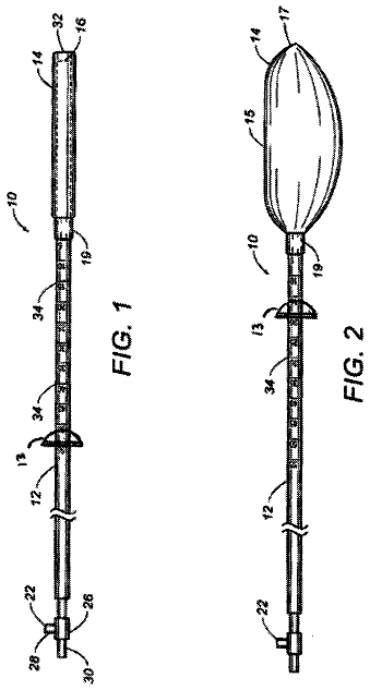
1 of 13 drawing sheets so far from the published document, cropped to the drawing. Every sheet is in the USPTO PDF.
What the patent claimed, word for word. All of it is now free to use.
Not Applicable
The present invention relates to devices for the occlusion of body cavities, such as in the embolization of vascular aneurysms and the like, and methods for making and using such devices. More specifically, the present invention relates to a device that is inserted into a body cavity, such as an aneurysm, to occlude the cavity by creating an embolism therein, a method for making the device, and a method for embolizing a body cavity using the device.
The occlusion of body cavities, blood vessels and other lumina by embolization is desired in a number of clinical situations. For example, the occlusion of fallopian tubes for the purposes of sterilization, and the occlusive repair of cardiac defects, such as a patent foramen ovale, patent ductus arteriosis, and left atrial appendage and atrial septal defects. The function of an occlusion device in such situations is to substantially block the flow of body fluids into or through the cavity, lumen, vessel, space or defect for the therapeutic benefit of the patient.
Vascular embolization has been used to control vascular bleeding, to occlude the blood supply to tumors, and to occlude vascular aneurysms, particularly intracranial aneurysms. In recent years, vascular embolization for the treatment of aneurysms has received much attention. Several different treatment modalities have been employed in the prior art. U.S. Pat. No. 4,819,637--Dornandy, Jr. et al., for example, describes a vascular embolization system that employs a detachable balloon delivered to the aneurysm site by an intravascular catheter. The balloon is carried into the aneurysm at the tip of the catheter, and is inflated inside the aneurysm with a solidifying fluid (typically a polymerizable resin or gel) to occlude the aneurysm. The balloon is then detached from the catheter by gentle traction on the catheter. While the balloon-type embolization device can provide an effective occlusion of many types of aneurysms or other body cavities, it is difficult to retrieve or move after the solidifying fluid sets, and it is difficult to visualize unless it is filled with a contrast material. Furthermore, there are risks of balloon rupture during inflation and of premature detachment of the balloon from the catheter.
Another approach is the direct injection of a liquid polymer embolic agent into the cavity or vascular site to be occluded. One type of liquid polymer used in the direct injection technique is a rapidly polymerizing liquid, such as a cyanoacrylate resin, particularly isobutyl cyanoacrylate, that is delivered to the target site as a liquid, and then is polymerized in situ. Alternatively, a liquid polymer that is precipitated at the target site from a carrier solution has been used. An example of this type of embolic agent is a cellulose acetate polymer mixed with bismuth trioxide and dissolved in dimethyl sulfoxide (DMSO). Another type is ethylene vinyl alcohol dissolved in DMSO. On contact with blood, the DMSO diffuses out, and the polymer precipitates out and rapidly hardens into an embolic mass that conforms to the shape of the aneurysm. Other examples of materials used in this "direct injection" method are disclosed in the following U.S. Pat. Nos. 4,551,132--Pasztor et al.; 4,795,741--Leshchiner et al.; 5,525,334--Ito et al.; and 5,580,568--Greff et al.
The direct injection of liquid polymer embolic agents has proven difficult in practice. For example, migration of the polymeric material from the aneurysm and into the adjacent blood vessel has presented a problem. In addition, visualization of the embolization material requires that a contrasting agent be mixed with it, and selecting embolization materials and contrasting agents that are mutually compatible may result in performance compromises that are less than optimal. Furthermore, precise control of the deployment of the polymeric embolization material is difficult, leading to the risk of improper placement and/or premature solidification of the material. Moreover, once the embolization material is deployed and solidified, it is difficult to move or retrieve.
Another approach that has shown promise is the use of thrombogenic microcoils. These microcoils may be made of a biocompatible metal alloy (typically, platinum and tungsten) or a suitable polymer. If made of metal, the coil may be provided with Dacron fibers to increase thrombogenicity. The coil is deployed through a microcatheter to the vascular site. Examples of microcoils are disclosed in the following U.S. Pat. Nos. 4,994,069--Ritchart et al.; 5,133,731--Butler et al.; 5,226,911'Chee et al.; 5,312,415--Palermo; 5,382,259--Phelps et al.; 5,382,260--Dormandy, Jr. et al.; 5,476,472--Dormandy, Jr. et al.; 5,578,074--Mirigian; 5,582,619--Ken; 5,624,461--Mariant; 5,645,558--Horton; 5,658,308--Snyder; and 5,718,711--Berenstein et al.
The microcoil approach has met with some success in treating small aneurysms with narrow necks, but the coil must be tightly packed into the aneurysm to avoid shifting that can lead to recanalization. Microcoils have been less successful in the treatment of larger aneurysms, especially those with relatively wide necks. A disadvantage of microcoils is that they are not easily retrievable; if a coil migrates out of the aneurysm, a second procedure to retrieve it and move it back into place is necessary. Furthermore, complete packing of an aneurysm using microcoils can be difficult to achieve in practice.
A specific type of microcoil that has achieved a measure of success is the Guglielmi Detachable Coil ("GDC"), described in U.S. Pat. No. 5,122,136--Guglielmi et al. The GDC employs a platinum wire coil fixed to a stainless steel delivery wire by a solder connection. After the coil is placed inside an aneurysm, an electrical current is applied to the delivery wire, which electrolytically disintegrates the solder junction, thereby detaching the coil from the delivery wire. The application of the current also creates a positive electrical charge on the coil, which attracts negatively-charged blood cells, platelets, and fibrinogen, thereby increasing the thrombo-genicity of the coil. Several coils of different diameters and lengths can be packed into an aneurysm until the aneurysm is completely filled. The coils thus create and hold a thrombus within the aneurysm, inhibiting its displacement and its fragmentation.
The advantages of the GDC procedure are the ability to withdraw and relocate the coil if it migrates from its desired location, and the enhanced ability to promote the formation of a stable thrombus within the aneurysm. Nevertheless, as in conventional microcoil techniques, the successful use of the GDC procedure has been substantially limited to small aneurysms with narrow necks.
Still another approach to the embolization of an abnormal vascular site is the injection into the site of a biocompatible "hydrogel," such as poly (2-hydroxyethyl methacrylate) ("pHEMA" or "PHEMA"); or a polyvinyl alcohol foam ("PAF"). See, e.g., Horak et al., "Hydrogels in Endovascular Embolization. II. Clinical Use of Spherical Particles", Biomaterials, Vol. 7, pp. 467-470 (November, 1986); Rao et al., "Hydrolysed Microspheres from Cross-Linked Polymethyl Methacrylate", J. Neuroradiol., Vol. 18, pp. 61-69 (1991); Latchaw et al., "Polyvinyl Foam Embolization of Vascular and Neoplastic Lesions of the Head, Neck, and Spine", Radiology, Vol. 131, pp. 669-679 (June, 1979). These materials are delivered as microparticles in a carrier fluid that is injected into the vascular site, a process that has proven difficult to control.
A further development has been the formulation of the hydrogel materials into a preformed implant or plug that is installed in the vascular site or other body cavity by means such as a microcatheter. See, e.g., U.S. Pat. No. 5,258,042--Mehta. These types of plugs or implants are primarily designed for obstructing blood flow through a tubular vessel or the neck of an aneurysm, and they are not easily adapted for precise implantation within a sac-shaped vascular structure, such as an aneurysm, so as to fill substantially the entire volume of the structure.
U.S. Pat. No. 5,823,198--Jones et al. discloses an expansible PVA foam plug that is delivered to the interior of an aneurysm at the end of a guidewire. The plug comprises a plurality of pellets or particles that expand into an open-celled structure upon exposure to the fluids within the aneurysm so as to embolize the aneurysm. The pellets are coated with a blood-soluble restraining agent to maintain them in a compressed state and attached to the guidewire until delivered to the aneurysm. Because there is no mechanical connection between the pellets and the guidewire (other than the relatively weak temporary bond provided by the restraining agent), however, premature release and migration of some of the pellets remains a possibility.
There has thus been a long-felt, but as yet unsatisfied need for a device for effective occlusive treatment of aneurysms and other body cavities, and a method that can substantially fill aneurysms and other body cavities of a large range of sizes, configurations, and neck widths with an occlusive and/or thrombogenic medium with a minimal risk of inadvertent tissue damage, aneurysm rupture or blood vessel wall damage. There has been a further need for such a method and device that also allow for the precise locational deployment of the medium, while also minimizing the potential for migration away from the target location. In addition, a method and device meeting these criteria should also be relatively easy to use in a clinical setting. Such ease of use, for example, should preferably include a provision for good visualization of the device during and after deployment in a body cavity, lumen or aneurysm.
Broadly, an embolization device, according to a first aspect of the present invention, comprises one or more expansible, hydrophilic embolizing elements non-releasably carried along the length of a filamentous carrier. In a first preferred embodiment, the carrier is a suitable length of very thin, highly flexible filament of nickel/titanium alloy (Nitinol). A plurality of embolizing elements are spaced along the length of the carrier and are separated from each other on the carrier by radiopaque spacers in the form of highly flexible microcoils made of platinum or platinum/tungsten alloy, as in the thrombogenic microcoils of the prior art, as described above.
In a second preferred embodiment, the carrier comprises a continuous length of highly flexible, hollow microcoil made of a biocompatible metal (preferably platinum or platinum/tungsten alloy), with an optional core in the form of a continuous length of thin, highly flexible metal wire, preferably of a shape memory metal alloy such as Nitinol. Alternatively, the carrier may be a suitable length of flexible wire, cable, braid, or other construction that yields the desired flexibility. The carrier is preferably made of a biocompatible metal so as to be visible by means of X-rays or other visualization techniques known in the art, but it also may be made of a suitable polymer that is visible (or is rendered visible) through any of the known visualization methods. The carrier should have sufficient column strength to allow the device to be pushed through a microcatheter.
In the second preferred embodiment, an elongate, continuous, coaxial embolizing element is non-releasably fixed to the exterior surface of the carrier, extending along a substantial portion of the length of the carrier proximally from a distal tip.
In a third exemplary embodiment of an embolization device, the carrier comprises an elongated, filamentous carrier, and the embolizing element comprises a coaxial member of an expansile, hydrophilic polymer, or hydrogel, encapsulating at least a portion of the carrier's length. In a variant incorporating a tubular carrier, such as an tubular braid or the flexible, hollow microcoil described above, the coaxial polymer member is formed such that the lumen of the carrier is substantially void of the polymer, thereby defining an axial reservoir in the carrier. The reservoir constitutes a chamber in which therapeutic agents, e.g., medications, can be placed for delivery to a patient via implantation of the device in a cavity in the patient's body.
A fourth exemplary embodiment of the embolization device is similar in most respects to the third embodiment described above, except that, in one possible variant thereof in which the carrier comprises a flexible tube, the hydrophilic polymer of the coaxial embolizing member encapsulating the carrier also substantially fills the lumen of the carrier, such that the entire surface of the encapsulated portion of the carrier is in contact with the polymer of the embolizing member and no reservoir is created in the carrier.
A first exemplary embodiment of a method for making the third embodiment of the embolization device comprises the provision of a softened, elongated embolizing member of hydrogel supported in a tubular holder. In one possible embodiment of the method, a stiff, elongated support mandrel is inserted coaxially in the lumen of a tubular carrier, such as a helical coil, to straighten and stiffen it, and the soft polymer member is then coaxially skewered with the carrier-and-mandrel, such that the polymer member coaxially encapsulates at least a portion of the length of the carrier. The skewered polymer member is then ejected from the tubular holder and dehydrated in a hygroscopic bath, e.g., alcohol, to remove water from, and thereby shrink, the coaxial polymer embolizing member to a size suitable for passage through the lumen of a catheter.
After dehydration, the polymer member is treated, e.g., in an acid bath, to set the rate of hydration of the polymer, and hence, the rate of expansion of the member, in an aqueous environment, e.g., blood, in response to the level of a physical parameter of the environment, e.g., its temperature or pH level. After the hydration rate of the device is set, it is washed to remove any processing impurities, dried by heating, e.g., in an oven, and then packaged in a sterile container.
A second exemplary embodiment of a method for making the fourth embodiment of the embolization device comprises the provision of a mold having an elongated cavity therein. An elongated filamentous carrier, which may comprise a tubular carrier, as above, is disposed coaxially within the cavity of the mold. In one advantageous variant in which a tightly-coiled helical carrier is employed, the carrier is elastically stretched along its axis, such that the coils are held spaced apart from each other by the mold before disposition therein. In another possible variant, the coils of a helical carrier are formed permanently spaced apart, i.e., without being elastically stretched in the mold. In yet another possible variant, a mandrel is inserted in the lumen of a tubular carrier, in a manner similar to that described above in connection with the first method.
After the carrier is disposed coaxially within the cavity of the mold, a quantity of a softened, expansile, hydrophilic polymer is transferred into the mold under pressure, such that the polymer is molded by the cavity into an embolization member that coaxially encapsulates at least a portion of the length of the carrier. In those variants in which the carrier comprises a tubular carrier that is not internally supported by a lumenal mandrel, the polymer is also caused to flow into the lumen of the carrier, substantially filling it.
After the polymer member is molded onto the carrier, the device is released from the mold, which enables the adjacent coils of an elastically stretched helical carrier to spring back axially into contact with one another through the still-soft polymer member. In those variants incorporating a tubular carrier internally supported by a lumenal mandrel, the mandrel is removed to define a lumenal reservoir in the device for the disposition of therapeutic agents, as in the first exemplary method above. Indeed, the post-molding processes applied to the device are substantially the same as those applied to the device in the first method embodiment described above, including dehydration of the coaxial member, adjustment of its rate of hydration, and the washing, drying and packaging of the device.
The second exemplary method embodiment of the invention is thus capable of making substantially the same embodiments of the embolization device as are made by the first method embodiment, including those with an axial reservoir, as well as other variants of the device, including those having no axial reservoir, and in which the entire surface, including any internal surface, of the encapsulated portion of the carrier is in contact with the polymer of the expansile, coaxial embolizing member.
In both the first and second exemplary methods, the lumenal support mandrel can be removed from the carrier at any stage of the process after the skewered or molded coaxial member is ejected from the holder or mold and before the dried and finished device is packaged. Removal of the mandrel creates a lumenal reservoir in the carrier that, as described above, can be used as a reservoir for the delivery of therapeutic agents, e.g., medications, blood cells, and the like, to a patient via the device. Thus, one possible embodiment of a method for delivering a therapeutic agent to a patient may comprise making an embolization device having an axial reservoir in accordance with either the first or second exemplary methods, disposing a therapeutic agent in the reservoir of the device, and implanting the device in a body cavity of the patient.
Moreover, in both the third and fourth exemplary embodiments of the device, the flexibility, size, and lubricity of the hydrophilic polymer of the coaxial member, and hence, the device itself, all increase with the degree of hydration of the polymer. In accordance with one exemplary embodiment of this invention, the rate of hydration of the polymer in an aqueous environment is, as described above, set during manufacture to a specific value in response to a corresponding specific level of a physical parameter of the environment, e.g., its pH level.
Thus, in one possible embodiment of a method for preparing a fully dehydrated device for insertion into a body cavity via a catheter, the dry device is first immersed in an aqueous medium, e.g., a saline solution, having a relatively low pH level, such that the rate of hydration of the coaxial polymer member in the medium is correspondingly slow. This increases the flexibility and lubricity of the device such that it can be easily inserted into and moved through the lumen of the catheter and into the body cavity, but at a rate that is slow enough to afford the physician ample time to implant the device without allowing it to expand to a size that cannot be inserted into or moved easily through the catheter. However, once the device is emplaced in the cavity, its rate of hydration increases substantially in response to the increased pH level of the surrounding physiological aqueous environment, i.e., blood or plasma, such that the coaxial embolizing member of the device then expands correspondingly rapidly to occlude the cavity.
In yet other embodiments of the embolization device incorporating embolizing elements of hydrogel, the formulation of the polymer of the coaxial member can be modified to incorporate polymers that degrade, or break down, in the body after a period of time in response to, e.g., hydrolysis or enzymatic action, into simpler molecular constituents that can be absorbed by the patient's body and/or eliminated from it as waste. Thus, in another possible embodiment of the device incorporating a hydrogel embolizing member, the member can be made such that it is biodegradable and/or bioresorbable in the patient's body.
In either of the first two preferred embodiments, the embolizing elements may be made of a hydrophilic, macroporous, polymeric, hydrogel foam material, in particular a swellable foam matrix formed as a macroporous solid comprising a foam stabilizing agent and a polymer or copolymer of a free radical polymerizable hydrophilic olefin monomer cross-linked with up to about 10% by weight of a multiolefin-functional cross-linking agent. Such a material is described in U.S. Pat. No. 5,750,585--Park et al., the disclosure of which is incorporated herein by reference. The material may be modified, or provided with additives, to make the implant visible by conventional imaging techniques.
In the second, third and fourth preferred embodiments, the elongate coaxial embolizing element is preferably made of a porous, environmentally-sensitive, expansile hydrogel, of the type described in prior co-pending U.S. patent application Ser. No. 09/804,935, assigned to the assignee of this application and of the invention disclosed and claimed herein. Application Ser. No. 09/804,935 (the disclosure of which is incorporated herein by reference) discloses hydrogels that experience an increase in lubricity and undergo controlled volumetric expansion at a rate that changes in response to changes in such environmental parameters as pH or temperature. These hydrogels are prepared by forming a liquid mixture that contains (a) at least one monomer and/or polymer, at least a portion of which is sensitive to changes in an environmental parameter; (b) a cross-linking agent; and (c) a polymerization initiator. If desired, a porosigen (e.g., NaCl, ice crystals, or sucrose) may be added to the mixture, and then removed from the resultant solid hydrogel to provide a hydrogel with sufficient porosity to permit cellular ingrowth.
The controlled rate of expansion is provided through the incorporation of ethylenically unsaturated monomers with ionizable functional groups (e.g., amines, carboxylic acids). For example, if acrylic acid is incorporated into the crosslinked network, the hydrogel is incubated in a low pH solution to protonate the carboxylic acids. After the excess low pH solution is rinsed away and the hydrogel dried, the hydrogel can be introduced through a microcatheter filled with saline at physiological pH or with blood. The hydrogel cannot expand until the carboxylic acid groups deprotonate. Conversely, if an amine-containing monomer is incorporated into the crosslinked network, the hydrogel is incubated in a high pH solution to deprotonate the amines. After the excess high pH solution is rinsed away and the hydrogel dried, the hydrogel can be introduced through a microcatheter filled with saline at physiological pH or with blood. The hydrogel cannot expand until the amine groups protonate.
Alternatively, in the second preferred embodiment, the elongate coaxial embolizing element may be in the form of a stretch-resistant outer layer applied to the exterior of the carrier along a substantial portion of the length of the carrier. The stretch-resistant outer layer is preferably formed of an expansile material, such as those described above, but it may also be formed of any stretch-resistant, biocompatible polymer, such as, for example, polyurethane, polyester, polytetrafluoroethylene (PTFE), nylon, polymethylmethacrylate (PMMA), and silicone.
A second aspect of the present invention is a method for embolizing a body cavity or a vascular site, comprising, in the preferred embodiment the steps of: (a) passing a microcatheter intravascularly so that its distal end is introduced into a target vascular site; (b) passing a vaso-occlusive device through the microcatheter into the target vascular site so that the vaso-occlusive device assumes a three-dimensional configuration that fills a portion of the volume of the target vascular site; (c) providing a vascular embolization device comprising at least one expansible embolizing element non-releasably connected to a filamentous carrier; (d) passing the embolization device through the microcatheter so that it emerges from the distal end of the microcatheter and into the target vascular site; and (e) expanding the embolizing element or elements in situ so that at least about 30%, and preferably more than about 40%, of the total the volume of the target vascular site is filled, while maintaining the connection between the embolizing element or elements and the carrier.
Preferably, the vaso-occlusive device is of the type that is initially in the form of an elongate, flexible, filamentous element for delivery through the microcatheter, and that assumes a three-dimensional geometry upon installation in the target vascular site. One such device is the above-described GDC (U.S. Pat. No. 5,122,136--Guglielmi et al., the disclosure of which is incorporated herein by reference). Other such devices are described in, for example, U.S. Pat. Nos. 5,766,219--Horton; 5,690,671--McGurk et al.; and 5,911,731--Pham et al., the disclosures of which are incorporated herein by reference. Still other types of occlusive devices known in the art may also perform satisfactorily in this method.
In an alternative embodiment of the method of the present invention, the method comprises the steps of: (a) deploying an intravascular device to a position in a blood vessel adjacent to a target vascular site; (b) providing a vascular embolization device comprising at least one expansible embolizing element non-releasably connected to a filamentous carrier; (c) passing a microcatheter intravascularly so that the distal end of the microcatheter passes through the intravascular device into the target vascular site; (d) passing the embolization device through the microcatheter so that it emerges from the distal end of the microcatheter into the target vascular site; and (e) expanding the embolizing element or elements in situ substantially to fill the volume of the target vascular site while maintaining the connection between the embolizing element or elements and the carrier.
It is understood that the step of providing the embolization device may follow the step of passing the microcatheter intravascularly.
In this alternative embodiment of the method aspect of the present invention, the intravascular device may be of the type disclosed in U.S. Pat. No. 5,980,514--Kupiecki et al., the disclosure of which is incorporated herein by reference. This intravascular device comprises a filamentous element that is introduced by a microcatheter to the juncture of an aneurysm or the like, and that then assumes the configuration of a coil adjacent the neck of the aneurysm.
In some instances, the step of passing a vaso-occlusive device or an intravascular device through the microcatheter to the target vascular site may be omitted.
The embolization bodies or elements, in the preferred embodiment, have an initial configuration in the form of small, substantially cylindrical "micropellets" of small enough outside diameter to fit within the microcatheter. The bodies are hydrophilically expansible into an expanded configuration in which they substantially conform to and fill the vascular site.
The present invention provides a number of significant advantages. Specifically, the present invention provides an effective body cavity or vascular embolization device that can be deployed within a cavity or vascular site with excellent locational control, and with a lower risk of vascular rupture, tissue damage, or migration than with prior art devices. Furthermore, the embolization device effects a conformal fit within the site that promotes effective embolization, and yet its ability to be delivered to the site through a microcatheter facilitates precise and highly controllable deployment. In addition, the essentially filamentous initial configuration of the embolization device, whereby it readily conforms to the interior dimensions of the target site, allows it to be used effectively to embolize body cavities having a wide variety of sizes, configurations, and (in the particular case of aneurysms) neck widths. These and other advantages will be readily appreciated from the detailed description that follows.
FIG. 1 is an elevational view of a vascular embolization device in accordance with a first preferred embodiment of the invention;
FIG. 2 is a cross-sectional view taken along line 2-2 of FIG. 1;
FIG. 3 is a cross-sectional view taken along line 3-3 of FIG. 2;
FIGS. 4 through 7 are semischematic views showing the steps in a method of embolizing a vascular site (specifically, an aneurysm) in accordance with one embodiment of the embolizing method aspect of the present invention;
FIG. 8 is a detailed perspective view of mechanism by which the embolization device of the present invention is preferably attached to the distal end of a deployment instrument;
FIG. 9 is a detailed perspective view, similar to that of FIG. 8, showing the embolization device of the present invention after it has been separated from the deployment instrument;
FIGS. 10, 11, and 12 are semischematic views showing steps that, in addition to those illustrated in FIGS. 4-7, constitute a method of embolizing a vascular site in accordance with a preferred embodiment of the embolizing method aspect of the present invention;
FIG. 13 is a semischematic view showing a step in a method of embolizing a vascular site in accordance with an alternative embodiment of the embolizing method aspect of the present invention;
FIG. 14 is an elevational view, partially in section, of an embolic device in accordance with a second preferred embodiment of the invention, showing the device in its normal or non-expanded state;
FIG. 15 is a cross-sectional view taken along line 15-15 of FIG. 14;
FIG. 16 is a detailed axial cross-sectional view of a portion of the device shown in FIG. 14;
FIG. 17 is a view similar to that of FIG. 16, showing the device of FIG. 14 in its expanded state after deployment in a vascular site;
FIG. 18 is a view similar to that of FIG. 15, showing the device of FIG. 14 in its expanded state after deployment in a vascular site;
FIG. 19 is a partial axial cross-sectional view of a first modified form of an embolic device in accordance with the second preferred embodiment of the present invention, showing the device in its normal or non-expanded state;
FIG. 20 is a view similar to that of FIG. 19, showing the device of FIG. 19 in its expanded state after deployment in a vascular site;
FIG. 21 is a partial axial cross-sectional view of a second modified form of an embolic device in accordance with the second preferred embodiment of the present invention, showing the device in its normal or non-expanded state;
FIG. 22 is a view similar to that of FIG. 21, showing the device of FIG. 21 in its expanded state after deployment in a vascular site;
FIG. 23 is a detailed axial cross-sectional view of a third modified form of an embolic device in accordance with the second preferred embodiment of the present invention;
FIG. 24 is a cross-sectional elevation view of a soft, expanded hydrophillic polymer embolizing element in accordance with a first exemplary method for making a third exemplary embodiment of an embolization device in accordance with the invention;
FIG. 25 is a cross-sectional elevation view of the embolizing element of FIG. 24 being inserted into a tubular holder;
FIG. 26 is a cross-sectional elevation view of the embolizing element of FIG. 25 being coaxially skewered by a helical carrier internally supported by a lumenal mandrel;
FIG. 27 is a cross-sectional elevation view of the embolizing element of FIG. 26 after being completely skewered by the helical carrier and lumenal mandrel;
FIG. 28 is a cross-sectional elevation view of the skewered embolizing element of FIG. 27 being ejected from the tubular holder to define an unfinished embolization device in accordance with the third exemplary embodiment thereof;
FIG. 29 is a cross-sectional elevation view of the embolization device of FIG. 28 being dehydrated in a bath of a desiccant to shrink the embolizing element thereof;
FIG. 30 is a cross-sectional elevation view of the embolization device of FIG. 29 immersed in a bath of an acid to adjust the rate of hydration of the embolizing element in response to a level of a physical parameter of an aqueous environment;
FIG. 31 is a cross-sectional elevation view of the embolization device of FIG. 30 being baked in an oven to dry the embolizing element thereof;
FIG. 32 is an elevational view of the finished embolization device in accordance with the third exemplary embodiment thereof, with the lumenal mandrel FIG. 26 remaining in place;
FIG. 33 is a cross-sectional elevation view of the embolization device of FIG. 32;
FIG. 34 is an enlarged, partial cross-sectional view into the embolization device of FIG. 33, as revealed by the section taken therein along the lines 34-34;
FIG. 35 is an enlarged partial cross-sectional view similar to that of FIG. 34, showing an axial reservoir defined in the embolization device by removal of the lumenal mandrel therefrom;
FIG. 36 is a cross-sectional elevation view of a fourth exemplary embodiment of an embolization device in accordance with the invention being molded in accordance with a second exemplary embodiment of a method for making the device in accordance with the invention;
FIG. 37 is an enlarged, partial cross-sectional view into the nascent embolization device of FIG. 36, as revealed by the section taken therein along the lines 37-37, showing a carrier of the device;
FIG. 38 is an enlarged, partial cross-sectional view similar to that of FIG. 37, showing the carrier being encapsulated in a polymer;
FIG. 39 is an elevational view of one variant of the fourth exemplary embodiment of the embolization device;
FIG. 40A is an enlarged, partial cross-sectional view into the embolization device of FIG. 39, as revealed by the section taken therein along the lines 40-40, showing one possible variant thereof in which the coils of a helically coiled carrier are spaced close together;
FIG. 40B is a view similar to that of FIG. 40A, showing another variant in which the coils of the carrier are spaced apart from each other;
FIG. 41 is an elevational view of another variant of the fourth exemplary embodiment of the embolization device, showing a lumenal mandrel in the carrier of the device;
FIG. 42A is an enlarged, partial cross-sectional view into the embolization device of FIG. 41, as revealed by the section taken therein along the lines 42-42, showing one possible variant thereof in which the coils of a helically coiled carrier are spaced close together and the lumenal mandrel is removed to define an axial reservoir in the carrier;
FIG. 42B is a view similar to that of FIG. 42A, showing another variant in which the coils of the carrier are spaced apart from each other;
FIG. 43 is schematic elevation view of a method and apparatus for measuring the flexibility of an embolization device; and,
FIG. 44 is an enlarged, partial cross-sectional detail view of the embolization device being measured in FIG. 43, as revealed by the encircled detail 44 therein.
The Embolization Device
First Preferred Embodiment
A vascular embolization device 10, in accordance with a first preferred embodiment of the present invention, is shown in FIGS. 1, 2 and 3. In the preferred embodiment, the embolization device 10 comprises a plurality of embolizing bodies, each configured as a substantially cylindrical "micropellet" 12, located at spaced intervals along a filamentous carrier 14. The number of micropellets 12 will vary, depending on the length of the carrier 14, which, turn, will depend on the size of the vascular site to be embolized. For a large vascular site, for example, eight to twelve micropellets may be used, although an even larger number may be used if necessary. In some applications (e.g., very small aneurysms), as few as one or two micropellets may be used.
Also carried on the carrier 14 is a plurality of highly flexible microcoil spacers 16, each of which is disposed between and separates a pair of micropellets 12. The carrier 14 has a distal portion on which is carried a relatively long distal microcoil segment 18 that is retained in place by a distal retention member 20. The carrier 14 has a proximal portion on which is carried a relatively long proximal microcoil segment 22. The proximal end of the device 10 is terminated by a hydrogel linkage element 24, to be described below. The spacers 16, the distal microcoil segment 18, and the proximal microcoil segment 22 are all highly flexible, and they are preferably made of platinum or platinum/tungsten wire, which has the advantages of being biocompatible and radiopaque. The micropellets 12 are non-releasably carried on the carrier 14. They may be fixed in place on the filamentous carrier 14, either mechanically or by a suitable biocompatible, water-insoluble adhesive, or they may be simply strung loosely on the carrier 14 between successive spacers 16.
The micropellets 12 are preferably formed of a biocompatible, macroporous, hydrophilic hydrogel foam material, in particular a water-swellable foam matrix formed as a macroporous solid comprising a foam stabilizing agent and a polymer or copolymer of a free radical polymerizable hydrophilic olefin monomer cross-linked with up to about 10% by weight of a multiolefin-functional cross-linking agent. A suitable material of this type is described in U.S. Pat. No. 5,570,585--Park et al., the disclosure of which is incorporated herein by reference.
Another suitable material for the micropellets 12 is a porous hydrated polyvinyl alcohol (PVA) foam gel prepared from a polyvinyl alcohol solution in a mixed solvent consisting of water and a water-miscible organic solvent, as described, for example, in U.S. Pat. No. 4,663,358--Hyon et al., the disclosure of which is incorporated herein by reference. Other suitable PVA structures are described in U.S. Pat. Nos. 5,823,198--Jones et al. and 5,258,042--Mehta, the disclosures of which are incorporated herein by reference. Another suitable material is a collagen foam, of the type described in U.S. Pat. No. 5,456,693--Conston et al., the disclosure of which is incorporated herein by reference. Still another suitable material is PHEMA, as discussed in the references cited above. See, e.g., Horak et al., supra, and Rao et al., supra.
The description continues in the full USPTO document.
About 6,091 words. The USPTO PDF has it with every drawing.
Fees are due 3.5, 7.5 and 11.5 years after grant. This patent expired on December 10, 2025, so the fee marked "not paid" was the one that went unpaid.
Method of manufacturing expansile filamentous embolization devices
Filed May 2002 · published Nov 2002Method of manufacturing expansile filamentous embolization devices
Filed May 2002 · granted Mar 2006Filamentous embolization device with expansible elements
Filed Sep 2003 · published Mar 2004Filamentous embolization device with expansible elements
Filed Sep 2003 · granted Feb 2009Method of manufacturing expansile filamentous embolization devices
Filed Feb 2006 · published Jul 2006Method of manufacturing expansile filamentous embolization devices
Filed Feb 2006 · granted Nov 2010Filamentous Embolization Device With Expansible Elements
Filed Jan 2009 · published Sep 2009Filamentous embolization device with expansible elements
Filed Jan 2009 · granted Dec 2013Earlier publications, parents and continuations. None of them can still be enforced, or this patent would not be listed.
Prior art cited by the examiner or applicant. Useful when you check your own idea for novelty.
Everything on this page comes from the documents linked above.