 Lapsed, fee not paid10 drawings
Robotics & Automation · US 8,600,550 B2
Virtual encounters
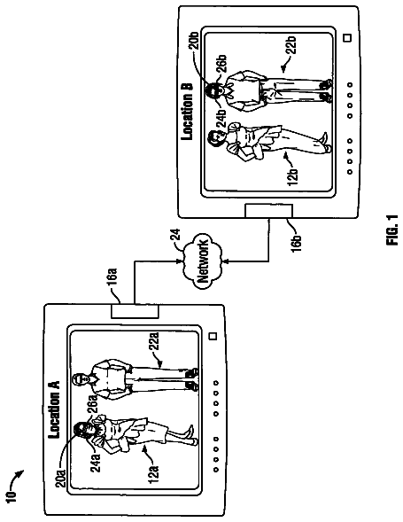
A virtual reality encounter system includes motion sensors positioned on a human user.
US 8,601,900 B2 · Assignee: Hong Fu Jin Precision Industry (ShenZhen) Co., Ltd. · Inventors: Wang; Hua-Shuai et al.
Sheet 1 of 4 from the published document. All sheets in the USPTO PDF
A support mechanism for a robot includes a support member, and a fixing member. The fixing member is placed on the support member, and includes a V-shaped resilient clip with a fixing groove. A robot securely configured with the support mechanism is also provided when the robot is being transported or stowed when not in service.
A robot needs to be stably placed on a transport or an appointed location, when it is being transported or not in service. However, the center of gravity of the robot is usually far away from the center of gravity of the robot base, so it is difficult to stably secure the robot in an upright position, and if the robot is placed on its side, surfaces of the robot may be damaged. Therefore, there is room for improvement within the art.
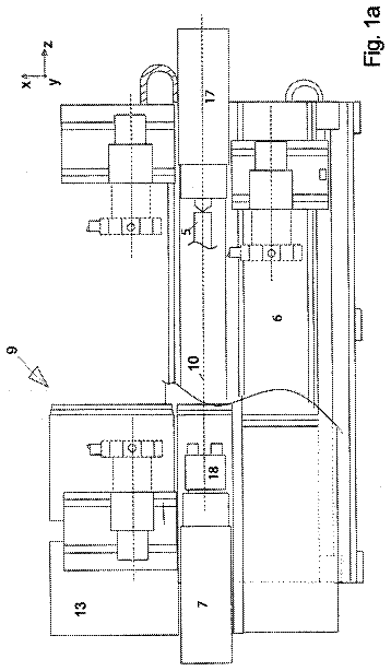
All 4 drawing sheets from the published document, cropped to the drawing.
What the patent claimed, word for word. All of it is now free to use.
The present disclosure relates to robots, particularly to a robot with a support mechanism.
A robot needs to be stably placed on a transport or an appointed location, when it is being transported or not in service. However, the center of gravity of the robot is usually far away from the center of gravity of the robot base, so it is difficult to stably secure the robot in an upright position, and if the robot is placed on its side, surfaces of the robot may be damaged.
Therefore, there is room for improvement within the art.
The components in the drawings are not necessarily drawn to scale, the emphasis instead placed upon clearly illustrating the principles of the present disclosure. Moreover, in the drawings, like reference numerals designate corresponding parts throughout the several views.
FIG. 1 is a partial, exploded, isometric view of an embodiment of a robot.
FIG. 2 is similar to FIG. 1, but viewed from another aspect.
FIG. 3 is an assembled, isometric view of the robot of FIG. 1.
FIG. 4 is a partial, cross-section view of FIG. 3, taken along the line IV-IV.
Referring to FIG. 1, one embodiment of a robot 100 includes a fixed base 10, a turning base 20, a first segment 30, a second segment 40, and a support mechanism 50. The fixed base 10 is used for mounting the robot 100 on the floor or other support means. The turning base 20 is rotatably fixed on the fixed base 10.
Referring to also to FIG. 2, the first segment 30 includes a first connecting end 31, a second connecting end 33, and a connecting portion 35. The connecting portion 35 interconnects the first connecting end 31 and the second connecting end 33. The first connecting end 31 is rotatably coupled to the turning base 20. An end of the second segment 40 is rotatably coupled to the second connecting end 33 of the first segment 30. An operating device (not shown), such as a clamp, a cutter or a detector, is generally positioned on the second segment 40 to realize various operations. The second segment 40 is substantially perpendicular to the first segment 30, so that the center of gravity of the robot 100 is away from that of the fixed base 10. The support mechanism 50 is detachably fixed to and supporting the first segment 30.
The connecting portion 35 includes a main body 351 and a plurality of ribs 353. In this embodiment, the main body 351 is cuboid. A receiving space 355 is defined in the main body 351 and faces the fixed base 10. The ribs 353 are fixed in the receiving space 355, and connect to the sidewalls of the main body 351 for reinforcement.
Referring to FIGS. 1, 3 and 4, the support mechanism 50 includes a support member 51 and a fixing member 53. The support member 51 includes a base 511, two support legs 512, and two stop portions 513. The two support legs 512 extend from opposite edges of the base 511, respectively. Each support leg 512 includes a main body 5121 and a bent portion 5123. One end of the main body 5121 is connected to one end of the base 511. An opening 5125 is defined in the center of the main body 5121, for facilitating handling of the support mechanism 50. The bent portion 5123 extends from one end of the main body 5121 away from the base 511, to contact the floor or other support means. An angle formed between the main body 5121 and the base 511 is greater than 90 degrees. The two stop portions 513 extend from opposite edges of the base 511 away from the support legs 512, respectively, for preventing the first segment 30 from coming apart when joined with the support mechanism 50. In this embodiment, the fixing member 53 is placed on the base 511 away from the support legs, and includes a generally V-shaped resilient clip 531 with a fixing groove 533.
When it is being transported or stowed when not in service, the robot 100 is placed on the transport or on floor for example, the first segment 30 is fixed to the support mechanism 50, and one rib 353 is fixed in the fixing groove 533 of the resilient clip 531. When the robot 100 is needed for performing a task or operation, the support mechanism 50 can be detached from the first segment 30.
Because the fixing member 53 employs a V-shaped resilient clip structure, the first segment 30 can be easily fixed in the fixing groove 533 of the resilient clip 531, and the support mechanism 50 cannot be easily detached from the robot 100, and the robot 100 can be more stably supported. The support mechanism 50 has a simpler structure and lower cost, and does not make the robot 100 more expensive.
It is believed that the present embodiments and their advantages will be understood from the foregoing description, and it will be apparent that various changes may be made thereto without departing from the spirit and scope of the embodiments or sacrificing all of its material advantages, the examples hereinbefore descried merely being preferred or exemplary embodiments.
About 891 words. The USPTO PDF has it with every drawing.
Fees are due 3.5, 7.5 and 11.5 years after grant. This patent expired on December 10, 2025, so the fee marked "not paid" was the one that went unpaid.
SUPPORT MECHANISM AND ROBOT WITH THE SAME
Filed May 2011 · published Jun 2012Support mechanism and robot with the same
Filed May 2011 · granted Dec 2013Earlier publications, parents and continuations. None of them can still be enforced, or this patent would not be listed.
Prior art cited by the examiner or applicant. Useful when you check your own idea for novelty.
Everything on this page comes from the documents linked above.