 Lapsed, fee not paid7 drawings
Energy & Sustainability · US 8,600,600 B2
System for driving spherical wheel
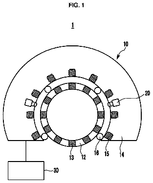
Disclosed is a system for driving a spherical wheel that includes a rotating sphere having a plurality of magnetic modules and a fixed body.
US 8,601,671 B2 · Assignee: Mitsubishi Denki Kabushiki Kaisha · Inventors: Toide; Yukari et al.
Sheet 1 of 11 from the published document. All sheets in the USPTO PDF
In a combination of, for example, a rotor having eight magnetic poles and a stator having twelve slots and pulsating components of permeance, which generate a sinusoidal cogging torque having maxima of the same number as the number of poles of the rotor, pressurizing parts arranged in predetermined positions, applying a force at an outer periphery of the stator and directed inwardly cancels the pulsating components of the cogging torque.
Cogging torque in an inner rotor type permanent-magnet type synchronous motor comprises pulsating components in torque, which is generated between teeth of a stator core (stator iron core) and a magnet rotor (rotor) when the magnet rotor is rotated by an external drive at the time of non-current-carrying to a winding, and only an order of a least common multiple of the number 2p of magnetic poles of a rotor magnet and the number Z of teeth (slots) of a stator core appears theoretically (see Non-Patent Document 1). However, this theory is limited to the case where rotors (mainly, magnets) and stator cores are uniform in shape and material properties and manufactured completely symmetrically with respect to the number of poles and the number of slots. Since the number of poles and the number of slots get out of symmetric property in real machines, in particular, in a field of volume produc
1 of 11 drawing sheets so far from the published document, cropped to the drawing. Every sheet is in the USPTO PDF.
What the patent claimed, word for word. All of it is now free to use.
The present invention relates to a permanent-magnet type synchronous motor contributory to reduction in cogging torque, and a method of manufacturing the same.
Cogging torque in an inner rotor type permanent-magnet type synchronous motor comprises pulsating components in torque, which is generated between teeth of a stator core (stator iron core) and a magnet rotor (rotor) when the magnet rotor is rotated by an external drive at the time of non-current-carrying to a winding, and only an order of a least common multiple of the number 2p of magnetic poles of a rotor magnet and the number Z of teeth (slots) of a stator core appears theoretically (see Non-Patent Document 1). However, this theory is limited to the case where rotors (mainly, magnets) and stator cores are uniform in shape and material properties and manufactured completely symmetrically with respect to the number of poles and the number of slots.
Since the number of poles and the number of slots get out of symmetric property in real machines, in particular, in a field of volume production, however, components of cogging torque having lower orders than the order of the least common multiple appear in many cases at large amplitudes. An increase in cogging torque has a great influence upon performance of products because of causing degradation in positioning accuracy for servomotors and degradation in feeling of steering for motors for automotive power steering.
Returning to the principle of torque generation, an explanation will be given to a mechanism for generation of pulsating components in torque. Torque is related to magnetic flux density and increases in the case where magnetic flux is easy to pass. Easiness, with which magnetic flux passes, is called permeance (reciprocal of magnetic resistance), and torque is generated in proportion to the square thereof. Accordingly, when permeance is varied, cogging torque is generated. In the case where a magnet making a source of generation of magnetic flux involves a nonuniform distribution and a symmetric property inconsistent with the number of poles, these are sensed on a side of a stator and pulsation having orders consistent with the number of slots and higher order components thereof appears. Higher order components are composed of higher harmonic wave components, which nonuniform components do not necessarily make a near-sinusoidal wave change to thereby cause.
Since main magnetic flux passes through an air from a magnet to return to the magnet through a back yoke portion from teeth of a stator core, materials of passages are divided into two. One is an air which is present between a rotor and a stator, and the other is a magnetic body that makes a core (iron core). In recent years, a laminate of flat rolled magnetic steel sheets and strip is in many cases used for such magnetic body, the magnetic property of flat rolled magnetic steel sheets and strip causes a problem frequently. In the case where flow of main magnetic flux involves a nonuniform distribution and a symmetric property inconsistent with the number of slots, these are sensed on a side of a rotor and pulsation having orders consistent with the number of poles and higher order components thereof appears.
For passages of magnetic flux, magnetic permeability .mu. indicative of easiness, with which magnetic flux passes, is constant in an air, so that a quantity of magnetic flux in the air appears due to a change in length of gaps (air gaps). Physical quantities having an influence on main magnetic flux moving through a rotor magnet and stator teeth are roughly classified into two, one of which is a gap (called an air gap) indicative of a shortest distance between an outside diameter of the rotor magnet and the stator teeth, and the other of which is a gap (generally called an open width) between the adjacent stator teeth. While an air gap is determined by an outside diameter shape of a rotor and an inside diameter shape of a stator, the inside diameter shape of a stator causes a problem in many cases.
Also, in the case where in order to facilitate a winding process, a method, in which a core is partially or wholly divided between teeth, is employed instead of manufacturing a stator core from a substantially circular-shaped unitary core, minute clearances are present to make clearance gaps when the divided portions are joined together.
Also, in the case where a core is partially divided and joined after winding, for convenience of a joint process, such part is in some cases made different in structure from the remaining part whereby non-uniformity in structure is generated.
Subsequently, cores manufactured from a magnetic body such as flat rolled magnetic steel sheets and strip generate, in many cases, individual differences in magnetic permeability due to various factors and a nonuniform distribution in the same individual one. One of the factors for generation of individual differences is a composition (grade) of flat rolled magnetic steel sheets and strip being a core material. Also, one of the factors for generation of differences in the same individual one is due to those different magnetic permeabilities in specific portions of a core obtained by a method of punching a core shape, which are caused by a difference (called magnetic anisotropy) in magnetic property between a direction of rolling of, for example, flat rolled magnetic steel sheets and strip and a direction perpendicular thereto. Also, when flat rolled magnetic steel sheets and strip are punched by blades of a metallic die, forces exerted by the blades cause degradation of teeth end surfaces in magnetic permeability, and the process of fitting of concave and convex portions (called caulking) for fixation of a laminate causes degradation of a caulked portion and its neighborhood.
Further, the manufacturing process of mounting a frame on an outer periphery of a stator core to fix the same to a bracket that supports a bearing is in many cases performed in order to prevent a stator from being displaced by torque generated between a rotating rotor and the stator, but a force exerted on the outer periphery of the stator core by the frame has an influence on not only a neighborhood of the outer periphery of the stator core, through which magnetic flux does not pass so much, but also a neighborhood of teeth, which makes a main passage, to cause degradation of flat rolled magnetic steel sheets and strip, which makes a main passage of magnetic flux, in magnetic property and displacement of teeth, thus changing an inside diameter shape of the stator core.
Unless gaps and magnetic property are ideally uniformly formed for the number of poles and the number of slots, cogging torque of lower orders is generated.
As described above, cogging torque of orders consistent with the number Z of slots is generated due to non-uniformity on a side of a magnet, and cogging torque of orders consistent with the number 2p of poles is generated due to various factors, such as non-uniformity in air gap, non-uniformity in open width, non-uniformity in clearance gap, distribution of magnetic property with respect to magnetic anisotropy of flat rolled magnetic steel sheets and strip, distribution of magnetic property generated by partial degradation of magnetic permeability due to punching, caulking, and stress in a frame, nonuniform distribution of clearance gaps of a split core, structural non-uniformity of joints, etc.
These factors are inevitably generated in actual motors by a manufacturing method for enhancement in volume production, or a limit in working accuracy in manufacturing processes.
Trials for reduction in cogging torque have been made taking notice of such manufacturing processes. For example, in order to obtain uniformity in air gaps, JP-A-2001-218429 (see Patent Document 1) proposes measures of ensuring roundness of inside diameter by uniformly applying pressure over outer and inner peripheries of a core to fix the same when a stator is to be press fitted into a frame. In JP-A-09-23687 (see Patent Document 2), it is tried to reduce cogging torque due to magnetic anisotropy by displacing a direction of magnetic anisotropy from central angles of teeth.
Also, in JP-A-2001-95199 (see Patent Document 3), it is tried to prevent an increase in cogging torque by maintaining a frame as uniform as possible in thickness to maintain a force given to a stator by the frame uniformly and to prevent the stator from being nonuniformly changed in inside diameter shape. In JP-A-2001-258225 (see Patent Document 4) and JP-A-2002-272074 (see Patent Document 5), measures for restriction on the number of caulked portions have been proposed taking account of influences by caulking. Further, in JP-A-06-52346 (see Patent Document 6), lamination is made so as to arrange seams circumferentially at substantially equal intervals whereby it is tried to dissolve non-uniformity in magnetic flux, which is caused by the seams.
The inventors of the present application have researched components having the same orders as the number 2p of poles, among cogging torque having a smaller number of pulsation than a least common multiple of the number 2p of poles of a magnet and the number Z of slots of a stator and clarified that products manufactured in volume production appear in many cases as a result of superposition of cogging torque waveforms including an amplitude and a phase, of at least two or more factors. Accordingly, a fundamental understanding is obtained, in which measures taking notice of only one property as in the prior art are insufficient to enable adequately reducing cogging torque and measures for individual properties, for example, trying to make roundness approach zero cannot materialize a complete ideal state actually. In particular, for actual motors manufactured in volume production, it is difficult to unlimitedly make cogging torque approach zero without taking account of working accuracy. That is, a technique is demanded, in which cogging torque caused by working accuracy is grasped as net and cogging torque measured in a final stage of the manufacturing process is cancelled to be made zero. Non-Patent Document 1: Daikoku, et. al, "Cogging Torque Examination in Permanent Magnet Motors with Stressed Stator Core," Materials of workshop of rotating machinery of Electric Appliance Society RM-03-152, pp. 14-18 (November 2003) Patent Document 1: JP-A-2001-218429 Patent Document 2: JP-A-09-23687 Patent Document 3: JP-A-2001-95199 Patent Document 4: JP-A-2001-258225 Patent Document 5: JP-A-2002-272074 Patent Document 6:
In permanent-magnet type synchronous motors, cogging torque having the same orders as the number 2p of poles of a magnet is generated due to composite superposition of various factors, such as non-uniformity in air gap, non-uniformity in open width, non-uniformity in clearance gap, distribution of magnetic property with respect to magnetic anisotropy of flat rolled magnetic steel sheets and strip, distribution of magnetic property generated by partial degradation of magnetic permeability due to punching, caulking, and stress in a frame, nonuniform distribution of clearance gaps of a split core, structural non-uniformity of joints, etc. In this case, it is necessary to take notice of superposition of cogging torque waveforms including not only amplitudes but also phases, and it is necessary to take canceling measures to make cogging torque, which appears as a result of superposition, approach zero as consequence, in addition to taking compensating measures to separate and correctly estimate respective factors, in which amplitudes negate other properties and is apparently decreased, and to reduce individual amplitudes.
The invention has been thought of in order to solve the problems described above, and has its object to provide a permanent-magnet type synchronous motor, in which cogging torque having pulsating components of the same orders as the number 2p of poles of a magnet is decreased near to zero unlimitedly by separating composite individual factors of cogging torque and taking thorough measures of reducing the cause of large amplitudes in an experimental manufacturing stage, and regulating processes to superpose properties, in which phase control is possible, on properties, in which amplitudes cannot be decreased for the convenience of manufacture, to cancel the latter, and a method of manufacturing the same.
The invention comprises a stator having Z (Z is a natural number) slots, on which a coil is arranged, a rotor having permanent magnets of 2p (p is a natural number) poles and inserted into a torus of the stator, and a frame that pressurizes an outer periphery of the stator inward in N locations (N is a natural number) with larger forces than those for other portions. Specifically, in case of shrinkage fit and a molding process, a frame, an external form of which is not a torus but has is substantially square to have a thickness distribution, may be made use of, and in the case where the frame is substantially a torus in shape, pressurizing parts such as spacer, etc. are partially added to make pressurized regions N in number. In the case where the frame is not substantially circular in outer shape and pressurized points are smaller in number than N, pressurizing parts are added to increase pressurized points in number. In case of using pressurization or pressurizing parts, a mechanism is made capable of adjusting pressurized regions and a degree of pressurization.
In processes until mounting of the frame, marking affording discrimination of individual teeth or slots of the stator is made in one or more locations and made a reference position. In the case where a split core is adopted to include seams as joined, the seams can be made a reference position. In a stage of trial manufacture, with respect to cogging torque having components of the same orders as the number 2p of poles and caused by the stator, a state of generation is separated by characteristics and grasped in a manufacturing process before mounting of the frame by measuring cogging torque of a stator without a frame, or measuring cogging torque of a stator, on which a torus having a high accuracy in shape and subjected to influences of stress by the frame as small as possible is experimentally mounted.
In a process of mounting the frame on the stator, a feature resides in that fixation is made after the positional relationship between the reference position of the stator and pressurizing regions in N locations on the frame is determined in terms of N number and an angle, which cancel the state of cogging torque before mounting of the frame. Angles between the reference position and pressurized points are determined on the basis of data, in which cogging torque generated in a manufacturing process before mounting of the frame and the cause for generation of the cogging torque are separated by characteristics.
According to the invention, it is possible to obtain a permanent-magnet type synchronous motor, in which cogging torque attributable to non-uniformity of a stator is cancelled to decrease an entire cogging torque, by giving to predetermined locations on the stator non-uniformity of magnetic property caused by stress, air gap on an inside diameter caused by stress, open width, and displacement of clearance gap.
FIG. 1 is a view showing a cross section of a permanent-magnet type synchronous motor perpendicular to an axial direction of a stator, according to an embodiment 1 of the invention.
FIG. 2 is a view showing a cross section of a permanent-magnet type synchronous motor perpendicular to an axial direction of a stator, according to an embodiment 2 of the invention.
FIG. 3 is a view showing a cross section of a permanent-magnet type synchronous motor perpendicular to an axial direction of a stator, according to an embodiment 3 of the invention.
FIG. 4 is a view showing a cross section of a permanent-magnet type synchronous motor perpendicular to an axial direction of a stator, according to an embodiment 4 of the invention.
FIG. 5 shows a thickness distribution of a frame, in a normal direction, in the embodiment 4 of the invention.
FIG. 6 is a view illustrating an articulation type iron core in the embodiment 5 of the invention.
FIG. 7 is a view illustrating butt portions of the articulation type iron core in the embodiment 5 of the invention.
FIG. 8 shows results of actual measurement of lower-order components of cogging torque in the case where positioning is made in the butt portions of the articulation type iron core in the embodiment 5 of the invention and manufacture is carried out.
FIG. 9 is a view showing a cross section of a permanent-magnet type synchronous motor perpendicular to an axial direction of a stator, according to an embodiment 6 of the invention.
FIG. 10 shows an example of results of measurement of cogging torque at an angle of a rotor in the permanent-magnet type synchronous motor according to the embodiment 6 of the invention.
FIG. 11 is a view showing a cross section perpendicular to an axial direction of a permanent-magnet type synchronous motor according to an embodiment 7 of the invention.
FIG. 12 shows an example of results of measurement of cogging torque at an angle of a rotor in the permanent-magnet type synchronous motor according to the embodiment 7 of the invention.
FIG. 13 is a view showing a cross section perpendicular to an axial direction of a permanent-magnet type synchronous motor according to an embodiment 8 of the invention.
FIG. 14 is a transverse, cross sectional view showing a permanent-magnet type synchronous motor according to the embodiment 8 of the invention.
FIG. 15 is a view showing a cross section perpendicular to an axial direction of a permanent-magnet type synchronous motor according to an embodiment 10 of the invention.
Embodiment 1
FIG. 1 is a view illustrating a method of assembling a motor in the embodiment 1 to carry out the invention. In FIG. 1, a stator iron core (stator core) 1 is constituted by laminating flat rolled magnetic steel sheets and strip, in which twelve teeth 2 and twelve slots 3 are formed. A frame 4 (referred below to as circular frame) is predetermined to be circular as a cross sectional shape of a frame 4 perpendicular to a rotor rotating shaft (not shown) in this example. Screw holes 5 for assembly of a rotor and a stator are provided to be opposed to each other at an angle of 180 degrees. Since the frame 4 is machined conforming a die, it is substantially equivalent in form accuracy to the die, and a shape of that hole of the frame 4, which accommodates therein the stator iron core 1, is not so high in roundness (a difference of maximum/minimum dimensions of an inside diameter), the shape being an elliptical shape of, for example, about 120 .mu.m for products of a certain series.
FIG. 1 shows a straight line 6 indicative of a minor axis of the elliptical shape. Also, an outside diameter shape of the frame 4 is substantially similar to an inside diameter shape, and has an elliptical shape. Accordingly, the frame 4 is substantially constant in thickness in a circumferential direction and it is found that as a result of shape measurement that the screw holes 5 for mount are surely located in a direction of major axis of the ellipse. Accordingly, the thickness of the frame on the major axis is decreased by a magnitude amounting to a diameter of the screw holes.
On the other hand, the stator iron core 1 is generally fabricated by laminating cut portions of flat rolled magnetic steel sheets and strip while caulking them, and an outside diameter of the stator iron core 1 has a roundness of, for example, 50 .mu.m or less and is in many cases said to be substantially circular as compared with the shape of the hole of the frame 4.
Conventionally, when the stator iron core 1 is to be inserted into and fixed to the hole of the frame 4, the positional relationship of the frame 4 and the stator iron core 1 in a direction of rotation about a rotor rotational axis is not taken account of, but the stator iron core 1 is fixed to the frame 4 in an optional position by means of methods such as shrinkage fit, press fit, molding, etc.
Paying attention to the fact that the hole of the frame 4 is in many cases inferior in roundness to an external form of the stator iron core 1 as described above, the invention takes notice of usefulness in controlling the positional relationship in the direction of rotation in a fixing process, in which the frame 4 and the stator iron core 1 are fixed together in the manufacturing process.
For example, in the case where a stator iron core is fixed to a frame by means of shrinkage fit, the stator iron core in a normal temperature state is conformed to the frame, which is expanded in shape, and left at normal temperature, and in the meantime the frame is contracted in shape to clamp the stator iron core, at which stress is applied to a maximum-diameter side of the stator iron core by the frame. That is, for the frame 4, of which a hole has an elliptical-shaped cross section, and the stator iron core 1 having a substantially circular-shaped cross section, the frame 4 and the stator iron core 1 contact with each other in a direction along the minor axis of the elliptical shape in an initial stage of the fixing process.
Further, it can be generally said that the larger the thickness of the frame, the larger the shape deformation at the time of expansion and shrinkage, and the larger the thickness of the frame, the larger a force applied directly on an outermost diameter portion of a side of the stator iron core by the frame. Accordingly, in fixation in such case, a location, in which stress of the stator iron core 1 becomes extreme (maximum in this case), corresponds to a location, in which the straight line 6 consistent with the minor axis intersects an outside diameter of the stator iron core 1. In the embodiment, the location, in which stress of the stator iron core 1 becomes extreme, is made nearest to the teeth 2 of the stator iron core 1. Here, since the teeth 2 is even in number, in order to realize the arrangement, it suffices that the straight line 6 corresponding with the minor axis be caused to be consistent with a teeth center line 7, which connects between the teeth 2 positioned at opposite poles of the stator iron core 1, or made nearest thereto.
While teeth center lines 7 corresponding in number to a half of the total number of teeth, that is, a plurality of teeth center lines can be set, the teeth center line 7 being positionally registered with the straight line 6 may be any one of the plurality of teeth center lines 7. After positioning in this manner, the both elements are fixed while the mutual positional relationship is maintained. Taking as an example fixation with shrinkage fit, the hole of the frame 4 and the external form of the stator iron core 1 are first measured along with the shapes thereof at an environmental temperature T0. Normally, measurement every frame and every stator iron core is not necessary provided that typical samples are measured.
Subsequently, the frame 4 is raised in temperature up to a specific temperature T1. T1 can be beforehand found through computational estimation as a temperature until the hole of the frame 4 is increased in diameter by thermal expansion to afford insertion of the stator iron core 1 into the hole provided that a material and a shape for the stator iron core 1 are given.
In this manner, the stator iron core 1 is inserted into the frame 4, which has been heated to temperature T1. Then the stator iron core 1 is rotated or the like to be positioned relative to the frame 4 so that the straight line 6 corresponding to the minor axis of the hole of the frame 4, which has been found, is made consistent with the teeth center line 7 of the stator iron core 1. After positioning in this manner, the frame 4 is cooled to normal temperature T0 to allow the stator iron core 1 to be fixed to the frame 4 through shrinkage at the time of cooling.
As described above, the straight line 6 corresponding to the minor axis of the frame 4 and the teeth center line 7 of the stator iron core 1 are positioned and fixed together whereby cogging torque is decreased as compared with the case where fixation is made in other locations. It is thought that the cause for this is that since the stator iron core 1 is larger in thickness by the teeth 2 than that in other locations to be large in mechanical strength, a region having an influence on a passage, through which magnetic flux passes inside the stator iron core 1, is small and hard to be influenced by stress when magnetic flux passes.
With a permanent-magnet type motor, assuming that a rotor and a stator, which include a magnet, take theoretical values, those times, in which cogging torque pulsates when a rotor makes a round, become those corresponding to a least common multiple of the number of poles of a magnet and the number of slots of a stator as shown on pages 2 to 4 of the Non-Patent Document 1. In actual products, however, there is occurred the number of pulsation smaller than a least common multiple of the number of poles of a magnet and the number of slots of a stator, which is typical in pulsating components being the same in number as the number of slots of a stator, and integral times thereof, or as the number of poles of a magnet and integral times thereof.
Among these, the formula
on page 4 of the Non-Patent Document 1 shows that one of occurrence conditions for pulsating components of cogging torque, which are the same in number as the number of poles of a magnet, is the case where the permeance distribution function formed by a stator has those pulsating components of N times every revolution of a rotor, which has a predetermined condition, and further shows the N predetermined conditions. That is, pulsating components of permeance formed by a stator side constitute one of causes for generation of pulsating components of cogging torque, which are the same in number as the number of poles of a magnet. In case of 8 poles and 12 slots, N=4 is in the stator iron core and N=4 as higher-order components created by N=2 also makes a cause for lower-order pulsating components.
Mechanism for occurrence of influences on cogging torque as a result of application of a force on a stator iron core from a frame at the time of fixation of the frame are roughly classified into two. One of them is a problem with deformation of an iron core. That is, when a force propagates inside the iron core, it is problematic how positions of teeth tip ends and open widths (these have an influence on air gaps for passage of magnetic flux) are varied as compared with those before being fixed to the frame and what nonuniform distribution they have as seen every tooth when the frame and the iron core balance in a final state with respect to stiffness (hardness or the like).
The second one of them is that energy, which cannot be finally deformed and is left as residual stress inside the iron core, partially changes the magnetic property (easiness, with which magnetic flux passes, magnetic permeability) of the iron core, and consequently how a manner, in which magnetic flux passes, is changed and what nonuniform distribution is generated.
For these changes, structural analysis enables computing of a state of final deformation and a state, in which residual stress is distributed. In particular, the distribution of residual stress makes a cue to know how a passage, through which magnetic flux passes, is varied, and in what region such change comes out, as seen every tooth.
As an example, structural analysis was made in the case where a completely circular stator iron core was shrinkage fitted into a frame, which is circular in inside diameter and elliptical in outside diameter, with the result that residual stress became larger in amplitude of double-symmetrical pulsation with the case where a maximum point of stress was made consistent with a slot center, than with the case where a maximum point of stress was made consistent with a teeth center. It is thought that since residual stress changes the magnetic property of flat rolled magnetic steel sheets and strip, the magnetic property of flat rolled magnetic steel sheets and strip also becomes in amplitude of double-symmetrical pulsation and cogging torque having lower-order pulsating components is increased. That is, in order to decrease cogging torque having lower-order pulsating components, it is thought that making a maximum point of stress consistent with a teeth center is more effective than making a maximum point of stress consistent with a slot center.
However, instead of positioning the maximum point of stress nearest to the teeth 2, it is also in some cases effective to position the point nearest to a center of the slot 3. That is, a slot center line 8 connecting between centers of slots 3 positioned at opposite poles is made consistent with the straight line 6. The effect of decreasing cogging torque is recognized in this case except the case where positioning is made on the basis of the teeth center line 7. Since in this position, the stator iron core 1 is smaller in thickness than in other locations but an improvement in cogging torque is recognized, that direction, in which stress is applied, is not radial on the circular-shaped cross section of the stator iron core 1 but angular relative to the radial direction, and residual stress itself is dispersed to become small in amplitude, which appears to be effective in decreasing cogging torque, as shown in the structural analysis.
This is because cogging torque finally appears not only as a change in magnetic property caused by the residual stress but also as a result of a combination of this change with flows of magnetic flux when an actual motor operation is performed, and it is thought that with which of a teeth center and a slot center the maximum point of stress should be optimally made consistent is changed according to conditions such as a detailed shape of a stator iron core, direction of magnetization of a permanent magnet on a rotor side, magnitude of magnetic flux, etc., so that it is desirable to make use of structural analysis to determine an optimum position as shown in an embodiment 2.
Also, since it is thought that also in the case where a combination of the number of poles and the number of slots is different from that in the present embodiment, pulsating components appearing in cogging torque change depending upon whether stress applied on a stator iron core from a frame is applied on a side of a slot of the stator iron core or a side of teeth, it is necessary to make constant a manner, in which stress is applied on the stator iron core from the frame, in order to suppress dispersion in cogging torque. Therefore, it is necessary to take notice of a point, at which stress applied on the stator iron core from the frame is maximum or minimum, to position a teeth center and a slot center of the stator iron core relative to the point.
In this manner, cogging torque in the both cases is decreased as compared with the case where fixation is made in other positions, and further provided that the frame 4 and the stator iron core 1 are fixed together in a controlled state, in which the constant positional relationship is maintained in this manner, cogging torque is made uniform in magnitude as far as the same type of device is associated. Since a method of controlling such mutual fixed positional relationship constant is not conventionally adopted, cogging torque in conventional products involves a large dispersion in magnitude and an increase in an average statistical center value of the cogging torque and products are reduced in yield in the case where magnitude of cogging torque is made an index of product control. According to the invention, dispersion in magnitude of cogging torque is improved and products are enhanced in yield conjointly with the effect of reduction in cogging torque.
Such effect is obtained only by simple positioning and fixation and does not need that complex manufacturing process, in which fins disclosed in Patent Document 3 is manufactured, so that it can simplify the manufacturing process to be also effective in reduction in cost. Also, according to the invention disclosed in Patent Document 3, a frame is much reduced in effective thickness and involves a fear in mechanical strength, but the present invention involves less reduction in effective thickness and is excellent in this respect.
Embodiment 2
FIG. 2 shows a method of assembling a motor in the embodiment 2 of the invention, and the same circular frame as that in the embodiment 1 is taken as an example in the figure. The reference numerals are the same as those in FIG. 1.
In the embodiment 2, there is illustrated the case where a position of a maximum point of stress applied on a stator iron core 1 from a frame 4 is not clear from shapes thereof. Stated taking, for example, shrinkage fit as an example, a hole of the frame 4 and an external form of the stator iron core 1 are both elliptical, and it is not clear which location of the stator iron core 1 comes first into contact with the frame in the case where the frame 4 is cooled. Accordingly, the maximum point of stress is not clear.
In order to determine a position of a maximum point of stress in such case, it suffices to make use of, for example, a structural analysis program to determine a distribution of stress applied on the stator iron core 1 from the frame 4.
When shape and material of the frame 4, shape and material of the stator iron core 1, conditions of mutual arrangement, and conditions of temperature are input, the structural analysis program can be used to calculate a distribution of stress applied on the stator iron core in case of fixation through, for example, shrinkage fit. A predetermined arrangement can be determined by finding an arrangement, in which a maximum value of stress comes to a position corresponding a teeth center line 7 or a slot center line 8 on the basis of results of the calculation with respect to conditions (specifically, for example, an angle of rotation is changed) of plural arrangements of the frame 4 and the stator iron core 1.
In addition, since stress is applied on a side of the stator iron core from the frame to propagate inside while being accompanied by strain with the final result that distribution and direction of residual stress are found in this method, it is in some cases preferred from the viewpoint of reduction in cogging torque that a maximum value of stress preferably come to other position on the basis of such information instead of having the maximum value coming to a neighborhood of teeth, or a neighborhood of a slot. This leads to judgment on the basis of a direction of stress and a thickness of the stator iron core 1 in the direction.
In addition, when positioning is made in a position once determined for the type of device to fix the frame 4 and the stator iron core 1 together, there is produced an effect of reduction in dispersion in addition to the effect of reduction in cogging torque as described in the embodiment 1. Accordingly, as compared with a conventional method of manufacturing a motor, in which fixation is made without positioning in a fixed positional relationship, an improvement in dispersion of magnitude of cogging torque and the effect of reduction in cogging torque are combined to enhance products in yield.
The above matter is likewise established even when an external form of the frame 4 is rectangular or otherwise, and the same effect can be obtained.
Embodiment 3
FIG. 3 is a view illustrating a method of assembling a motor in the embodiment 3 of the invention. The same reference numerals as those in FIG. 1 denote the same parts. A frame 4 is a square one, a hole of the frame 4 is substantially circular in cross section perpendicular to a rotating shaft of a rotor, and an external form of a stator iron core 1 is also substantially circular.
In such case, since the thickness of the frame 4 has a clear distribution in a circumferential direction, stress applied on a side of the stator iron core 1 from the frame 4 is dependent upon the thickness of the frame 4, and it is thought that the larger the thickness of the frame in a normal direction, the larger the stress applied on the side. That is, stress applied on the stator iron core 1 from the frame 4 is increased in a diagonal direction, in which the thickness of the frame 4 is increased as compared with the other case.
Accordingly, the effect of reduction in cogging torque like the effect described in the embodiment 1 can be obtained by making positioning so as to make a teeth center line 7 of the stator iron core 1 consistent with either of two diagonal lines 9 of the frame 4 in order to set the teeth center line to a maximum point of stress, and fixing the stator iron core 1 to the frame 4. Also, in the case where the thickness of the frame has a clear distribution in the normal direction and stress dependent upon the thickness is applied to the stator iron core and in the case where the distribution is tetra-symmetrical relative to 360 degrees of a machine angle, the number of slots is 12, and the number of slots is divided by 4 being a symmetric property to result in 3 being odd, it is not necessarily necessary to take notice of only a point, at which stress becomes maximum, and even when taking notice of a point, at which stress becomes minimum, a slot center line of the stator iron core is made consistent with a side center line of the frame being a point, at which stress becomes minimum, it results that a teeth center is made consistent with a point, at which stress becomes maximum.
In this manner, it can be said that according to a shape of a frame and the number of slots it is unnecessary to take notice of only a point, at which stress becomes maximum, and it does not matter if a reference for positioning is determined taking notice of a point, at which stress becomes minimum. Details of the manufacturing method are the same as described in the embodiment 1 except the method of positioning.
In addition, while fixation of a frame and a stator iron core is made by means of shrinkage fit in the embodiments 1 to 3, such fixation may be made by means of press fit, or an adhesive, and the way of fixation is not particularly limitative.
Further, while the invention exemplifies a stator having 12 slots, the case with other pole slots will do, and there is no limitation thereon.
Besides, an external form of a frame having a circular-shaped or a square-shaped cross section is exemplified in the respective embodiments, a triangular or a pentagonal cross section will do, and there is no limitation in a shape of a frame.
Embodiment 4
FIG. 4 is a view illustrating a method of assembling a motor in the embodiment 4 of the invention. The same reference numerals as those in FIG. 1 denote the same parts. A frame 4 is a substantially square one, and includes substantially circular notches 4a in diagonal directions. Also, although being not shown, a connector box or the like is in some cases mounted above the frame to have an influence on a thickness of the frame 4.
In such case, since a thickness distribution of the frame 4 cannot be readily known, the angle dependence of frame thickness in a normal direction is found as shown in FIG. 5.
[As a result, it is found that a region, which is thick in thickness distribution and in which stress applied on the stator iron core 1 from the frame 4 becomes maximum, is steep and a region, which is minimum in thickness distribution and in which stress applied on the stator iron core becomes minimum, is gentle in change.
The description continues in the full USPTO document.
About 6,847 words. The USPTO PDF has it with every drawing.
Fees are due 3.5, 7.5 and 11.5 years after grant. This patent expired on December 10, 2025, so the fee marked "not paid" was the one that went unpaid.
Permanent-magnet type synchronization motor and method of manufacturing thereof
Filed Aug 2004 · published Mar 2006Permanent-magnet synchronous motor
Filed Aug 2004 · granted Dec 2008METHOD OF MANUFACTURING PERMANENT-MAGNET SYNCHRONOUS MOTOR
Filed Nov 2008 · published Mar 2009Method of manufacturing permanent-magnet synchronous motor
Filed Nov 2008 · granted Dec 2010METHOD OF MANUFACTURING PERMANENT-MAGNET SYNCHRONOUS MOTOR
Filed Nov 2010 · published Mar 2011METHOD OF MANUFACTURING PERMANENT-MAGNET SYNCHRONOUS MOTOR
Filed Aug 2012 · published Dec 2012Method of manufacturing permanent-magnet synchronous motor
Filed Aug 2012 · granted Dec 2013Earlier publications, parents and continuations. None of them can still be enforced, or this patent would not be listed.
Prior art cited by the examiner or applicant. Useful when you check your own idea for novelty.
Everything on this page comes from the documents linked above.