Cross-reference to related applications
This application is related to commonly-assigned applications having U.S. patent application Ser. Nos. 13/109,875, 13/109,878, 13/109,883, and 13/109,941, each of which applications was filed on May 17, 2011, and each of which is hereby incorporated by reference in its entirety.
Background
The disclosed embodiments relate generally to panoramic photography. More specifically, the disclosed embodiments relate to techniques for improving panoramic photography for handheld personal electronic devices with image sensors.
Panoramic photography may be defined generally as a photographic technique for capturing images with elongated fields of view. An image showing a field of view approximating, or greater than, that of the human eye, e.g., about 160.degree. wide by 75.degree. high, may be termed "panoramic," Thus, panoramic images generally have an aspect ratio of 2:1 or larger, meaning that the image being at least twice as wide as it is high (or, conversely, twice as high as it is wide, in the case of vertical panoramic images). In some embodiments, panoramic images may even cover fields of view of up to 360 degrees, i.e., a "full rotation" panoramic image.
Many of the challenges associated with taking visually appealing panoramic images are well documented and well-known in the art. These challenges include photographic problems such as: difficulty in determining appropriate exposure settings caused by differences in lighting conditions across the panoramic scene; blurring across the seams of images caused by motion of objects within the panoramic scene; and parallax problems, i.e., problems caused by the apparent displacement or difference in the apparent position of an object in the panoramic scene in consecutive captured images due to rotation of the camera about an axis other than its center of perspective (COP). The COP may be thought of as the point where the lines of sight viewed by the camera converge. The COP is also sometimes referred to as the "entrance pupil." Depending on the camera's lens design, the entrance pupil location on the optical axis of the camera may be behind, within, or even in front of the lens system. It usually requires some amount of pre-capture experimentation, as well as the use of a rotatable tripod arrangement with a camera sliding assembly to ensure that a camera is rotated about its COP during the capture of a panoramic scene. Obviously, this type of preparation and calculation is not desirable in the world of handheld, personal electronic devices and ad-hoc panoramic image capturing.
Other well-known challenges associated with taking visually appealing panoramic images include post-processing problems such as: properly aligning the various images used to construct the overall panoramic image; blending between the overlapping regions of various images used to construct the overall panoramic image; choosing an image projection correction (e.g., rectangular, cylindrical, Mercator) that does not distort photographically important parts of the panoramic photograph; and correcting for perspective changes between subsequently captured images.
Accordingly, there is a need for techniques to improve the capture and processing of panoramic photographs on handheld, personal electronic devices such as mobile phones, personal data assistants (PDAs), portable music players, digital cameras, as well as laptop and tablet computer systems. By accessing information returned from positional sensors embedded in or otherwise in communication with the handheld personal electronic device, for example, micro-electro-mechanical system (MEMS) accelerometers and gyrometers, more effective panoramic photography techniques, such as those described herein, may be employed to achieve visually appealing panoramic photography results in a way that is seamless and intuitive to the user.
Summary
The panoramic photography techniques disclosed herein are designed to handle a range of panoramic scenes as captured by handheld personal electronic devices. Generalized steps to carry out the panoramic photography techniques described herein include: 1.) acquiring image data from the electronic device's image sensor's image stream (this may come in the form of serially captured image frames as the user pans the device across the panoramic scene); 2.) performing "motion filtering" on the acquired image data (e.g., using information obtained from positional sensors for the handheld personal electronic device to inform the processing of the image data); 3.) performing image registration between adjacent captured images; 4.) performing geometric corrections on captured image data (e.g., due to perspective changes and/or camera rotation about a non-COP point); and 5.) "stitching" the captured images together to create the panoramic scene, i.e., blending the image data in the overlap area between adjacent captured images. Due to image projection corrections, perspective corrections, alignment, and the like, the resultant stitched panoramic image may have an irregular shape. Thus, the resultant stitched panoramic image may optionally be cropped to a rectangular shape before final storage if so desired. Each of these generalized steps will be described in greater detail below.
1. Image Acquisition
Some modern cameras' image sensors may capture image frames at the rate of 30 frames per second (fps), that is, one frame every approximately 0.03 seconds. At this high rate of image capture, and given the panning speed of the average panoramic photograph taken by a user, much of the image data captured by the image sensor is redundant, i.e., overlapping with image data in a subsequently or previously captured image frame. In fact, as will be described in further detail below, in some embodiments it may be advantageous to retain only a narrow "slit" or "slice" of each image frame after it has been captured. In some embodiments, the sift may comprise only the central 12.5% of the image frame. So long as there retains a sufficient amount of overlap between adjacent captured image slits, the panoramic photography techniques described herein are able to create a visually pleasing panoramic result, while operating with increased efficiency due to the large amounts of unnecessary and/or redundant data that may be discarded. Modern image sensors may capture both low dynamic range (LIAR) and high dynamic range (HDR) images, and the techniques described herein may be applied to each.
2. Motion Filtering
One of the problems currently faced during ad-hoc panoramic image generation on handheld personal electronic devices is keeping the amount of data that is actually being used in the generation of the panoramic image in line with what the device's processing capabilities are able to handle and the capacities of the device's internal data pathways. By using a heuristic of the camera motion based on previous frame registration, change in acceleration, and change of camera rotation information coming from the device's positional sensor(s), e.g., a gyrometer and/or accelerometer, it is possible to "filter out" image slits that would, due to lack of sufficient change in the camera's position, produce only redundant image data. This filtering is not computationally intensive and reduces the number of image slits that get passed on to the more computationally intensive parts of the panoramic image processing operation. Motion filtering also reduces the memory footprint of the panoramic image processing operation by retaining only the needed portions of the image data.
3. Image Registration
Image registration involves matching features in a set of images or using direct alignment methods to search for image alignments that minimize the sum of absolute differences between overlapping pixels. In the case of panoramic photography, image registration is generally applied between two consecutively captured or otherwise overlapping images. Various known techniques may be used to aid in image registration, such as feature detection and cross-correlation. By accessing information returned from a device's positional sensors, image registration techniques such as feature detection and cross-correlation may be improved and made more efficient. The positional information received from the device sensors may serve as a check against the search vectors calculated between various features or regions in the two images being registered. For instance, the movement of an object within a panoramic scene from one image frame to the next image that opposes the motion of the user's panning may suggest a local search vector that is opposed to the actual motion between the two images. By checking localized search vector information against information received from the device's positional sensors, inconsistent and/or unhelpful segments of the images may be discarded from the image registration calculation, thus making the calculation less computationally intensive and reducing the memory footprint of the panoramic image processing operation.
4. Geometric Correction
Perspective changes between subsequently captured image frames (or image slits) may result in the misalignment of objects located in overlapping areas between successive image frames (or slits). In the techniques described herein, information received from a device's positional sensors, e.g., a MEMS gyroscope, allows for the calculation of the rotational change of the camera from frame to frame. This data may then be used to employ a full perspective correction on the captured image frame. Performing a perspective or other geometric correction on the image data may be a crucial step before the alignment and stitching of successively captured image frames in some instances. Various known warping techniques, such as cubic interpolation or cubic splines (i.e., polynomial interpretation) may be used to correct the perspective and interpolate between successively captured image frames.
5. Image Stitching
The final step in assembling a panoramic image according to some embodiments is the "stitching" together of successively retained image frames. The image frames may be placed into an assembly buffer where the overlapping regions between the images (or portions of images) may be determined, and the image pixel data in the overlapping region may be blended into a final resultant image region according to a blending formula, e.g., a linear, polynomial, or other alpha blending formula. Blending between two successively retained image frames attempts to hide small differences between the frames but may also have the consequence of blurring the image in that area. This is not ideal for any object of interest occurring in the overlapping region, and is particularly undesirable for human faces occurring in the overlapping region, as they can become distorted by the blend, becoming very noticeable to a human observer of the panoramic image. By locating faces in the image frames being stitched, one embodiment of a panoramic photography process described herein avoids blending across a face by creating a scene graph so that the face gets used only from one of the image frames being blended. Due to the large number of overlapping image slits being captured, further refinements may also be employed to the selection of the image frame to use for the human face information, e.g., the presence of the face may be compared across successively retained image slits so that, e.g., a slit where the eyes of the face are open is selected rather than a slit where the eyes of the face are closed.
Thus, in one embodiment described herein, an image processing method is disclosed comprising: receiving a first sequence of images from an image sensor in a device; receiving rotational information for the device; selecting, based at least in part on the rotational information, a subset of the first sequence of images to generate a second sequence of images, combining a portion of each of the second sequence of images so that each portion of each image in the second sequence of images overlaps at least one other portion of one other image in the second sequence of images; and blending each of the overlaps between the portions of the images in the second sequence of images to produce a panoramic image.
In another embodiment described herein, an image processing method is disclosed comprising: performing image registration on a first image, wherein the first image is taken with the device at a first position; receiving data indicative of device movement from the first position to a second position; filtering out a second image from the plurality of images, based at least in part on a determination that the device movement has not exceeded a threshold amount of movement, wherein the second image is taken at the second position; performing image registration on one or more additional images from the plurality of images; and generating the panoramic image using the first image and the one or more additional images.
In yet another embodiment described herein, an image registration method is disclosed comprising: obtaining positional information from a device; obtaining first and second images from the device; aligning a plurality of regions in the first image with a corresponding plurality of regions in the second image to identify a plurality of corresponding regions; determining a search vector for each of the plurality of corresponding regions; selecting only those corresponding regions from the plurality of corresponding regions having a search vector consistent with the positional information to identify a plurality of consistent regions; and registering the first and second images using the plurality of consistent regions.
In still another embodiment described herein, an image registration method is disclosed comprising: receiving a first it mage captured by a device; receiving device movement data from one or more positional sensors; receiving a second image captured by the device; and performing image registration on the second image using the device movement data and the first image, wherein the device movement data provides a search vector used in the act of performing image registration, and wherein the second image is captured by the device at a later point in time than the first image.
In another embodiment described herein, an image processing method is disclosed comprising: obtaining a first image at a first time from a device; obtaining a second image at a second time from the device; receiving positional information from a sensor in the device, the positional information indicating an amount of change in the position of the device between the first and second times; applying a geometric correction to either the first or the second image based on the received positional information; and registering the first image with the second image.
In another embodiment described herein, an image processing method is disclosed comprising receiving image data for a plurality of image frames at a device; receiving sensor data indicative of device movement between the capture of a first one of the plurality of image frames and a second one of the plurality of image frames; and applying a perspective correction to either the first or the second ones of the plurality of image frames based on the received sensor data.
In yet another embodiment described herein, a method to generate panoramic images is disclosed comprising: obtaining a first image having a first region and a second region, the second region including a first representation of a face, the first image stored in a first memory; obtaining a second image having a third region and a fourth region, the third region including a second representation of the face, the second image stored in a second memory; aligning the first and second images so that the second and third regions overlap to generate an overlap region; masking an area corresponding to the first representation of the face in the overlap region to generate a mask region; blending the first and second images in the overlap region, except for the mask region, to generate a blended region; and generating a result image comprising the first region, the fourth region and the blended region wherein the area in the blended region corresponding to the mask region is replaced with the first representation of the face.
In still another embodiment described herein, a method to generate panoramic images is disclosed comprising: receiving data representative of a plurality of images comprising a scene at a device; determining an overlapping region between a first image and a second image from the plurality of images; identifying a feature of interest that is represented at a location in each of the first image and the second image, wherein each of the representations are located in the overlapping region; selecting the representation of the feature of interest from the first; blending between the first image and the second image in the overlapping region to generate a resulting overlapping region; and assembling the first image and the second image, using the resulting overlapping region to replace the overlapping region between the first image and the second image, wherein the act of blending excludes the location of the identified feature of interest, and wherein the selected representation is used in the resulting overlapping region at the location of the identified feature of interest.
In another embodiment described herein, a method to generate panoramic images is disclosed comprising: receiving at a device data representative of a plurality of images; identifying one or more locations in the plurality of images in which one or more faces are located; and blending overlapping regions of the plurality of images to form a panoramic image, wherein the act of blending excludes regions of an image having the one or more face locations in an overlapping region.
Positional sensor-assisted panoramic photography techniques for handheld personal electronic devices in accordance with the various embodiments described herein may be implemented directly by a device's hardware and/or software, thus making these robust panoramic photography techniques readily applicable to any number of electronic devices with appropriate positional sensors and processing capabilities, such as mobile phones, personal data assistants (PDAs), portable music players, digital cameras, as well as laptop and tablet computer systems.
Brief description of the drawings
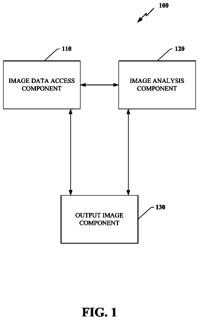
FIG. 1 illustrates a system for panoramic photography with the assistance of positional sensors, in accordance with one embodiment
FIG. 2 illustrates a process for creating panoramic images with the assistance of positional sensors, in accordance with one embodiment.
FIG. 3 illustrates an exemplary panoramic scene as captured by an electronic device, in accordance with one embodiment.
FIG. 4 illustrates a process for performing positional sensor-assisted motion filtering for panoramic photography, in accordance with one embodiment.
FIG. 5A illustrates an exemplary panoramic scene as captured by an electronic device panning across the scene with constant velocity, in accordance with one embodiment.
FIG. 5B illustrates an exemplary panoramic scene as captured by an electronic device panning across the scene with non-constant velocity, in accordance with one embodiment.
FIG. 6 illustrates image "slits" or "slices," in accordance with one embodiment.
FIG. 7A illustrates an exemplary panoramic sweep with arch, in accordance with one embodiment.
FIG. 7B illustrates an exemplary near-linear panoramic sweep, in accordance with one embodiment.
FIG. 7C illustrates an exemplary "short arm" panoramic sweep, in accordance with one embodiment.
FIG. 7D illustrates an exemplary "long arm" panoramic sweep, in accordance with one embodiment.
FIG. 8 illustrates a process for performing image registration for panoramic photography, in accordance with one embodiment.
FIG. 9 illustrates positional information-assisted feature detection, according to one embodiment.
FIG. 10 illustrates search vector segments for a given image frame, according to one embodiment.
FIG. 11 illustrates a decision flow chart for image registration, in accordance with one embodiment.
FIG. 12 illustrates a process for performing geometric correction for panoramic photography, in accordance with one embodiment.
FIG. 13 illustrates perspective change due to camera rotation in the context of image slits or slices, in accordance with one embodiment.
FIG. 14 illustrates a process for performing image stitching for panoramic photography, in accordance with one embodiment.
FIG. 15 illustrates an exemplary stitched image, according to a prior art technique.
FIG. 16 illustrates an exemplary blending error occurring in a stitched panoramic image assembled according to a prior art technique.
FIG. 17 illustrates exemplary regions of interest in a stitched panoramic image, in accordance with one embodiment.
FIG. 18 illustrates an exemplary scene graph for a region-of-interest-aware stitched panoramic image, in accordance with one embodiment.
FIG. 19 illustrates a simplified functional block diagram of a representative electronic device possessing a display.
Detailed description
This disclosure pertains to devices, methods, and computer readable media for performing positional sensor-assisted panoramic photography techniques in handheld personal electronic devices. Generalized steps may be used to carry out the panoramic photography techniques described herein, including: 1.) acquiring image data from the electronic device's image sensor; 2.) performing "motion filtering" on the acquired image data, e.g., using information obtained from positional sensors of the electronic device to inform the processing of the image data; 3.) performing image registration between adjacent captured images; 4.) performing geometric corrections on captured image data, e.g., due to perspective changes and/or camera rotation about a non-center of perspective (COP) camera point; and 5.) "stitching" the captured images together to create the panoramic scene, e.g., blending the image data in the overlap area between adjacent captured images. The resultant stitched panoramic image may be cropped before final storage if so desired.
The techniques disclosed herein are applicable to any number of electronic devices with optical sensors such as digital cameras, digital video cameras, mobile phones, personal data assistants (PDAs), portable music players, as well as laptop and tablet computer systems.
In the interest of clarity, not all features of an actual implementation are described. It will of course be appreciated that in the development of any actual implementation (as in any development project), numerous decisions must be made to achieve the developers' specific goals (e.g., compliance with system- and business-related constraints), and that these goals will vary from one implementation to another. It will be further appreciated that such development effort might be complex and time-consuming, but would nevertheless be a routine undertaking for those of ordinary skill having the benefit of this disclosure.
In the following description, for purposes of explanation, numerous specific details are set forth in order to provide a thorough understanding of the inventive concepts. As part of the description, some structures and devices may be shown in block diagram form in order to avoid obscuring the invention. Moreover, the language used in this disclosure has been principally selected for readability and instructional purposes, and may not have been selected to delineate or circumscribe the inventive subject matter, resort to the claims being necessary to determine such inventive subject matter. Reference in the specification to "one embodiment" or to "an embodiment" means that a particular feature, structure, or characteristic described in connection with the embodiment is included in at least one embodiment of the invention, and multiple references to "one embodiment" or "an embodiment" should not be understood as necessarily all referring to the same embodiment.
Referring now to FIG. 1, a system 100 for panoramic photography with the assistance of positional sensors is shown, in accordance with one embodiment. The system 100 as depicted in FIG. 1 is logically broken into four separate layers. Such layers are presented simply as a way to logically organize the functions of the panoramic photography system. In practice, the various layers could be within the same device or spread across multiple devices. Alternately, some layers may not be present at all in some embodiments.
First the Camera Layer 120 will be described. Camera layer 120 comprises a personal electronic device 122 possessing one or more image sensors capable of capturing a stream of image data 126, e.g., in the form of an image stream or video stream of individual image frames 128. In some embodiments, images may be captured by an image sensor of the device 122 at the rate of 30 fps. Device 122 may also comprise positional sensors 124. Positional sensors 124 may comprise, for example, a MEMS gyroscope, which allows for the calculation of the rotational change of the camera device from frame to frame, or a MEMS accelerometer, such as an ultra compact low-power three axes linear accelerometer. An accelerometer may include a sensing element and an integrated circuit (IC) interface able to provide the measured acceleration of the device through a serial interface. As shown in the image frames 128 in image stream 126, tree object 130 has been captured by device 122 as it panned across the panoramic scene. Solid arrows in FIG. 1 represent the movement of image data, whereas dashed line arrows represent the movement of metadata or other information descriptive of the actual image data.
Next, the Filter Layer 140 will be described. Filter layer 140 comprises a motion filter module 142 that may receive input 146 from the positional sensors 124 of device 122. Such information received from positional sensors 124 is used by motion filter module 142 to make a determination of which image frames 128 in image stream 126 will be used to construct the resultant panoramic scene. As may be seen by examining the exemplary motion filtered image stream 144, the motion filter is keeping only one of every roughly three images frames 128 captured by the image sensor of device 122. By eliminating redundant image data in an intelligent and efficient manner, e.g., driven by positional information received from device 122's positional sensors 124, motion filter module 142 may be able to filter out a sufficient amount of extraneous image data such that the Panoramic Processing Layer 160 receives image frames having ideal overlap and is, therefore, able to perform panoramic processing on high resolution and/or low resolution versions of the image data in real time, optionally displaying the panoramic image to a display screen of device 122 as it is being assembled in real time.
Panoramic Processing Layer 160, as mentioned above, possesses panoramic processing module 162 which receives as input the motion filtered image stream 144 from the Filter Layer 140. The panoramic processing module 162 may preferably reside at the level of an application running in the operating system of device 122. Panoramic processing module 162 may perform such tasks as image registration, geometric correction, alignment, and "stitching" or blending, each of which functions will be described in greater detail below. Finally, the panoramic processing module 162 may optionally crop the final panoramic image before sending it to Storage Layer 180 for permanent or temporary storage in storage unit 182. Storage unit 182 may comprise, for example, one or more different types of memory, for example, cache, ROM, and/or RAM. Panoramic processing module 162 may also feedback image registration information 164 to the motion filter module 142 to allow the motion filter module 142 to make more accurate decisions regarding correlating device positional movement to overlap amounts between in successive image frames in the image stream. This feedback of information may allow the motion filter module 142 to more efficiently select image frames for placement into the motion filtered image stream 144.
Referring now to FIG. 2, a process 200 for creating panoramic images with the assistance of positional sensors is shown at a high level in flow chart form, in accordance with one embodiment. First, an electronic device, e.g., a handheld personal electronic device comprising one or more image sensors and one or more positional sensors, can capture image data, wherein the captured image data may take the form of an image stream of image frames (Step 202). Next, motion filtering may be performed on the acquired image data, e.g., using the gyrometer or accelerometer to assist in motion filtering decisions (Step 204). Once the motion filtered image stream has been created, the process 200 may attempt to perform image registration between successively captured image frames from the image stream (Step 206). As will be discussed below, the image registration process 206 may be streamlined and made more efficient via the use of information received from positional sensors within the device. Next, any necessary geometric corrections may be performed on the captured image data (Step 208). The need for geometric correction of a captured image frame may be caused by, e.g., movement or rotation of the camera between successively captured image frames, which may change the perspective of the camera and result in parallax errors if the camera is not being rotated around its COP point. Next, the panoramic image process 200 may perform "stitching" and/or blending of the acquired image data (Step 210). As will be explained in greater detail below, common blending errors found in panoramic photography may be avoided by application of some of the techniques disclosed herein. If more image data remains to be appended to the resultant panoramic image (Step 212), the process 200 may return to Step 202 and run through the process 200 to acquire the next image frame that is to be processed and appended to the panoramic image. If instead, no further image data remains at Step 212, the final image may optionally be cropped (Step 214) and/or stored into some form of volatile or non-volatile memory (Step 216). It should also be noted that Step 202, the image acquisition step, may in actuality be happening continuously during the panoramic image capture process, i.e., concurrently with the performance of Steps 204-210. Thus, FIG. 2 is intended to for illustrative purposes only, and not to suggest that the act of capturing image data is a discrete event that ceases during the performance of Steps 204-210. Image acquisition continues until Step 212 when either the user of the camera device indicates a desire to stop the panoramic image capture process or when the camera device runs out of free memory allocated to the process.
Now that the panoramic imaging process 200 has been described at a high level both systemically and procedurally, attention will be turned in greater detail to the process of efficiently and effectively creating panoramic photographs assisted by positional sensors in the image capturing device itself.
Turning now to FIG. 3, an exemplary panoramic scene 300 is shown as captured by an electronic device 308, according to one embodiment. As shown in FIG. 3, panoramic scene 300 comprises a series of architectural works comprising the skyline of a city. City skylines are one example of a wide field of view scene often desired to be captured in panoramic photographs. Ideally, a panoramic photograph may depict the scene in approximately the way that the human eye takes in the scene, i.e., with close to a 180 degree field of view. As shown in FIG. 3, panoramic scene 300 comprises a 160 degree field of view.
Axis 306, which is labeled with an `x` represents an axis of directional movement of camera device 308 during the capture of panoramic scene 300. As shown in FIG. 3, camera device 308 is translated to the right with respect to the x-axis over a given time interval, t.sub.1-t.sub.5, capturing successive images of panoramic scene 300 as it moves along its panoramic path. In other embodiments, panoramic sweeps may involve rotation of the camera device about an axis, or a combination of camera rotation around an axis and camera translation along an axis. As shown by the dashed line versions of camera device 308, during the hypothetical panoramic scene capture illustrated in FIG. 3, camera device 308 will be at position 308.sub.1 at time t.sub.1, and then at position 308.sub.2 at time t.sub.2, and so on, until reaching position 308.sub.5 at time t.sub.5, at which point the panoramic path will be completed and the user 304 of camera device 308 will indicate to the device to stop capturing successive images of the panoramic scene 300
Image frames 310.sub.1-310.sub.5 represent the image frames captured by camera device 308 at the corresponding times and locations during the hypothetical panoramic scene capture illustrated in FIG. 3. That is, image frame 310.sub.1 corresponds to the image frame captured by camera device 308 while at position 308.sub.1 and time t.sub.1. Notice that camera device 308's field of view while at position 308.sub.1, labeled 302.sub.1, combined with the distance between user 304 and the panoramic scene 300 being captured dictates the amount of the panoramic scene that may be captured in a single image frame 310. In traditional panoramic photography, a photographer may take a series of individual photos of a panoramic scene at a number of different set locations, attempting to get complete coverage of the panoramic scene while still allowing for enough overlap between adjacent photographs so that they may be aligned and "stitched" together, e.g., using post-processing software running on a computer or the camera device itself. In some embodiments, a sufficient amount of overlap between adjacent photos is desired such that the post-processing software may determine how the adjacent photos align with each other so that they may then be stitched together and optionally blended in their overlapping region to create the resulting panoramic scene. As shown in FIG. 3, the individual frames 310 exhibit roughly 25% overlap with adjacent image frames. In some embodiments, more overlap between adjacent image frames will be desired, depending on memory and processing constraints of the camera device and post-processing software being used.
In the case where camera device 308 is a video capture device, the camera may be capable of capturing fifteen or more frames per second. As will be explained in greater detail below, at this rate of capture, much of the image data may be redundant, and provides much more overlap between adjacent images than is needed by the stitching software to create the resultant panoramic images. As such, the inventors have discovered novel and surprising techniques for positional-sensor assisted panoramic photography that intelligently and efficiently determine which captured image frames may be used in the creation of the resulting panoramic image and which captured image frames may be discarded as overly redundant.
Referring now to FIG. 4, a process 204 for performing positional sensor-assisted motion filtering for panoramic photography is shown in flow chart form, in accordance with one embodiment. FIG. 4 provides greater detail to Motion Filtering Step 204, which was described above in reference to FIG. 2. First, an image frame is acquired from an image sensor of an electronic device, e.g., a handheld personal electronic device, and is designated the "current image frame" for the purposes of motion filtering (Step 400). Next, positional data is acquired, e.g., using the device's gyrometer or accelerometer (Step 402). At this point, if it has not already been done, the process 204 may need to correlate the positional data acquired from the accelerometer and/or gyrometer in time with the acquired image frame. Because the camera device's image sensor and positional sensors may have different sampling rates and/or have different data processing rates, it may be important to know precisely which image frame(s) a given set of positional sensor data is linked to. In one embodiment, the process 204 may use as a reference point a first system interrupt to sync the image data with the positional data, and then rely on knowledge of sampling rates of the various sensors going forward to keep image data in proper time sync with the positional data. In another embodiment, periodic system interrupts may be used to update or maintain the synchronization information.
Next, the motion filtering process 204 may determine an angle of rotation between the current image frame and previously analyzed image frame (ft there is one) using the positional sensor data (as well as feedback from an image registration process, as will be discussed in further detail below) (Step 406). For example, the motion filtering process 204 (e.g., as performed by motion filter module 142) may calculate an angle of rotation by integrating over the rotation angles of an interval of previously captured image frames and calculating a mean angle of rotation for the current image frame. In some embodiments, a "look up table" (LUT) may be consulted. In such embodiments, the LUT may possess entries for various rotation amounts, which rotation amounts are linked therein to a number of images that may be filtered out from the assembly of the resultant panoramic image. If the angle of rotation for the current image frame has exceeded a threshold of rotation (Step 408), then the process 204 may proceed to Step 206 of the process flow chart illustrated in FIG. 2 to perform image registration (Step 410). If instead, at Step 408, it is determined that a threshold amount of rotation has not been exceeded for the current image frame, then the current image frame may be discarded (Step 412), and the process 204 may return to Step 400 to acquire the next captured image frame, at which point the process 204 may repeat the motion filtering analysis to determine whether the next frame is worth keeping for the resultant panoramic photograph. In other words, with motion filtering, the image frames discarded are not just every third frame or every fifth frame; rather, the image frames to be discarded are determined by the motion filtering module calculating what image frames will likely provide full coverage for the resultant assembled panoramic image. In one embodiment, the equation to turn the rotation angle (in degrees) into an approximate image center position change (i.e., translation amount) is as follows: translation=f*sin(3.1415926*angle/180), where f is the focal length. Strictly speaking, since rotation introduces perspective change, each pixel in the image has a different position change, but the above equation gives good estimates when relatively narrow constituent images are used to construct the panoramic image.
The description continues in the full USPTO document.
 Lapsed, fee not paid12 drawings