Cross-reference to related applications
This application is based upon and claims the benefit of priority of the prior Japanese Patent Application No. 2010-072258, filed on Mar. 26, 2010, the entire contents of which are incorporated herein by reference.
Field
This technique relates to a transformation technique of a three-dimensional (3D) template including the heart and blood vessels surrounding the heart.
Background
In recent years, 3D geometric models of the heart are used in education, simulation and the like. For example, grasping the three dimensional shape from a collection of tomographic images such as Computed Tomography (CT) images or Magnetic Resonance Imaging (MRI) images requires much experience and knowledge, however, by generating and displaying a 3D geometric model, it becomes possible for even a person with little medical knowledge to intuitively recognize the shape of the heart.
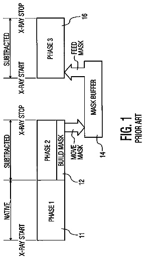
Incidentally, there are the following kinds of methods for generating a 3D geometric model of the heart. For example, as illustrated in FIG. 1, first, a physician draws boundary lines of the inner wall section of the heart muscle, the outer wall section of the heart muscle, blood vessels and the like on several hundred tomographic images, and specifies the respective parts' names. After that, the physician looks at the 3D shape according to information concerning the boundary lines and parts, gives instructions for corrections, and forms the 3D geometric model according to the correction instructions. As necessary, the physician divides the formed 3D geometric model into polygons. Incidentally, there are a lot of variations among patients for the heart position and angle and the ratio of the heart ventricles and heart atrium, and there are also differences depending on the clinical condition of a patient. Therefore, it is necessary to generate a 3D geometric model for each patient, which is close to the actual heart shape of the patient.
However, the heart is surrounded by many blood vessels, surrounding organs, bone and the like, and has a complex structure of heart muscles having different thicknesses depending on the part. In addition to those problems, there are also differences among individuals. Therefore, grasping the 3D positional information from tomographic images requires experience and knowledge in anatomy. Moreover, there are also cases in which it is difficult to distinguish boundaries due to unevenness in contrast dye or surgical scars. Therefore, except for a skilled physician, it is difficult to identify boundaries of the heart muscles, blood vessels and the like from tomographic images.
As described above, in conventional methods, in order to generate a 3D geometric model of the patient's heart, a physician having knowledge had to draw boundary lines on several hundred tomographic images. Therefore, a lot of works as well as knowledge are required.
Summary
A three-dimensional template transformation method executed by a computer, comprising: accepting designation of a part for which a three-dimensional geometric model is generated, among a heart and blood vessels surrounding the heart to obtain a three-dimensional template for a designated part from a template storage unit storing three-dimensional templates represented by polygons; first identifying a heart valve that is a reference in transformation of the three-dimensional template for the designated part; extracting a shape of an annulus of the identified heart valve from a cross-section image in a plane passing through an axis within the annulus of the identified heart valve in a three-dimensional volume data, which is generated from a plurality of tomographic images of an organism including the heart, the plurality of tomographic images being stored in a tomographic image storage unit, and storing a three-dimensional annulus data representing the annulus of the identified heart valve into a storage device; second identifying a first reference point that is a point satisfying a first condition on the annulus of the identified heart valve in the three-dimensional template for the designated part, and identifying a second reference point that is a point satisfying the first condition on the annulus represented by the three-dimensional annulus data stored in the storage device and corresponding to the first reference point; arranging, according to a predetermined rule, n starting points from the first reference point on the annulus of the identified heart valve in the three-dimensional template for the designated part, arranging, according to the predetermined rule, n target points from the second reference point on the annulus represented by the three-dimensional annulus data stored in the storage device, and storing coordinates of the starting points and the target points into the storage device, wherein the n is a predetermined integer; first calculating coefficients of a predetermined function to calculate movement destination coordinates of vertices of the polygons relating to the three-dimensional template for the designated part, by using the coordinates of the starting points and the target points, which are stored in the storage device; and second calculating the movement destination coordinates of the vertices of the polygons relating to the three-dimensional template for the designated part, by using the calculated coefficients and the predetermined function, transforming the three-dimensional template for the designated part according to the calculated movement destination coordinates, and storing the transformed three-dimensional template as a three-dimensional geometric model of the designated part into the storage device.
The object and advantages of the embodiment will be realized and attained by means of the elements and combinations particularly pointed out in the claims.
It is to be understood that both the foregoing general description and the following detailed description are exemplary and explanatory and are not restrictive of the embodiment, as claimed.
Brief description of drawings
FIG. 1 is a diagram depicting a flow of a conventional method;
FIG. 2 is a functional block diagram of a three-dimensional template transformation apparatus relating to this embodiment;
FIG. 3 is a diagram depicting an example of a 3D template;
FIG. 4 is a diagram depicting data structure of the 3D template;
FIG. 5 is a diagram depicting an example of the 3D template for a ventricle section;
FIG. 6 is a diagram depicting an example of the 3D template for a atrium section;
FIG. 7 is a diagram depicting an example of the 3D template for an aorta;
FIG. 8 is a diagram depicting an example of the 3D template for a coronary artery and coronary vein;
FIG. 9 is a diagram depicting an example of the 3D template for a heart valve;
FIG. 10 is a diagram depicting an example of data stored in a reference part data storage unit;
FIG. 11 is a diagram schematically depicting the inside of the heart and blood vessel surrounding the heart;
FIG. 12 is a diagram depicting an example when viewing the 3D template from a certain direction;
FIG. 13 is a diagram depicting an example when viewing the 3D template from a direction different from FIG. 12;
FIG. 14 is a diagram depicting an entire flow of this embodiment;
FIG. 15 is a diagram depicting tomographic images and 3D template;
FIG. 16 is a diagram depicting a main processing flow in this embodiment;
FIG. 17 is a diagram depicting data included in the 3D template for the ventricle section, atrium section, aorta or the like;
FIG. 18 is a diagram depicting an example of 3D volume data;
FIG. 19 is a diagram depicting a first portion of the processing of a line data generation processing;
FIG. 20 is a diagram depicting an example of a cross-section image in a certain slice plane;
FIG. 21 is a diagram depicting an example of edges extracted from the cross-section image;
FIG. 22 is a diagram depicting an example of line data;
FIG. 23 is a diagram depicting a second portion of the processing flow of the line data generation processing;
FIG. 24 is a diagram to explain a processing to extract the valve annulus;
FIG. 25 is a diagram depicting a third portion of the processing flow of the line data generation processing;
FIG. 26 is a diagram to explain a processing to extract the valve annulus;
FIG. 27 is a diagram depicting a three-dimensional shape of the valve annulus;
FIG. 28 is a diagram depicting examples of the line data and template data in a reference part;
FIG. 29 is a diagram depicting a first portion of a processing flow of a landmark setting processing;
FIG. 30 is a diagram to explain a processing to determine a reference point;
FIG. 31 is a diagram depicting an example of landmarks (starting point and target point);
FIG. 32 is a diagram depicting a second portion of the processing flow of the landmark setting processing;
FIG. 33 is a diagram to explain a movement vector;
FIG. 34 is a diagram depicting a processing flow of a template transformation processing;
FIG. 35 is a diagram depicting a screen example of a landmark setting screen;
FIG. 36 is a diagram depicting an example of 3D geometric model for which transformation is carried out for a plane perpendicular to a major axis of the heart;
FIG. 37 is a diagram depicting an example of the 3D geometric model for which transformation is carried out for a plane perpendicular to the major axis of the heart;
FIG. 38 is a diagram depicting a first portion of a second main processing flow of this embodiment;
FIG. 39 is a diagram to explain the major axis of the heart;
FIG. 40 is a diagram depicting a second portion of the second main processing of this embodiment;
FIG. 41 is a diagram to explain an affected range;
FIG. 42 is a diagram depicting a third portion of the second main processing flow of this embodiment;
FIG. 43 is a functional block diagram of a computer;
FIG. 44 is a diagram depicting a processing flow of the 3D template transformation method relating to a first aspect of this embodiment; and
FIG. 45 is a functional block diagram of a 3D template transformation apparatus relating to a second aspect of this technique.
Description of embodiments
FIG. 2 illustrates a functional block diagram of a 3D template transformation apparatus relating to an embodiment of this technique. The 3D template transformation apparatus relating to this embodiment has an input unit 1; tomographic image data storage unit 3; volume data generator 5; volume data storage unit 7; template processing unit 9; 3D geometric model storage unit 11; and output unit 13.
The input unit 1 receives tomographic images (for example, CT images, MRI images and the like) of a body including the heart from an imaging apparatus (not illustrated in the figure) and stores those images into the tomographic image data storage unit 3, and receives, from a user, designation of one or more parts, for which the 3D geometric model will be generated, and gives an instruction to the template processing unit 9 to start the processing. Incidentally, there are cases in which the tomographic image data storage unit 3 is included in an imaging apparatus connected via a network or another computer, and in such cases, the 3D template transformation apparatus acquires tomographic images from that image apparatus or another computer, if necessary.
The volume data generator 5 uses the data stored in the tomographic image data storage unit 3 to generate 3D volume data, and stores the generated data into the volume data storage unit 7. The output unit 13 displays the data that are stored in the volume data storage unit 7 and 3D geometric model storage unit 11 on a display or the like.
The template processing unit 9 includes a template selector 91; reference part identifying unit 92; line data generator 93; landmark setting unit 94; template transform unit 95; template data storage unit 96; reference part data storage unit 97; line data storage unit 98 and a landmark storage unit 99. After receiving an instruction from the input unit 1 to start the processing, the template processing unit 9 uses the 3D volume data that are stored in the volume data storage unit 7, and the data that are stored in the template data storage unit 96 and reference part data storage unit 97 to carry out a processing (described in detail later) to generate a 3D geometric model, and stores the generated 3D geometric model into the 3D geometric model storage unit 11.
The template data storage unit 96 stores 3D templates that include the heart and blood vessels surrounding the heart and are formed using polygons. For example, as illustrated in FIG. 3, data that represents the structural sections representing thick heart muscles, and data that represents the fluid sections representing fluid within the inner wall section of the heart muscle are stored as 3D templates. Incidentally, the shape of the heart differs among individuals, and also differs depending on the clinical state. Therefore, in this embodiment, several typical 3D templates are prepared. For example, a user is caused to input selection conditions such as gender, age, medical history (stent treatment, cardiac ventricle reduction surgery, or the like) that has had an effect on the heart or heart blood vessels and ailment (swelling of the heart, aneurism, heart valve disease, and the like), and a 3D template that matches with or is the closest to the inputted selection conditions is used for the processing.
Moreover, FIG. 4 illustrates an example of a data structure of 3D template data that is stored in the template data storage unit 96. In the example of FIG. 4, the 3D template is managed by the data structure that includes the data type, the number of vertices, the number of cells, vertex coordinates, cell structure, vertex data, and element data. In some cases, data such as label information that represents which part it is may be stored. Incidentally, as long as the data structure can manage polygon data, it is also possible to use other data structure.
FIG. 5 to FIG. 9 illustrate examples of 3D templates of the ventricle section, atrium section, surrounding blood vessels such as the aorta and coronary artery, and heart valves. FIG. 5 illustrates an example of a 3D template of the ventricle section, with the respective outer wall and inner wall of the right ventricle and left ventricle, septum between the right ventricle and left ventricle and papillary muscle in the left ventricle being represented. FIG. 6 illustrates an example of a 3D template for the atrium section, with the respective outer wall and inner wall of the right atrium and left atrium, superior vena cava, inferior vena cava, pulmonary vein, coronary vein and auricle being represented. Furthermore, FIG. 7 illustrates an example of a 3D template of the aorta, with the ascending aorta, aortic arch, descending aorta, brachiocephalic artery, left common carotid artery and left subclavian artery being represented. FIG. 8 illustrates an example of a 3D template of the coronary artery and coronary vein. Furthermore, FIG. 9 illustrates an example of a template of the heart valves, with the dark-filled sections representing the heart valves.
Data as illustrated in FIG. 10 is stored in the reference part data storage unit 97 in advance. In the example of FIG. 10, part and boundary information that becomes a reference in 3D template transformation is stored in the reference part data storage unit 97 for each part for which the model is generated. For example, in the case of the aorta, the boundaries between the aorta and each of the aortic valve annulus, coronary artery, brachiocephalic artery, left common carotid artery and left subclavian artery, and the shape of the end section of the descending aorta become a reference. In the case of the left ventricle, the aortic valve annulus, mitral valve annulus and heart apex become a reference. In the case of the left atrium, the mitral valve annulus and boundary between the left atrium and pulmonary vein become a reference. In the case of the right atrium, the tricuspid valve annulus and boundary between the right atrium and the superior and inferior vena cava become a reference. In the case of the right ventricle, the pulmonary valve annulus and tricuspid valve annulus become a reference. Incidentally, the positions of the respective heart valves and respective blood vessels are as illustrated in FIG. 11. FIG. 11 schematically illustrates the inside of the heart and the blood vessels surrounding the heart, with the parts of the heart being illustrated as a cross section such that the internal structure is easy to understand. Moreover, the arrows in FIG. 11 illustrate the direction of the blood flow. In this embodiment, there are cases in which, among the parts and boundaries that are references in 3D template transformation, boundaries other than the heart valve annulus and heart apex may be called blood vessel boundaries.
For example, FIG. 12 and FIG. 13 illustrate examples where a 3D template is viewed from different directions. In FIG. 12, the ellipse 1201 represents the boundary between the brachiocephalic artery and the aorta. In addition, the ellipse 1202 represents the boundary between the left common carotid artery and the aorta. Moreover, the ellipse 1203 represents the boundary between the left subclavian artery and the aorta. Furthermore, the ellipse 1204 represents the boundary between the right atrium and the superior vena cava. Still Further, the ellipses 1205 and 1206 respectively represent the boundary between the left atrium and the pulmonary vein. Moreover, the ellipse 1207 represents the shape of the end section of the descending aorta.
On the other hand, in FIG. 13, the ellipse 1301 represents the boundary between the brachiocephalic artery and the aorta, and the ellipse 1302 represents the boundary between the left common carotid artery and the aorta. Moreover, the ellipse 1303 represents the boundary between the left subclavian artery and the aorta. In addition, the ellipse 1304 represents the boundary between the right atrium and the superior vena cava. Furthermore, the ellipse 1305 represents the boundary between the right atrium and the inferior vena cava. In addition, the ellipses 1306 to 1309 respectively represent the boundary between the left atrium and the pulmonary vein. Moreover, the ellipse 1310 represents the shape of the end section of the descending aorta.
Next, the operation of the 3D template transformation apparatus will be explained using FIG. 14 to FIG. 42. Before explaining the detailed processing flow, the overall flow will be explained using FIG. 14. First, in step (1), the 3D template to be used this time is selected. For example, the user inputs the gender, age, medical history, ailment and the part for which the 3D geometric model is generated. The 3D templates that match with or are closest to the input gender, age, medical history and ailment are identified, and the 3D template of the part for which the 3D template is generated is selected among the identified templates as the 3D template to be used this time. For example, when only the ventricle section is designated as the part for which the 3D geometric model is generated, a 3D template such as illustrated in FIG. 5 is selected. Moreover, when only the atrium section is designated as the part for which the 3D geometric model is generated, a 3D template such as illustrated in FIG. 6 is selected. Furthermore, when only the aorta is designated as the part for which the 3D geometric model is generated, a 3D template such as illustrated in FIG. 7 is selected.
Next, in step (2), 3D volume data is generated from plural tomographic images. In step (3), rough position alignment is performed. More specifically, using the selected 3D template and the generated 3D volume data, the 3D template is transformed so that it is aligned as illustrated in FIG. 15 in order that the heart shape matches with its rough position.
In step (4), detailed shape settings are performed. More specifically, as for a certain plane, the cross-sectional image of the transformed 3D template and cross-sectional image of the 3D volume data are displayed, and the user is caused to designate pairs of a starting point and target point. The 3D template is then further transformed according to the designated pairs of the starting point and target point. If necessary, this processing is repeated for various planes. Thus, the 3D template is transformed to make it possible to generate a 3D geometric model. The detailed processing flow will be explained below.
The processing flow for the steps
to
illustrated in FIG. 14 will be explained in detail using FIG. 16 to FIG. 34. As a presumption, it is presumed that plural tomographic images of the patient have been taken and are stored in the tomographic image data storage unit 3. Furthermore, it is presumed that plural representative templates are stored in the template data storage unit 96, and data such as illustrated in FIG. 10 are stored in the reference part data storage unit 97.
First, a user, such as a physician, operates the mouse and/or keyboard to input template selection conditions on a template condition input screen (not illustrated in the figure) that is displayed on a display device. The template selection conditions include, for example, the patient ID, gender, age, medical history, ailment and parts (ventricles, atriums, aorta, heart valves, coronary arteries, coronary veins, etc.) for which the 3D geometric model is generated. Then, the input unit 1 receives the template selection conditions that were inputted by the user (FIG. 16: step S1), and stores the inputted conditions into a storage device, temporarily. When the 3D template transformation apparatus is connected to an electronic medical records system, information such as the patient's gender, age, medical history and ailment may be acquired from the electronic medical records system based on the patient ID.
Then, the template selector 91 of the template processing unit 9 selects the 3D template to be used from among the 3D templates stored in the template data storage unit 96 according to the selection conditions stored in the storage device (step S3). More specifically, the template selector 91 identifies 3D templates that match with or are the closest to those conditions, according to the gender, age, medical history and ailment, from the template data storage unit 96, and selects a 3D template of the part, for which the 3D geometric model is generated, among the identified templates, as the 3D template to be used this time. The template selector 91 acquires data of the selected 3D template from the template data storage unit 96, and uses this template in the following processing.
For example, as illustrated in FIG. 17, the 3D templates of the ventricle section include data that represents the left ventricle (inner wall and outer wall of the left ventricle, papillary muscle and chordae tendineae), the right ventricle (inner wall and outer wall of the right ventricle), the heart muscles boundaries (boundary between the left ventricle and right ventricle, boundary between the left ventricle and left atrium, boundary between the right ventricle and right atrium and boundary between the left ventricle and aorta), fluid boundaries (boundary between the left ventricle and left atrium, boundary between the right ventricle and right atrium and boundary between the left ventricle and aorta boundary), the pulmonary artery (inner wall, outer wall and respective boundaries) and septum. In addition, the 3D templates for the atrium section include data that represents the left atrium (inner wall and outer wall of the left atrium), right atrium (inner wall and output wall of the right atrium), cardio-vascular system (inner walls, output walls of the superior vena cava, inferior vena cava, pulmonary vein and respective boundaries of them) and heart muscles boundary (boundary between the left atrium and right atrium). Furthermore, 3D templates for the aorta section include data that represents the descending aorta (inner wall, outer wall and respective boundaries), ascending aorta (inner wall, outer wall and respective boundaries), the aortic arch (inner wall, outer wall and respective boundaries), brachiocephalic artery (inner wall, outer wall and respective boundaries), left common carotid artery (inner wall, outer wall and respective boundaries) and left subclavian artery (inner wall, outer wall and respective boundaries). In addition to this, when the coronary arteries, coronary veins and heart valves (mitral valve, tricuspid valve, aortic valve and pulmonary valve) are designated as the parts for which the 3D geometric model is generated, these 3D templates are used.
Then, the volume data generator 5 generates 3D volume data from the tomographic images that are stored in the tomographic image data storage unit 3, and stores the generated data into the volume data storage unit 7 (step S5). For example, the volume data generator 5 generates 3D volume data using techniques such as linear interpolation or polynomial interpolation. FIG. 18 illustrates an example of 3D volume data that is generated from tomographic images. The method for generating 3D volume data is a well-known technique. Therefore, further explanation is omitted here. Moreover, the processing of the steps S3 and S5 may be carried out in parallel, or may be carried out in reverse order.
Then, the reference part identifying unit 92 of the template processing unit 9 searches the reference part data storage unit 97 based on the information about the part for which the 3D geometric model is generated, and which is stored in the storage device, and identifies the parts (i.e. boundaries) that will be the reference when transforming the 3D template that was selected at the step S3 as the reference parts (step S7). For example, when the ventricles (left ventricle and right ventricle) are included in the parts for which the 3D geometric model is generated, the aortic annulus, mitral annulus, heart apex, pulmonary valve annulus and tricuspid valve annulus are identified from the reference part data storage unit 97 (FIG. 10) as the reference parts. When the atriums (left atrium and right atrium) are included in the parts for which the 3D geometric model is generated, the mitral valve annulus, boundary between the left atrium and pulmonary vein, the tricuspid valve annulus and the boundary between the right atrium and superior and inferior vena cava are identified from the reference part data storage unit 97 as reference parts. Furthermore, when the aorta is included in the parts for which the 3D geometric model is generated, the aortic valve annulus and the boundaries between the aorta and each of the coronary artery, the brachiocephalic artery, the left common carotid artery and left subclavian artery, and the shape of the end section of the descending aorta are identified from the reference part data storage unit 97 as reference parts. Incidentally, when the heart and all of the blood vessels surrounding the heart are parts for which the 3D geometric model is generated, all of the parts (i.e. boundaries) set in the reference part data storage unit 97 become the reference parts. By setting characteristic parts such as the heart valves or boundaries of the cardio-vascular system as references, it is possible to suitably transform the 3D template.
The line data generator 93 then uses the data stored in the volume data storage unit 7 and template data storage unit 96 to carry out a line data generation processing (step S9). The line data generation processing will be explained by using FIG. 19 to FIG. 27.
First, the line data generator 93 identifies one unprocessed part from the reference parts (FIG. 19: step S21), and determines whether or not the identified reference part is a blood vessel boundary (step S23).
When the identified part is a blood vessel boundary (step S23: YES route), the line data generator 93 displays information representing which blood vessel boundary it is and 3D volume data on the display device, and prompts the user to designate the position of the slice plane in the 3D volume data, which corresponds to the blood vessel boundary. The user operates the mouse and/or keyboard, and designates the position in the slice plane that corresponds to the blood vessel boundary, while viewing the 3D volume data. Incidentally, when the user looks at the 3D volume data, the user can recognize a 3D heart shape. Therefore, the user can easily designate the position in the slice plane that corresponds to the blood vessel boundary. The input unit 1 then receives, from the user, the designation of the position of the slice plane (step S25), and outputs the position information of the designated slice plane to the line data generator 93.
Then, when the line data generator 93 receives the position information of the slice plane from the input unit 1, the line data generator 93 generates cross-section image data of the slice plane from the 3D volume data, and stores the generated data into the storage device (step S27). FIG. 20 illustrates an example of the cross-section image of a certain slice plane. The line data generator 93 then carries out edge extraction on the cross-section image (step S29). For example, the edges (i.e. contours) of the parts that are presumed to be the heart or blood vessels are extracted according to brightness values in the cross-section image or the like. FIG. 21 illustrates an example of the processing results of the edge extraction. Incidentally, in FIG. 21, the solid border lines indicate the extracted edges. The edge extraction is a well-known technique. Therefore, further explanation is omitted, here.
The line data generator 93 then displays the processing results of the edge extraction on the display device, and prompts the user to designate the edges corresponding to the blood vessel boundary. The user operates the mouse and/or keyboard, and designates the edges corresponding to the blood vessel boundaries, from among the displayed edges. Then, the input unit 1 receives the designation of the edges corresponding to the blood vessel boundaries (step S31), and outputs the identification information of the designated edges to the line data generator 93.
When the line data generator 93 receives the identification information from the input unit 1, the line data generator 93 associates the line data that represents the edges with information representing the blood vessel boundary, and stores the association information into the line data storage unit 98. FIG. 22 illustrates an example of the line data. After that, the processing moves to the processing of step S37.
On the other hand, when it is determined at the step S23 that the designated reference part is not a blood vessel boundary (step S23: NO route), the line data generator 93 determines whether or not the designated reference part is an annulus of a heart valve (step S35). When the designated reference part is not an annulus of a heart valve (step S35: NO route), or in other words, when the designated part is a heart apex, the processing moves to the processing of the step S37.
On the other hand, when the designated reference part is an annulus of a heart valve (step S35: YES route), the processing moves to the processing of step S39 (FIG. 23) via a terminal A.
Moving to explanation of FIG. 23, after the terminal A, the line data generator 93 displays information representing which heart valve it is and 3D volume data on the display device, and prompts the user to designate the position of the heart valve, and a reference axis that is an axis that passes through the inside of the annulus of that heart valve. The user operates the mouse and/or keyboard, and while looking at the 3D volume data, the user designates the position of the heart valve and the reference axis that passes through the inside of the annulus of that heart valve. Then, the input unit 1 receives the designation of the position of the heart valve and the reference axis that passes through the inside of the annulus of that heart valve from the user (FIG. 23: step S39), and outputs the position information of the heart valve and reference axis to the line data generator 93.
When the line data generator 93 receives the position information of the heart valve and reference axis from the input unit 1, the line data generator 93 sets the reference axis as the z axis (step S41). Then, according to the position information of the heart valve designated by the user, the line data generator 93 extracts a partial area that includes the heart valve from 3D volume data after the direction has been changed (step S43), and stores the data of the partial area into the storage device.
After that, the line data generator 93 identifies the starting plane from among the planes that pass through the z axis, generates cross-section image data of the starting plane and stores the generated data into the storage device (step S45). The line data generator 93 then displays the cross-section image data on the display device, and prompts the user to designate the part corresponding to the valve annulus. While looking at the cross-section image, the user designates the part that corresponds to the valve annulus. For example, as illustrated in FIG. 24, the user designates two parts that correspond to the valve annulus. Incidentally, in FIG. 24, the white circles represent the parts that the user designated. The input unit 1 then receives the designation of the parts in the cross-section image, which correspond to the annulus (step S47), and outputs the position information of the designated parts to the line data generator 93. After that, the processing moves to the processing of step S49 (FIG. 25) via a terminal B.
Moving to explanation of FIG. 25, after the terminal B, the line data generator 93 sets the cross-section image of the current plane as the template to be used for pattern matching (FIG. 25: step S49). The line data generator 93 then identifies a plane that has been rotated a predetermined angle (for example, 5 degrees) from the current plane with the z axis as the axis of rotation (step S51). After that, the line data generator 93 determines whether or not the plane has rotated 180 degrees from the starting plane (step S53). In other words, the line data generator 93 determines whether or not the plane identified at the step S51 is the same plane as the starting plane. When the plane has not been rotated 180 degrees from the starting plane (step S53: NO route) the line data generator 93 generates cross-section image data for the identified plane (in other words, the rotated plane), and stores the generated data into the storage device, temporarily (step S55). The line data generator 93 then identifies the part corresponding to the valve annulus in the cross-section image by carrying out the pattern matching with cross-section images stored in the storage device and the template (step S57). After that, the processing returns to the step S49. In other words, the line data generator 93 sets the cross-section image of the current plane as the template, carries out the pattern matching of the template with the cross-section image of the next plane that is rotated a predetermined angle, and identifies the two parts (two locations) that correspond to the valve annulus. As illustrated in FIG. 26, the plane is gradually rotated from the starting plane until the plane has been rotated 180 degrees (or in other words, until the plane returns to the starting plane), and the processing of the steps S49 to S57 is repeated.
On the other hand, when it is determined at the step S53 that the designated plane has been rotated 180 degrees from the starting plane (step S53: YES route), the line data generator 93 generates line data representing the shape of the valve annulus section by connecting the parts corresponding to the valve annulus, and then stores the generated line data into the line data storage unit 98 in association with information representing which annulus of the heart values it is (step S59). For example, the mitral valve annulus has a saddle type shape as illustrated in FIG. 27. In this embodiment, as described above, by carrying out the processing by rotating the plane gradually at predetermined angles around the z axis as the axis of rotation, the 3D shape of the valve annulus section is extracted and line data that represents that 3D shape is stored. After that, the processing moves to the processing of the step S37 via a terminal C.
Returning to the explanation of FIG. 19, the line data generator 93 determines whether or not the processing for all of the reference parts has been completed (step S37). When the processing for all of the reference parts has not been completed (step S37: NO route), the processing returns to the processing of the step S21, and the processing described above is repeated until the processing for all of the reference parts has been completed.
On the other hand, when the processing for all of the reference parts has been completed (step S37: YES route), this processing ends, and the processing returns to the calling source processing.
By carrying out the line data generation processing as described above, it is possible to generate line data that represents the 3D shape of the valve annulus section for a heart valve annulus, and it is possible to generate the line data that represents the 2D shapes of the blood vessel boundaries.
Returning to the processing of FIG. 16, after carrying out the line data generation processing (step S9), the landmark setting unit 94 of the template processing unit 9 uses data stored in the template data storage unit 96 and line data storage unit 98 to carry out a landmark setting processing (step S11). In the landmark setting processing, the landmark setting unit 94 correlates, for each reference part, the shape of the reference part that is represented by the line data with the shape of the applicable reference part in the 3D template to set landmarks (i.e. starting points and target points). FIG. 28 illustrates an example of the line data for each of the reference parts and template data. The landmark setting processing will be explained in detail using FIG. 29 to FIG. 32.
First, the landmark setting unit 94 identifies one unprocessed part from among the reference parts (FIG. 29: step S61), and determines whether or not the identified reference part is a blood vessel boundary (step S63).
When the identified reference part is a blood vessel boundary (step S63: YES route), the landmark setting unit 94 acquires line data relating to the identified reference part (i.e. blood vessel boundary) from the line data storage unit 98 (step S65). The landmark setting unit 94 also acquires template data relating to the identified reference part (i.e. blood vessel boundary) from the template data storage unit 96 (step S67). Incidentally, the processing of steps S65 and S67 may be executed in parallel or in reverse order.
The landmark setting unit 94 then identifies reference points for associating the edges on each of the edges of the blood vessel boundaries represented by the line data and the edges of the blood vessel boundaries in the template data (step S69). For example, since the blood vessel boundaries have an elliptical or a shape close to elliptical, correlation is carries out such that the major axes and the minor axes of them respectively correspond. As illustrated in FIG. 30, the landmark setting unit 94 sets a point in the 12 o'clock direction (i.e. intersection with the minor axis) as the reference point. The method for setting the reference point is not limited to this, and it is possible to employ other methods.
The description continues in the full USPTO document.
 Lapsed, fee not paid3 drawings