Field of the invention
Embodiments of the present invention generally pertain to implantable medical devices and more particularly to methods and systems that adjust a stimulation rate at which stimulus pulses are supplied to a heart.
Background of the invention
An implantable medical device (IMD) is implanted in a patient to monitor, among other things, electrical activity of a heart and to deliver appropriate electrical therapy, as required. Implantable medical devices include pacemakers, cardioverters, defibrillators, implantable cardioverter defibrillators (ICD), and the like. The electrical therapy produced by an IMD may include pacing pulses, cardioverting pulses, and/or defibrillator pulses to reverse arrhythmias (e.g., tachycardias and bradycardias) or to stimulate the contraction of cardiac tissue (e.g., cardiac pacing) to return the heart to its normal sinus rhythm. These pulses are referred to as stimulus or stimulation pulses.
Some IMDs supply a pacing therapy to hearts to treat ventricular tachycardia and/or ventricular fibrillation. The pacing therapy may include supplying stimulus pulses to the left and right ventricles of the heart at a stimulation rate. Applying the stimulus pulses to the ventricles may restore mechanical synchrony to the heart. For example, the stimulus pulses may return the heart to a normal rate of ventricular contraction.
Pacing therapies of some known IMDs monitor cardiac signals of the heart to determine when to supply stimulus pulses. For example, after detecting a paced or intrinsic cardiac event, such as a ventricular contraction, the IMD continues to monitor the cardiac signals to determine if a subsequent intrinsic cardiac event occurs during a predetermined escape interval after the preceding cardiac event. If no subsequent cardiac event is detected during the predetermined escape interval, then the IMD supplies a stimulus pulse to the heart to induce contraction of the heart.
During ventricular tachycardia or ventricular fibrillation, intrinsic ventricular contractions may not provide the same level of cardiac output as paced ventricular contractions, or ventricular contractions that are induced by the delivery of stimulus pulses to one or more of the ventricles. For example, intrinsic ventricular contractions may pump less blood through the heart when compared to paced ventricular contractions during ventricular tachycardia or ventricular fibrillation.
Some known IMDs increase the stimulation rate at which stimulus pulses are applied to the heart to increase the number of paced contractions and decrease the number of intrinsic contractions. The IMDs monitor intrinsic and paced ventricular contractions during ventricular tachycardia and ventricular fibrillation in order to determine the stimulation rate. The IMDs determine the stimulation rate based on the predetermined escape interval. For example, the IMDs may decrease the escape interval of a ventricle for subsequent cardiac cycles when an intrinsic ventricular contraction is sensed during the escape interval of a current cardiac cycle. The escape interval is decreased to increase the possibility that the escape interval expires and the IMD delivers a stimulus pulse prior to intrinsic ventricular contraction. For example, decreasing the escape interval provides a shorter time in which an intrinsic contraction must occur before the IMD delivers a stimulus pulse to the heart. On the other hand, an IMD may increase the escape interval if the IMD has been pacing the heart for at least a predetermined time period. The IMD increases the escape interval to reduce the stimulation rate and avoid pacing the heart at an accelerated rate for greater than the predetermined time period.
The known IMDs described above do not, however, account for the presence of fusion-based behavior of the heart. Fusion-based behavior of the heart may reduce the cardiac output of the heart. Reducing the cardiac output of the heart during a pacing therapy may prolong the therapy or fail to remedy the ventricular tachycardia or ventricular fibrillation. Fusion-based behavior may include fusion and pseudo-fusion between paced and intrinsic cardiac events. Fusion may occur when a stimulus pulse is applied to a heart chamber at approximately the same time that an intrinsic contraction of the heart chamber begins. Pseudo-fusion may occur when a stimulus pulse is applied to the heart chamber shortly after an intrinsic contraction of the heart chamber begins. By failing to account for the presence of fusion-based behavior while pacing the heart, some known IMDs continue to ineffectively pace the heart.
Brief summary of the invention
In one embodiment, an implantable medical device is provided. The device includes a lead, a pulse generator, a cardiac signal module, a fusion detection module and a rate modification module. The lead includes electrodes that are configured to be positioned within a heart to sense cardiac signals of the heart. The pulse generator delivers stimulus pulses to the heart through at least one of the electrodes. The cardiac signal module monitors the cardiac signals and directs the pulse generator to deliver one or more of the stimulus pulses to the heart at a stimulation rate based on the cardiac signals. The fusion detection module identifies a presence of fusion-based behavior of the heart that is associated with delivery of the one or more of the stimulus pulses. The rate modification module then adjusts the stimulation rate based on the presence of the fusion-based behavior.
In another embodiment, a method for adjusting a stimulation rate at which an implantable medical device applies stimulus pulses to a heart is provided. The method includes monitoring cardiac signals of the heart and delivering one or more stimulus pulses to the heart at the stimulation rate based on the cardiac signals. The method also includes identifying a presence of fusion-based behavior of the heart that is associated with delivery of the one or more of the stimulus pulses and adjusting the stimulation rate based on the presence of the fusion-based behavior.
In another embodiment, a computer readable storage medium for use in an implantable medical device having a lead including electrodes configured to be positioned within a heart, a pulse generator to deliver stimulus pulses to the heart, and a microcontroller is provided. The computer readable storage medium includes instructions to direct the microcontroller to monitor cardiac signals of the heart using one or more of the electrodes and to instruct the pulse generator to deliver one or more stimulus pulses to the heart at a stimulation rate using at least one of the electrodes when consecutive cardiac events occur outside of an escape interval. The instructions also direct the microcontroller to identify a presence of fusion-based behavior of the heart that is associated with delivery of the one or more of the stimulus pulses and to adjust the stimulation rate based on the presence of the fusion-based behavior.
Brief description of the drawings
The drawings illustrate generally, by way of example, but not by way of limitation, various embodiments discussed in the present document.
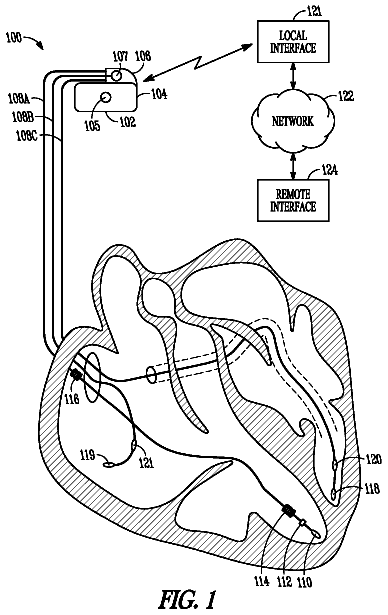
FIG. 1 illustrates an implantable medical device (IMD) coupled to a heart in accordance with one embodiment.
FIG. 2 illustrates an example of a cardiac signal of the heart that is sensed by the IMD shown in FIG. 1.
FIG. 3 illustrates a method for adjusting an escape interval of the IMD shown in FIG. 1 according to one embodiment.
FIG. 4 illustrates a cardiac signal of the heart that is representative of an evoked response of the heart.
FIG. 5 illustrates a block diagram of exemplary internal components of the IMD shown in FIG. 1.
FIG. 6 illustrates a functional block diagram of an external device (shown in FIG. 5) in accordance with one embodiment.
FIG. 7 illustrates a distributed processing system in accordance with one embodiment.
FIG. 8 illustrates a block diagram of example manners in which embodiments of the present invention may be stored, distributed, and installed on a computer-readable medium.
Detailed description of the invention
In the following detailed description, reference is made to the accompanying drawings which form a part hereof, and in which are shown by way of illustration specific embodiments in which the present invention may be practiced. These embodiments, which are also referred to herein as "examples," are described in sufficient detail to enable those skilled in the art to practice the invention. It is to be understood that the embodiments may be combined or that other embodiments may be utilized, and that structural, logical, and electrical variations may be made without departing from the scope of the present invention. The following detailed description is, therefore, not to be taken in a limiting sense, and the scope of the present invention is defined by the appended claims and their equivalents. In this document, the terms "a" or "an" are used, as is common in patent documents, to include one or more than one. In this document, the term "or" is used to refer to a nonexclusive or, unless otherwise indicated.
In accordance with certain embodiments, methods and systems are provided for adjusting a stimulation rate at which stimulus pulses are applied to a heart. The stimulation rate may be adjusted based on the presence of fusion-based behavior that is identified in the heart after delivery of one or more of the stimulus pulses to the heart.
FIG. 1 illustrates an implantable medical device (IMD) 100 coupled to a heart 102 in accordance with one embodiment. The IMD 100 may be a cardiac resynchronization therapy (CRT) pacemaker. Alternatively, the IMD 100 may be a cardiac pacemaker, an ICD, a defibrillator, an ICD coupled with a pacemaker, a cardiac resynchronization therapy defibrillator (CRT-D), and the like. The IMD 100 includes a housing 110 that is joined to several leads 104, 106, 108. The leads 104, 106, 108 are located at various locations of the heart 102, such as an atrium, a ventricle, or both, to measure cardiac signals of the heart 102 and to deliver stimulus pulses, such as pacing pulses. The leads 104, 106, 108 include the right ventricular (RV) lead 104, the right atrial (RA) lead 106, and the coronary sinus lead 108. Several electrodes are coupled with the leads 104, 106, 108 for sensing cardiac signals and/or for delivering stimulus or stimulation pulses to the heart 102. The housing 110 may be one of the electrodes and may be referred to as the "can", "case", or "case electrode."
The RV lead 104 is coupled with an RV tip electrode 122, an RV ring electrode 124, and an RV coil electrode 126. The RV lead 104 may include a superior vena cava (SVC) coil electrode 128. The right atrial lead 106 includes an atrial tip electrode 112 and an atrial ring electrode 114. The coronary sinus lead 108 includes a left ventricular (LV) tip electrode 116, one or more left atrial (LA) ring electrodes 118 and an LA coil electrode 120. Alternatively, the coronary sinus lead 108 may be a quadropole lead that includes several electrodes 130 disposed within the left ventricle and along the lead 108 between the LV tip electrode 116 and the LA ring electrode 118. Leads and electrodes other than those shown in FIG. 1 may be included in the IMD 100 and positioned in or proximate to the heart 102.
The IMD 100 monitors cardiac signals of the heart 102 to determine if and when to deliver stimulus pulses to one or more chambers of the heart 102. The IMD 100 may deliver pacing stimulus pulses to pace the heart 102 and maintain a desired heart rate and/or shocking stimulus pulses to treat an abnormal heart rate. The stimulus pulses can be applied to the left and/or right ventricles of the heart 102 to treat ventricular tachycardia and/or ventricular fibrillation, for example. For example, if the IMD 100 senses activity in a chamber of the heart 102 but does not sense additional activity in the chamber within a predetermined time period or window, the IMD 100 may apply a stimulus pulse to the chamber to cause polarization or contraction of the chamber.
FIG. 2 illustrates an example of cardiac signals 200, 250 of the heart 102 (shown in FIG. 1) that are sensed by the IMD 100 (shown in FIG. 1). The cardiac signal 200 represents cardiac activity of the left ventricle of the heart 102 while the cardiac signal 250 represents cardiac activity of the right ventricle of the heart 102. The cardiac signals 200, 250 are shown alongside horizontal axes 202, 252 that are representative of time and vertical axes 204, 254 that are representative of the strength or magnitude of the cardiac signals 200, 250. The cardiac signals 200, 250 may be offset above or below the horizontal axes 202, 252.
The cardiac signals 200, 250 include R-waves 206, 256 that correspond to intrinsic ventricular activity. For example, the R-wave 206 may represent intrinsic ventricular contraction of the left ventricle while the R-wave 256 represents intrinsic ventricular contraction of the right ventricle. The R-waves 206, 256 may represent cardiac activity that is not caused by application of a stimulus pulse. Alternatively, the R-waves 206, 256 may represent activity of a different chamber of the heart 102 (shown in FIG. 1). The waveforms of the R-waves 206, 256 include positive deflection portions 210, 260 followed by negative deflection portions 212, 262. The R-waves 206, 256 occur over a time period referred to as an electrical depolarization time 214, 264. The electrical depolarization time 214 of the R-wave 206 includes both the positive and negative deflection portions 210, 212 and the electrical depolarization time 264 includes both the positive and negative deflection portions 260, 262 of the R-wave 256. The electrical depolarization times 214, 264 represent the time period or window over which the left and right ventricles electrically depolarize. While the electrical depolarization times 214, 264 may vary among patients, in general, each of the electrical depolarization times 214, 264 is approximately 75 milliseconds. For example, the electrical depolarization times 214, 264 may be longer for hearts 102 with conduction problems such as left or right bundle branch block
The IMD 100 (shown in FIG. 1) monitors one or more of the cardiac signals 200, 250 to determine if consecutive cardiac events occur within an escape interval 216. The escape interval 216 is a time window or period that commences at the detection of the R-wave 206, 250 and lasts for a predetermined amount of time. In the illustrated embodiment, with respect to the left ventricle, the escape interval 216 is a ventricular escape interval that begins when the R-wave 206 exceeds a predetermined detection threshold 236. With respect to the right ventricle, the escape interval 216 begins when the R-wave 256 exceeds a predetermined detection threshold 238.
The escape interval 216 is used to determine when to apply a stimulus pulse to the heart 102 (shown in FIG. 1). For example, the escape interval 216 may be used to determine if consecutive R-waves occur within the time period defined by the escape interval 216. In the example shown in FIG. 2, with respect to the left ventricle, the escape interval 216 begins with the detection of the R-wave 206. If the IMD 100 (shown in FIG. 1) senses cardiac activity, such as a subsequent left ventricular R-wave 208, within the escape interval 216 following the previous left ventricular R-wave 206, then the IMD 100 does not apply a stimulus pulse to the heart 102. With respect to the right ventricle, the escape interval 216 begins with the detection of the R-wave 256. If the IMD 100 senses cardiac activity, such as a subsequent right ventricular R-wave 258 within the escape interval 216 following the previous right ventricular R-wave 256, then the IMD 100 does not apply a stimulus pulse to the heart 102. Typically, the IMD 100 looks for ventricular activity in one ventricular configuration for ventricular timing. This ventricular configuration could be a right ventricular sensing configuration, such as sensing using the right ventricular RV tip electrode 122 to the right ventricular RV ring electrode 124. Alternatively, the sensing configuration could be a left ventricular sensing configuration, such as sensing using the left ventricular LV tip electrode 116 to the left ventricular ring electrode 130. Following the delivery of the stimulus pulses in the right ventricle and left ventricle, however, independent sensing of the right ventricle and left ventricle, respectively, may occur. It is this sensing following pacing events that may be used to determine fusion, or if fusion-based behavior has occurred, even if the sensing for ventricular timing uses only one configuration for ventricular sensing.
On the other hand, if the escape interval 216 following an R-wave lapses before the IMD 100 (shown in FIG. 1) senses cardiac activity, then the IMD 100 delivers a stimulus pulse to the heart 102 (shown in FIG. 1). With respect to the example shown in FIG. 2, an escape interval 216 that begins with the detection of the subsequent right ventricular R-wave 258 expires without an additional intrinsic cardiac event being sensed by the IMD 100 in the right ventricle. For example, the escape interval 216 expires without an additional subsequent R-wave being detected by the IMD 100 in the right ventricle. As a result, the IMD 100 delivers one or more stimulus pulses to the heart 102. If the IMD 100 is pacing both ventricles of the heart 102, the IMD 100 may deliver an LV stimulus pulse 240 to the left ventricle at a left ventricular pacing time 218 and an RV stimulus pulse 242 to the right ventricle at a right ventricular pacing time 220. The pacing times 218, 220 are separated in time from one another by an interchamber paced delay 222.
The IMD 100 (shown in FIG. 1) continues to monitor cardiac activity of the left and right ventricles for additional cardiac events. The time period between consecutive cardiac events is referred to as an event interval. The event interval begins with the start of a paced or intrinsic cardiac event and terminates with the beginning of the subsequent paced or intrinsic cardiac event. For example, a first event interval 232 begins with detection of the LV R-wave 206 and ends with the detection of the subsequent LV R-wave 208. A second event interval 234 starts with the detection of the subsequent LV R-wave 208 and ends with the application of the LV stimulus pulse 240 at the left ventricular pacing time 218.
The IMD 100 (shown in FIG. 1) determines if additional cardiac activity in either of the left or right ventricles occurs within the escape interval 216 following delivery of a stimulus pulse. For example, the IMD 100 monitors cardiac signals of the left ventricle over the escape interval 216 following the LV stimulus pulse 240 to determine if the left ventricle depolarizes during the escape interval 216. The IMD 100 also may monitor cardiac signals of the right ventricle over the escape interval 216 following the RV stimulus pulse 242 to determine if the right ventricle depolarizes during the escape interval 216.
In the example shown in FIG. 2, the escape interval 216 following the LV stimulus pulse 240 expires without detection of additional activity of the left ventricle. As a result, the IMD 100 delivers another LV stimulus pulse 244 at a left ventricular pacing time 246 and another RV stimulus pulse at a right ventricular pacing time 266. As described above, the LV and RV stimulus pulses are separated in time by the interchamber paced delay 222. In the signals 200, 250 shown in FIG. 2, the previous RV stimulus pulse 242 that was delivered at the right ventricular pacing time 220 causes depolarization of the right ventricle. The paced depolarization of the right ventricle occurs during the same time period or window that the additional RV stimulus pulse is applied at the right ventricular pacing time 266. For example, the paced depolarization of the right ventricle may begin during the interchamber paced delay 222. As a result, the paced depolarization of the right ventricle and the additional RV stimulus pulse that is applied at the pacing time 266 become fused with one another. A fused waveform 268 represents the fusion of the paced depolarization of the right ventricle and the RV stimulus pulse applied at the pacing time 266.
In one embodiment, fusion-based behavior of the heart 102 (shown in FIG. 1) includes the occurrence of one or more of a fusion paced event and a pseudo-fusion paced event. Fusion-based behavior occurs when a stimulus pulse is delivered to the heart 102 by the IMD 100 (shown in FIG. 1) at approximately the same time that an intrinsic cardiac event occurs. For example, a paced fusion event may occur when an intrinsic depolarization or contraction of a chamber of the heart 102 begins at approximately the same time as a stimulus pulse is delivered to the chamber. A paced pseudo-fusion event may occur when a stimulus pulse is delivered to the heart chamber shortly after intrinsic depolarization or contraction of the chamber begins.
The IMD 100 may measure the time period over which the heart 102 depolarizes after application of a stimulus pulse to a ventricle. For example, the time period over which the heart 102 depolarizes after application of the RV stimulus pulse 242 at the right ventricular pacing time 220 may be measured as a paced depolarization time 230. Alternatively, the paced depolarization time 230 may be a predetermined time period stored in a memory accessible by the IMD 100.
In order to avoid fusion-based behavior in the heart 102 (shown in FIG. 1) during abnormal cardiac behavior such as an atrial arrhythmia (e.g., atrial tachycardia or atrial fibrillation) that is conducting into the ventricles intermittently, the IMD 100 (shown in FIG. 1) may adjust the stimulation rate, or the frequency, at which the ventricular stimulus pulses are applied to the heart 102 based on the presence of fusion-based behavior in the heart 102. For example, the IMD 100 may increase the stimulation rate at which stimulus pulses are applied to the ventricles when fusion-based behavior is detected in the heart 102. Alternatively, the IMD 100 may monitor cardiac signals for fusion-based behavior without modifying the stimulation rate. For example, the IMD 100 may apply stimulus pulses during an atrial arrhythmia and monitor the cardiac signals on a beat-by-beat basis to determine if fusion-based behavior is present without adjusting the rate at which the stimulus pulses are supplied. In one embodiment, the IMD 100 adjusts the stimulation rate by modifying the escape interval 216. The stimulation rate may be increased by decreasing the escape interval 216. For example, the escape interval 216 is the period of time over which the IMD 100 monitors cardiac signals of the heart 102 to determine if a cardiac event, such as ventricular contraction, is detected within the escape interval 216, as described above. If the escape interval 216 is decreased, the IMD 100 monitors the cardiac signals of the heart 102 for intrinsic cardiac activity for a shorter period of time before applying stimulus pulses to the heart 102. As the IMD 100 monitors cardiac signals for a shorter period of time before applying stimulus pulses, the stimulus pulses are applied to the heart 102 more rapidly, or at an increased stimulation rate.
FIG. 3 illustrates a method 400 for adjusting a ventricular escape interval of an IMD 100 (shown in FIG. 1) according to one embodiment. At 408, the IMD 100 (shown in FIG. 1) monitors cardiac signals of the ventricles of the heart 102 (shown in FIG. 1). For example, the IMD 100 may monitor cardiac signals representative of ventricular activity of the heart 102 to identify intrinsic ventricular contractions of the heart 102. The cardiac signals also may be monitored to determine the cardiac rate of the heart 102. The cardiac rate is used to determine an escape interval 216 (shown in FIG. 2) of the heart 102 (shown in FIG. 1). As described above, the escape interval 216 is used by the IMD 100 (shown in FIG. 1) to determine whether to supply a stimulus pulse to a chamber of the heart 102. The escape interval 216 may be derived based on the cardiac rate. For example, the escape interval 216 may be measured as the time period extending between consecutive ventricular contractions. The IMD 100 may calculate the escape interval 216 as the time between R-waves 206, 208 (shown in FIG. 2), such as the first event interval 232 (shown in FIG. 2), as described above. Alternatively, a predetermined time period may be used for the escape interval 216. For example, the escape interval 216 may be set to a predetermined value obtained from a memory accessible by the IMD 100.
At 410, after sensing an intrinsic cardiac event, such as an intrinsic ventricular contraction, the IMD 100 continues to monitor the cardiac signals to determine if the escape interval 216 (shown in FIG. 2) lapses without sensing an additional intrinsic cardiac event. For example, the IMD 100 monitors the cardiac signals to determine whether another intrinsic ventricular contraction occurs or begins during the escape interval 216 following the previously sensed ventricular contraction. Flow of the method 400 continues along one of at least two paths 412, 414 depending on whether an additional intrinsic cardiac event is sensed during the escape interval 216. For example, if the escape interval 216 expires before the IMD 100 senses the beginning or presence of an intrinsic cardiac event, then flow of the method 400 continues along a pacing path 412. The escape interval 216 may expire before the IMD 100 senses a subsequent cardiac event when the subsequent cardiac event commences outside of the escape interval 216. On the other hand, if the IMD 100 senses the beginning or occurrence of an intrinsic cardiac event during the escape interval 216, the flow of the method 400 continues along a sensed event path 414.
With respect to the pacing path 412, at 416, a stimulus pulse is delivered to one or more chambers of the heart 102 (shown in FIG. 1). For example, the IMD 100 (shown in FIG. 1) may apply stimulus pulse(s) to one or more of the left and right ventricles of the heart 102. The stimulus pulses are supplied to the heart 102 to induce contraction of the corresponding chambers of the heart 102, as described above. At 418, cardiac signals of the heart 102 (shown in FIG. 1) are examined to determine whether the cardiac signals indicate fusion-based behavior of the heart 102. For example, the IMD 100 (shown in FIG. 1) may monitor cardiac signals after the stimulus pulse(s) are applied to the heart 102 at 416 to identify fusion-based behavior of the heart 102 associated with delivery of the stimulus pulse(s). As described above, fusion-based behavior includes fusion paced events and pseudo-fusion paced events. One or more of several techniques and methods may be used to identify fusion-based behavior of the heart 102. The techniques and methods discussed herein are provided as examples only.
With continued reference to the method 400 shown in FIG. 3, FIG. 4 illustrates a cardiac signal 500 of the heart 102 (shown in FIG. 1) representative of an evoked response of the heart 102. The cardiac signal 500 is shown alongside a horizontal axis 502 representative of time and a vertical axis 504 representative of sensed electrical voltage of the heart. In the illustrated embodiment, a baseline 516 of the cardiac signal 500 is coextensive with the horizontal axis 502. Alternatively, the baseline 516 may be biased above or below the horizontal axis 502. The cardiac signal 500 represents an evoked response of the heart 102 to application of a stimulus pulse to one or more chambers of the heart 102. The cardiac signal 500 may be examined at 418 to determine whether the heart 102 is demonstrating fusion-based behavior in response to application of the stimulus pulse applied at 416.
The cardiac signal 500 includes a paced event 506 that is illustrated as a waveform spike. The paced event 506 represents delivery of a stimulus pulse to the heart 102 (shown in FIG. 1) at 416. This pacing spike may or may not be sensed by the activity of the heart 102 as the electronics of delivering the pacing spike may be tuned to prevent the observation of the pacing voltage by the sensing elements of the IMD 100 (shown in FIG. 1). An evoked response waveform 508 follows the paced event 506 and includes a negative portion 510 and a positive portion 512. In one embodiment, the evoked response waveform 508 may be examined at 418 to determine whether the heart 102 is demonstrating fusion-based behavior. One or more of a paced depolarization integral (PDI) 514 and Dmax parameter 518 may be examined at 418 to determine if fusion-based behavior exists. PDI 514 is the area of the negative portion 510 of the evoked response waveform 508. The PDI 514 is represented as the absolute value of the area between the negative portion 510 and the baseline 516 of the cardiac signal 500. The Dmax parameter 518 represents the value of the slope of a positive-sloped section 520 of the evoked response waveform 508 from the negative portion 510 toward the positive portion 512. The positive-sloped section 520 of the evoked response waveform 508 begins subsequent to a low point 522 of the negative portion 510 and extends to the baseline 516 of the evoked response waveform 508. The Dmax parameter 518 is shown as a dashed line in FIG. 4.
In one embodiment, the values of the PDI 514 and the Dmax parameter 518 are measured by the IMD 100 (shown in FIG. 1) and compared to associated thresholds to determine if the heart 102 (shown in FIG. 1) demonstrates fusion-based behavior. The value of the PDI 514 may indicate whether the stimulus pulse applied at 416 resulted in capture in one or more chambers of the heart 102. For example, if the value of the PDI 514 exceeds a predetermined PDI threshold, then the PDI 514 may indicate that capture of the stimulus pulse has occurred. On the other hand, if the value of the PDI 514 does not exceed the predetermined PDI threshold, then the PDI 514 may not indicate that capture has occurred. Additionally, the failure of the PDI 514 to exceed the PDI threshold may represent that fusion-based behavior has occurred.
The value of the Dmax parameter 518 also may indicate whether capture of the stimulus pulse occurred. For example, if the value of the Dmax parameter 518 exceeds a predetermined Dmax threshold, then the value of the Dmax parameter 518 may indicate that capture of the stimulus pulse applied at 416 has occurred. Additionally, if the value of the Dmax parameter 518 exceeds the Dmax threshold, then the value of the Dmax parameter 518 indicates that fusion-based behavior may be present in the heart 102 (shown in FIG. 1). On the other hand, if the value of the Dmax parameter 518 does not exceed the Dmax threshold, then the value of the Dmax parameter 518 may not indicate that capture or fusion-based behavior has occurred.
In one embodiment, if the PDI 514 does not exceed the PDI threshold and value of the Dmax parameter 518 exceeds the Dmax threshold, then the IMD 100 (shown in FIG. 1) determines that fusion-based behavior of the heart 102 (shown in FIG. 1) occurred at 418. If the PDI 514 exceeds the PDI threshold, then the IMD 100 determines at 418 that the heart 102 is not exhibiting fusion-based behavior. Alternatively, if the PDI 514 does not exceed the PDI threshold and the value of the Dmax parameter 518 does not exceed the Dmax threshold, then fusion-based behavior is not detected at 418.
In another embodiment, the IMD 100 (shown in FIG. 1) examines a positive deflection time delay 524 to determine if the heart 102 (shown in FIG. 1) is demonstrating fusion-based behavior. The positive deflection time delay 524 represents the time delay before the positive-sloped portion 520 of the evoked response waveform 508 begins. The positive deflection time delay 524 may be measured as the time period extending between a zero crossing time point 526 and a beginning time point 528 of the positive-sloped section 520 of the evoked response waveform 508. The zero crossing time point 526 represents the time at which the cardiac signal 500 falls below the baseline 516 after application of the stimulus pulse. For example, the zero crossing time point 526 may be the time at which the cardiac signal 500 decreases below zero or crosses the horizontal axis 502 after the paced event 506. The beginning time point 528 represents the time at which the cardiac signal 500 begins to increase from the low point 522 of the negative portion 510 of the evoked response waveform 508. For example, the beginning time point 528 may be the time at which the positive-sloped portion 520 of the evoked response waveform 508 begins.
The length of the positive deflection time delay 524 may be indicative of whether the heart 102 (shown in FIG. 1) is exhibiting fusion-based behavior. In one embodiment, fusion-based behavior of the heart 102 may cause the positive deflection time delay 524 to decrease, or cause the positive-sloped portion 520 of the evoked response 508 to occur earlier after application of a stimulus pulse. The positive deflection time delay 524 may be compared to a predetermined time delay threshold. If the positive deflection time delay 524 exceeds the time delay threshold, then the positive deflection time delay 524 may indicate the presence of fusion-based behavior in the heart 102. Conversely, if the positive deflection time delay 524 does not exceed the time delay threshold, then the positive deflection time delay 524 may not indicate the presence of fusion-based behavior. The IMD 100 (shown in FIG. 1) may compare the positive deflection time delay 524 to the time delay threshold at 418 to determine whether fusion-based behavior of the heart 102 is present.
The above techniques and processes for detecting presence of fusion-based behavior of the heart 102 (shown in FIG. 1) are intended as non-limiting examples. Alternative techniques and processes may be used to detect fusion-based behavior. Additionally, multiple techniques and processes may be combined to identify presence of fusion-based behavior.
Returning to the method 400 of FIG. 3, at 418, if fusion-based behavior of the heart 102 is identified in the cardiac signals, then the fusion-based behavior may indicate that the escape interval 216 (shown in FIG. 2) may need to be adjusted. For example, the escape interval 216 may be modified to avoid or reduce the occurrence of fusion-based behavior in future cardiac cycles. As a result, flow of the method 400 continues to 420. On the other hand, if fusion-based behavior of the heart 102 is not identified in the cardiac signals, then flow of the method 400 continues to 422.
At 420, a modified escape interval is determined when fusion-based behavior of the heart 102 (shown in FIG. 1) is identified at 418. As described below, the modified escape interval is used to adjust the escape interval 216 (shown in FIG. 2) being employed by the IMD 100 (shown in FIG. 1) to determine a new escape interval (and by implication, when to apply stimulus pulses to the heart 102) in subsequent cardiac cycles. The modified escape interval is a modified value of the escape interval 216 that compensates for the detection of fusion-based behavior to avoid or reduce fusion-based behavior in subsequent cardiac cycles. In one embodiment, the modified escape interval represents an escape interval 216 that would have resulted in the stimulus pulse delivered at 416 to be supplied to the heart 102 prior to intrinsic contraction of the heart 102. For example, had the IMD 100 used the modified escape interval at 410 to determine when to supply the stimulus pulses to the ventricles of the heart 102 at 416, the stimulus pulse would have been delivered to the ventricles prior to intrinsic ventricular contraction and would have avoided fusion or pseudo-fusion between the stimulus pulses and the intrinsic ventricular contractions.
In one embodiment, the modified escape interval is a relation of the escape interval 216 (shown in FIG. 2). For example, the modified escape interval is the escape interval 216 lengthened by the time detected for the onset of fusion-based behavior and shortened by one or more of the time between application of stimulus pulses in different chambers of the heart 102 and the paced depolarization time 230 (shown in FIG. 2). The modified escape interval may be represented by the following relationship: MEI=EI+FD-ICPD-PCT (Eqn. 1) where MEI is the modified escape interval, EI is the escape interval currently being used by the IMD 100 (such as the escape interval 216 or 334), FD represents a fusion delay, ICPD is the interchamber paced delay 222 (shown in FIG. 2), and PCT is the paced depolarization time 230 (shown in FIG. 2). The fusion delay may be a predetermined time period that represents a potential time delay between application of a stimulus pulse and detection of a paced waveform. In one embodiment, the fusion delay used in Equation #1 is between approximately 10 and 40 milliseconds. Alternatively, the fusion delay may be between 10 and 20 milliseconds, although a different time period may be used. By way of example only, if the escape interval 216 is 680 milliseconds, the fusion delay is 35 milliseconds, the interchamber paced delay 222 is 20 milliseconds and the paced depolarization time 230 is 70 milliseconds, using Equation #1, the modified escape interval becomes 680 ms+35 ms-20 ms-70 ms=625 milliseconds. Alternatively, the modified escape interval may be not based on the interchamber paced delay 222. For example, the interchamber paced delay 222 may be dropped from Equation #1 and the modified escape interval may be the escape interval 216 lengthened by the fusion delay and shortened by the paced depolarization time 230.
At 422, the escape interval 216 (shown in FIG. 2) is adjusted based on the modified escape interval. For example, the escape interval 216 that is used by the IMD 100 (shown in FIG. 1) at 410 to determine whether to apply one or more stimulus pulses to the heart 102 (shown in FIG. 1) is adjusted based on the modified escape interval.
In one embodiment, the escape interval 216 is adjusted based on a history of modified escape intervals. The history includes a set of previously determined modified escape intervals and the modified escape interval that is obtained at 420, 432, and 430. The number of modified escape intervals in the history may be manually programmable by an operator or physician of the IMD 100. By way of example only, the history may include 4, 8 or 16 modified escape intervals. The history is dynamically updated as additional modified escape intervals are determined or calculated. For example, the method 400 may operate in a loop-wise manner and determine several modified escape intervals over time. As new modified escape intervals are obtained, the new modified escape intervals are included in the history to replace older, previously determined modified escape intervals. In one embodiment, the history is a first-in, first out database that replaces the oldest modified escape interval with the most recently determined modified escape interval.
The description continues in the full USPTO document.
 Lapsed, fee not paid10 drawings