Cross-reference to related application
This application claims priority under 35 USC 119 from Japanese Patent Application No. 2007-221557 filed on Aug. 28, 2007.
Background
1. Technical field
The present invention relates to a carrier for developing electrostatic latent images, and a developer for electrostatic latent image development using the carrier for developing electrostatic latent images, a method of forming an image, a developer cartridge for electrostatic latent image development, a process cartridge, and an image forming apparatus.
2. Related art
Methods for making image information visible through electrostatic latent images, such as electrophotography, are presently used in various fields. In the electrophotography method, an electrostatic latent image is formed on a photoreceptor by a charging process and an exposure process, and this electrostatic latent image is developed with a developer including a toner, and then made visible via an image transfer process and a fixing process. Developers used for the development include a two-component developer including a toner and a carrier, and a single component developer including only a toner such as a magnetic toner. The two-component developer is currently used in a wide range of applications. The carrier performs some of the functions of the developer such as stirring, conveyance and electrical charging so that the functions of the developer are separately performed by the two components; as a result, the developer has features such as good controllability. In particular, a developer using resin-coated carrier particles has excellent charge controllability, and thus it is relatively easy to make improvements thereto in terms of the dependency thereof on the environment and stability over time. As the development method, a cascade method and the like have been used in the past, but at present, a magnetic brush method using a magnetic roll as a developer-conveying body, is mainly used.
Summary
According to an aspect of the invention, there is provided a carrier for developing an electrostatic latent image, comprising carrier particles including magnetic particles and a coating layer that coats the surfaces of the magnetic particles,
the BET specific surface area of the magnetic particles being 0.1300 m.sup.2/g to 0.2500 m.sup.2/g; and
the difference in BET specific surface areas obtained by subtracting the BET specific surface area of the magnetic particles from the BET specific surface area of the carrier particles is 0.0300 m.sup.2/g to 0.400 m.sup.2/g.
Brief description of the drawings
Exemplary embodiments of the present invention will be described in detail based on the following figures, wherein:
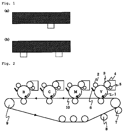
FIG. 1 is a configuration diagram schematically showing the fundamental configuration of an exemplary embodiment of the image forming apparatus of the invention; and
FIG. 2 is a configuration diagram schematically showing, the fundamental configuration of another exemplary embodiment of the image forming apparatus of the invention.
Detailed description
Carrier for Developing Electrostatic Latent Images
A carrier for developing an electrostatic latent image of the invention (hereinafter, may also be referred to as "carrier of the invention") includes carrier particles including magnetic particles and a coating layer coating the surfaces of the magnetic particles, in which the BET specific surface area of the magnetic particles is 0.1300 m.sup.2/g (or about 0.1300 m.sup.2/g) to 0.2500 m.sup.2/g (or about 0.2500 m.sup.2/g); and the difference in BET specific surface areas (hereinafter, sometimes referred to as "difference in BET specific surface areas according to the invention") obtained by subtracting the BET specific surface area of the magnetic particles from the BET specific surface area of the carrier particles is 0.0300 m.sup.2/g (or about 0.0300 m.sup.2/g) to 0.400 m.sup.2/g (or about 0.400 m.sup.2/g).
Furthermore, according to the invention, the BET specific surface area of the magnetic particles, and the BET specific surface area of the magnetic particles coated with a coating layer (carrier particles) are measured by a three-point method involving nitrogen purging, using a specific surface area measuring apparatus, SA3100 (trade name, manufactured by Beckman Coulter, Inc.). Specifically, the magnetic particles or the magnetic particles coated with a coating layer are introduced as a particle sample into a 5-gram cell, and deaeration is performed at 60.degree. C. for 120 minutes, followed by measurement using a mixed gas of nitrogen and helium (nitrogen:helium=30:70).
The BET specific surface area of the magnetic particles is typically 0.1300 m.sup.2/g to 0.2500 m.sup.2/g, preferably 0.1400 m.sup.2/g to 0.2200 m.sup.2/g, and more preferably 0.1500 m.sup.2/g to 0.2000 m.sup.2/g.
The difference in the BET specific surface areas between the magnetic particles and the carrier particles according to the invention is typically 0.0300 m.sup.2/g (or about 0.0300 m.sup.2/g) to 0.400 m.sup.2/g (or about 0.400 m.sup.2/g), preferably 0.0300 m.sup.2/g (or about 0.030 m.sup.2/g) to 0.1400 m.sup.2/g (or about 0.1400 m.sup.2/g), more preferably 0.0500 m.sup.2/g (or about 0.0500 m.sup.2/g) to 0.1300 m.sup.2/g (or about 0.1300 m.sup.2/g), and further more preferably 0.0700 m.sup.2/g (or about 0.0700 m.sup.2/g) to 0.1300 m.sup.2/g (or about 0.1300 m.sup.2/g). When the difference in the BET specific surface areas according to the invention falls in a range of from 0.0300 m.sup.2/g to 0.1400 m.sup.2/g, as a prominent effect thereof, a carrier in which less moisture adsorption occurs even under high temperature and high humidity conditions and which has a large amount of electrical charge may be obtained, regardless of the toner used in combination with the carrier.
When the difference in the BET specific surface areas according to the invention is larger than 0.1400 m.sup.2/g, moisture is adsorbed into pores of the carrier particles, resulting in low charging under high temperature and high humidity conditions, and thus, if low density images are output, color spots are generated.
When the carrier of the invention includes a colorant, to be described later, and is used in combination with toner particles having a shape factor of 100 (or about 100) to 130 (or about 130), a volume average particle size of 3.0 .mu.m (or about 3.0 .mu.m) to 6.5 .mu.m (or about 6.5 .mu.m), and a particle size distribution of microparticles of 1.30 or less (or about 1.30 or less), clear images with no image density unevenness may be obtained, when the difference in the BET specific surface areas according to the invention falls in a range of from 0.0300 m.sup.2/g to 0.4000 m.sup.2/g.
The carrier particles included in the carrier of the invention preferably have a volume average particle size of 20 .mu.m (or about 20 .mu.m) to 60 .mu.m (or about 60 .mu.m), more preferably 25 .mu.m (or about 25 .mu.m) to 55 .mu.m (or about 55 .mu.m), and further more preferably 30 .mu.m (or about 30 .mu.m) to 50 .mu.m (or about 50 .mu.m). When the volume average particle size of the carrier particles is larger than 60 .mu.m, the collision energy is increased inside a developing machine, and thus breaking or cracking of the carrier particles is accelerated. Also, the surface area for imparting electrical charge to the toner may be decreased, the function of imparting electrical charge to the toner may be deteriorated, and the image definition may be lowered. Meanwhile, when the volume average particle size of the carrier particles is smaller than 20 .mu.m, the magnetic force per unit entity is reduced, and thus, the magnetic binding power of continuous chains on the magnetic brush may be weakened to a level lower than that of an electric field for development, resulting in an increase in the migration of the carrier to the photoreceptor.
The volume average particle size of the carrier particles is measured as follows. First, 2 ml of a 5% aqueous solution of sodium alkylbenzenesulfonate is diluted with 100 ml of purified water, and 100 mg of a test sample is added to the diluted solution. The solution in which the sample is suspended is subjected to dispersion with an ultrasonic dispersing machine for 1 minute, and the particle size is measured using a laser diffraction/scattering type particle size distribution measuring apparatus (LS Particle Size Analyzer, trade name: LS13 320, manufactured by Beckman Coulter, Inc.), in water at a pump speed of 90%. The volume cumulative distribution curve is drawn from the smaller particle size side based on the counts for the respective segmented particle size ranges (channels) determined from the obtained particle size distribution, and the particle size at a cumulative value of 50% is represented by the volume average particle size, D.sub.50v, which is considered to be the volume average particle size of the carrier particles.
With regard to the carrier of the invention, the shape factor of the magnetic particles may be 100 (or about 100) to 130 (or about 130) (or preferably 100 (or about 100) to 120 (or about 120)), and the shape factor of the magnetic particles coated with a coating layer may be 100 (or about 100) to 130 (or about 130) (or preferably 100 (or about 100) to 120 (or about 120)). When the shape factors of the magnetic particles and of the magnetic particles coated with a coating layer exceed 130, the carrier particles collide with each other, and cracks may be generated in the salient parts thereof. A shape factor that is closer to 100 means that the shape of the particle is closer to a true sphere.
Here, the shape factor of the magnetic particles or the magnetic particles coated with a coating layer is represented by the following Expression (2). According to the invention, optical microscopic images of 50 or more magnetic particles or 50 or more magnetic particles coated with a coating layer at a magnification of 250 times, are captured into an image analyzer (registered trade name: LUZEX III, manufactured by Nireco Corporation), and from the maximum lengths and the projected areas of the particles, the values of shape factor for the individual particles are calculated and averaged. (ML.sup.2/A).times.(.pi./4).times.100 Expression
In Expression (2), ML represents the absolute maximum length of a particle, and A represents the projected area of a particle.
With regard to the carrier of the invention, the magnetic particles may satisfy the following Expression (1), and the coating layer may include a thermoplastic resin having an alicyclic group, in view of increasing the amount of electrical charge under high temperature and high humidity conditions and obtaining a clear image. 3.5.ltoreq.A/a.ltoreq.7.0 Expression
In Expression (1), A represents the BET specific surface area (unit: m.sup.2/g) of the magnetic particles, and "a" represents the sphere-equivalent specific surface area (unit: m.sup.2/g) of the magnetic particles, which is the specific surface area per unit weight assuming that the magnetic particles are perfectly smooth spheres.
The value of A/a is more preferably 4.0 to 6.5.
The sphere-equivalent specific surface area of the magnetic particles, which is represented by "a", may be represented by an expression: a=6/(d.times..rho.), in which d (unit: .mu.m) represents the volume average particle size of the magnetic particles, and .rho. (unit: dimensionless) represents the true specific gravity of the magnetic particles. Thus, the sphere-equivalent specific surface area of the magnetic particles is a specific surface area per unit weight assuming that the magnetic particles are perfectly smooth spheres, and thus may be deduced as follows.
The surface area of a single magnetic particle, S (m.sup.2), and the volume, V (m.sup.2), are represented by the following Expressions
and (4). S=4.pi..times.{(d/2).times.10.sup.-6}.sup.2 Expression
V=(4/3).times..pi..times.{(d/2).times.10.sup.-6}.sup.3 Expression
The density of the magnetic particles is represented by .rho..times.10.sup.6 (g/m.sup.3), and the weight M (g) of a single magnetic particle is represented by the following Expression (5). M=V.times..rho..times.10.sup.6=(1/6).pi..rho.d.sup.3.times.10.sup.-12 Expression
Thus, since the sphere-equivalent specific surface area, "a", is the surface area per unit weight as described above, "a" is deduced by the following Expression (6). a=S/M=6/(d.times..rho.) Expression
The true specific gravity .rho. of the magnetic particles is measured according to the method of measuring the density and specific gravity of a chemical product using a Le Chatelier type specific gravity bottle (known as JIS-K-0061, 5-2-1). The operation is performed as follows.
About 250 ml of ethyl alcohol is introduced into a Le Chatelier specific gravity bottle, and the meniscus is adjusted to be positioned at a scale mark.
The specific gravity bottle is immersed into a thermostatic water bath, and when the liquid temperature reaches 20.0.+-.0.2.degree. C., the position of the meniscus at a scale mark of the specific gravity bottle is accurately read (precision is 0.025 ml).
About 100 g of a sample is weighed, and the weight is designated as W (g).
The weighed sample is introduced into the specific gravity bottle, and bubbles are removed.
The specific gravity bottle is immersed into the thermostatic water bath, and when the liquid temperature reaches 20.0.+-.0.2.degree. C., the position of the meniscus is accurately read at a scale mark of the specific gravity bottle (precision is 0.025 ml).
The true specific gravity is calculated by the following expressions: D=W/(L2-L1) .rho.=D/0.9982 wherein D is the density of the sample (20.degree. C.) (g/cm.sup.3); .rho. is the true specific gravity of the sample (20.degree. C.); W is the apparent weight (g) of the sample; L1 is the reading of the meniscus (20.degree. C.) (ml) before the sample is introduced into the specific gravity bottle; L2 is the reading of the meniscus (20.degree. C.) (ml) after the sample is introduced into the specific gravity bottle; and 0.9982 is the density (g/cm.sup.3) of water at 20.degree. C.
The coating layer for the carrier of the invention preferably includes a resin with low polarity. Examples of the resin include a thermoplastic resin having an alicyclic group. The thermoplastic resin having an alicyclic group is not particularly limited as long as it has an alicyclic group and thermoplasticity, and may be selected depending on the purpose. The thermoplastic resin having an alicyclic group may be a homopolymer of a monomer having an alicyclic group, or may be a copolymer of a monomer having an alicyclic group and one or more additional monomers, as long as the resin obtained as a result of polymerization exhibits thermoplasticity.
Specific examples of the monomer having an alicyclic group include: alicyclic group-containing acrylic monomers such as cyclopropyl acrylate, cyclobutyl acrylate, cyclopentyl acrylate, cyclohexyl acrylate, cyclopropyl methacrylate, cyclobutyl methacrylate, cyclopentyl methacrylate, cyclohexyl methacrylate, or derivatives thereof; monomers that constitute norbornene resins; monomers that constitute polycarbonate resins; monomers that constitute polyester resins each having an alicyclic group; cyclohexanedimethanol; cyclohexanedicarboxylic acid; and biphenyl Z. Among them, the alicyclic group-containing acrylic monomers are preferred, and of them, cyclohexyl methacrylate is particularly preferred because it has a stable molecular structure.
Specific examples of the one or more additional monomers include monomers that constitute known resins, such as: nitrogen-containing acrylic monomers including amino group-containing acrylic monomers such as dimethylaminoethyl methacrylate, methylaminoethyl methacrylate, or dimethylaminobutyl methacrylate, and derivatives thereof; acrylic monomers other than those; monomers that constitute olefin resins such as polyethylene or polypropylene; monomers that constitute polyvinyl resins or polyvinylidene resins such as polystyrene resins, polyvinyl alcohol, polyvinyl butyral, polyvinyl chloride, polyvinyl carbazole, polyvinyl ether, or polyvinyl ketone; monomers that constitute straight silicone resins formed from organosiloxane bonds or modified products thereof; monomers that constitute fluorinated resins such as polytetrafluoroethylene, polyvinyl fluoride, polyvinylidene fluoride, or polychlorotrifluoroethylene; monomers that constitute amino resins such as polyurethane resins, phenol resins, urea-formaldehyde resins (urea resins), melamine resins, benzoguanamine resins, or polyamide resins; and monomers that constitute epoxy resins. Among these, nitrogen-containing acrylic monomers are preferable because it is easy for the carrier to hold electrical charges, and of those, the amino group-containing acrylic monomers are preferable, with dimethylamino methacrylate being even more preferable.
The ratio of copolymerization (weight ratio) when synthesizing a copolymer of a monomer having an alicyclic group and one or more additional monomers, that is, the monomer having an alicyclic group: one or more additional monomers, is preferably from 99.5:0.5 (or about 99.5:0.5) to 60:40 (or about 60:40), and is more preferably from 99:1 (or about 99:1) to 80:20 (or about 80:20).
When the proportion of the monomer having an alicyclic group is too large relative to the proportion of the one or more additional monomers so that the ratio is out of the aforementioned range, the coating with the resin is deteriorated due to steric hindrance among the alicyclic groups, or the like, and the resin may peel off from the surface of the carrier particles. When the proportion of the monomer having an alicyclic group is too small relative to the proportion of the one or more additional monomers so that the ratio is out of the aforementioned range, the resin may have poor environmental stability.
Furthermore, as for the resin for coating, a resin mixture of a resin synthesized using a monomer having an alicyclic group (a polymer synthesized using only the monomer having an alicyclic group, and/or a copolymer of the monomer having an alicyclic group and one or more additional monomers) and a resin synthesized without using a monomer having an alicyclic group may be used. In this case, the proportion of the resin synthesized using the monomer having an alicyclic group to the resin mixture is preferably 20% by weight or more, and more preferably 30% by weight or more. A proportion closer to 100% by weight is even more preferable. When the proportion of the resin synthesized using the monomer having an alicyclic group in the resin mixture accounts less than 20% by weight, the hydrophobicity at the surface of the carrier particles is decreased because the number of alicyclic groups included in the resin for coating is too small, and the environmental dependency of the resin on changes in temperature or humidity may be increased.
The combination of the monomers in the copolymer is not particularly limited. However, a combination of cyclohexyl methacrylate and a nitrogen-containing acrylic monomer is preferable, and a combination of cyclohexyl methacrylate and dimethylaminoethyl methacrylate is more preferable. These combinations allow an increase in the adhesiveness of the coating layer to the core material, and may enhance the electrical charging ability while suppressing the environmental dependency. In addition, a copolymer including cyclohexyl methacrylate and a nitrogen-containing acrylic monomer as the monomer components may be prevented from penetrating into the inside of the core material when the specific core material is applied, and the environmental dependency may thus be further improved.
With regard to the ratio of polymerization for the copolymer of cyclohexyl methacrylate and a nitrogen-containing acrylic monomer (particularly, dimethylaminoethyl methacrylate), the content (molar ratio) of the nitrogen-containing acrylic monomer with respect to the total content of the monomers used in the polymerization of the copolymer may be 0.5% by mole to 10% by mole.
The coating layer may include, if necessary, an electroconductive powder for the purpose of controlling the resistance or the like.
Specific examples of the electroconductive powder include: particles of a metal such as gold, silver, or copper; carbon black; Ketjen black; acetylene black; particles of a semi-conductive oxide having a volume resistivity of 10.sup.8 .OMEGA.cm to 10.sup.12 .OMEGA.cm, such as titanium oxide or zinc oxide; and particles prepared by coating the surface of the particles of titanium oxide, zinc oxide, barium sulfate, aluminum borate, or potassium titanate with tin oxide, carbon black, a metal, or the like. One of them may be used alone, or two or more thereof may be used in combination.
Furthermore, the volume resistivity as used in the invention is the value obtained at 20.degree. C. and 50% RH.
The electroconductive powder is preferably carbon black particles, for being favorable in terms of production stability, costs, electroconductivity or the like.
The type of the carbon black is not particularly limited, but the carbon black may have a DBP oil absorption of 50 ml/100 g to 250 ml/100 g due to its excellent production stability.
The volume average particle size of the electroconductive powder is preferably 0.5 .mu.m or less (or about 0.5 .mu.m or less), more preferably in a range of from 0.05 .mu.m (or about 0.05 .mu.m) to 0.5 .mu.m (or about 0.5 .mu.m), and further more preferably in a range of from 0.05 .mu.m (or about 0.05 .mu.m) to 0.35 .mu.m (or about 0.35 .mu.m). When the volume average particle size is smaller than 0.05 .mu.m, the aggregation property of the electroconductive powder is deteriorated, and the carrier particles tend to have different volume resistivities among them. When the volume average particle size is larger than 0.5 .mu.m, the electroconductive powder may easily fall off from the coating layer, and stable electrical charging ability may not be attained.
The volume average particle size of the electroconductive powder is measured using a laser diffraction type particle size distribution measuring apparatus (trade name: LA-700, manufactured by Horiba, Ltd.).
The measurement is performed as follows. First, 2 g of a test sample is added to 50 ml of a 5% aqueous solution of a surfactant, preferably sodium alkylbenzenesulfonate, and the mixture is subjected to dispersion for 2 minutes with an ultrasonic dispersing machine (1,000 Hz). A sample is thus prepared and is subjected to measurement.
The counts for the respective channels weighted by the particle volume corresponding to the respective channels are accumulated from the smaller volume average particle size side, and the particle size at which the cumulative counts reach 50% of the total counts is taken as the volume average particle size.
The volume resistivity of the electroconductive powder is preferably 10.sup.1 .OMEGA.cm (or about 10.sup.1 .OMEGA.cm) to 10.sup.11 .OMEGA.cm (or about 10.sup.11 .OMEGA.cm), and more preferably 10.sup.3 .OMEGA.cm (or about 10.sup.3 .OMEGA.cm) to 10.sup.9 .OMEGA.cm (or about 10.sup.9 .OMEGA.cm).
The volume resistivity of the electroconductive powder is measured in the same manner as that for the volume resistivity of the core material.
The amount of the electroconductive powder is preferably 0.05% by weight to 1.5% by weight, and more preferably 0.10% by weight to 1.0% by weight with respect to the total amount of the coating layer. When the amount of the electroconductive powder is larger than 1.5% by weight, a decrease in the resistance of the carrier occurs, and defects in the images may occur due to attachment of the carrier to developed images, or the like. On the other hand, when the amount of the electroconductive powder is smaller than 0.05% by weight, the carrier is insulated, and it may be difficult for the carrier to function as a development electrode during the development. In particular, when forming a solid black image, edge effects may occur, and thus the reproducibility of solid images may be deteriorated.
Furthermore, the coating layer may further include resin particles. Examples of the resin particles include thermoplastic resin particles and thermosetting resin particles. Among these, the thermosetting resin particles are preferred from the viewpoint that the hardness thereof is relatively easily increased, and resin particles formed from a nitrogen-containing resin including a nitrogen (N) atom are preferred from the viewpoint of imparting negative electrical charging ability to the toner. In addition, one of these resin particles may be used alone, or two or more thereof may be used in combination.
The volume average particle size of the resin particles is, for example, preferably 0.1 .mu.m to 2.0 .mu.m, and more preferably 0.2 .mu.m to 1.0 .mu.m. When the volume average particle size of the resin particles is less than 0.1 .mu.m, the dispersibility of the resin particles in the coating layer may be extremely poor. When the volume average particle size of the resin particles exceeds 2.0 .mu.m, the resin particles may easily fall off from the coating layer, and the originally intended effects may not be exhibited.
The volume average particle size of the resin particles is determined by a measurement method substantially similar to that for the volume average particle size of the electroconductive powder.
The amount of the resin particles is preferably 1% by volume to 50% by volume, more preferably 1% by volume to 30% by volume, and further more preferably 1% by volume to 20% by volume with respect to the total coating layer. When the amount of the resin particles is smaller than 1% by volume, the effects due to the resin particles may not be exhibited. When the amount of the resin particles exceeds 50% by volume, the resin particles may easily fall off from the coating layer, and stable electrical charging ability may not be obtained.
The total amount of the coating layer in the carrier of the invention is preferably in a range of from 0.5 parts by weight to 10 parts by weight, more preferably 1 part by weight to 5 parts by weight, and particularly preferably 1 part by weight to 3 parts by weight with respect to 100 parts by weight of the magnetic particles. When the amount of the coating layer is smaller than 0.5 parts by weight, the extent of surface exposure of the magnetic particles is excessive, and thus the magnetic particles tend to be under the charging influence of the development electric field. Meanwhile, when the amount of the resin layer is larger than 10 parts by weight, the amount of resin powder that detaches from the coating layer increases, and the developer may include detached carrier resin powder from an early stage.
The coating ratio of the coating layer at the surface of the magnetic particles is preferably 80% or higher, more preferably 85% or higher, and further more preferably substantially 100%. When the coating ratio is less than 80%, if the carrier has been used for a long time, the resistance of the carrier is lowered due to peeling off or the like of the coating resin, and as a result, injection of charge to the carrier occurs. Thus, there are cases where a carrier which has been charge-injected migrates to the photoreceptor, and causes decoloration of images.
The coating ratio of the coating layer is obtained by X-ray photoelectron spectroscopy (XPS) measurement. The measurement is performed with an XPS measuring apparatus JPS80 (trade name, manufactured by JEOL, Ltd.) using a MgK.alpha. ray as an X-ray source under the conditions of an acceleration voltage of 10 kV and an emission current of 20 mV. The measurement is conducted on the main element(s) constituting the coating layer (usually carbon), and the main element(s) constituting the magnetic particles (for example, iron and oxygen in the case where the magnetic particles include an iron oxide material such as magnetite). Hereinafter, description will be given assuming that the magnetic particles include iron oxide. Here, a C1s spectrum is measured for the measurement of carbon, an Fe2p3/2 spectrum is measured for the measurement of iron, and an O1s spectrum is measured for the measurement of oxygen.
The respective numbers of atoms of carbon (A.sub.C), oxygen (A.sub.O) and iron (A.sub.Fe) are determined on the basis of the respective spectra of these elements. From the ratio of the numbers of the atoms of carbon, oxygen and iron thus obtained, the ratios of iron content in a single magnetic particle and in a single magnetic particle coated with a coating layer (carrier) are determined by the following expression (I). Subsequently, the coating ratio is determined by the following expression (II). Ratio of iron content(atomic %)=A.sub.Fe/(A.sub.C+A.sub.O+A.sub.Fe).times.100 Expression (I) Coating ratio(%)={1-(ratio of iron content in carrier)/(ratio of iron content in magnetic particle)}.times.100 Expression (II)
The average film thickness of the respective coating layers is preferably 0.1 .mu.m to 10 .mu.m, more preferably 0.1 .mu.m to 3.0 .mu.m, and particularly preferably 0.1 .mu.m to 1.5 .mu.m. When the average film thickness of the coating layers is thinner than 0.1 .mu.m, there may be a decrease in the resistance due to the peeling off of the coating layer when the carrier is used for a long period of time, and it may become difficult to sufficiently control the pulverization of the carrier. On the other hand, when the average film thickness of the coating layer exceeds 10 .mu.m, it may take a long time to reach charge saturation.
The average film thickness (.mu.m) of the coating layer may be obtained as described below, when the true specific gravity of the magnetic particles is designated as .rho. (dimensionless), the volume average particle size of the magnetic particles is designated as d (.mu.m), the average specific gravity of the coating layer is designated as .rho..sub.C, and the total amount of the coating layer with respect to 100 parts by weight of the magnetic particles is designated as W.sub.C (parts by weight). Average film thickness(.mu.m)=[Amount of coating resin(including all additives such as electroconductive agents) per one carrier particle/Surface area per one carrier particle]/Average specific gravity of coating layer=[4/3.pi.(d/2).sup.3.rho.W.sub.C]/[4.pi.(d/2).sup.2]/.rho..sub.C=(1/- 6)(d.rho.W.sub.C/.rho..sub.C)
The magnetic particles in the carrier of the invention are not particularly limited as long as they satisfy the conditions described above. Examples of the materials for the magnetic particles include: magnetic metals such as iron, steel, nickel or cobalt; magnetic oxides such as ferrite and magnetite; and glass beads. In particular, ferrite particles are used as the magnetic particles in exemplary embodiments of the invention, because they may easily provided with uniform surfaces and stable electrical charging properties.
The magnetic particles are formed by granulation and sintering. The particles may be finely pulverized as a pretreatment. The pulverization method is not particularly limited, and pulverization may be conducted according to known pulverization methods. Specific examples thereof include methods using a mortar, a ball mill, a jet mill or the like. The final state of pulverization in the pretreatment may vary depending on the material of the particles or the like. However, the volume average particle size of the particles may be 2 .mu.m to 10 .mu.m. When the volume average particle size is less than 2 .mu.m, the desired particle size may not be obtained. When the volume average particle size exceeds 10 .mu.m, the particle size may be excessively large, or the degree of circularity may be small.
The sintering temperature is preferably adjusted to be lower than those used in conventional sintering. Specifically, although the sintering temperature may vary depending on the material to be used, the temperature is preferably 500.degree. C. to 1,200.degree. C., and more preferably 600.degree. C. to 1,000.degree. C. When the sintering temperature is lower than 500.degree. C., the magnetic force necessary for the carrier may not be obtained. When the sintering temperature exceeds 1,200.degree. C., crystals grow rapidly, and the internal structure may tend to be non-uniform, resulting in possibility of cracks and chips.
In order to keep the sintering temperature low, preliminary sintering in the sintering process may be performed in a stepwise manner. Therefore, the entire sintering process may take a sufficiently long period of time.
Regarding the magnetic force of the magnetic particles, a saturation magnetization of the magnetic particles is preferably 50 emu/g or greater, and more preferably 60 emu/g or greater, in a field of 1,000 Oersted. When the saturation magnetization is lower than 50 emu/g, the carrier may be developed on the photoreceptor, together with the toner.
For the measurement of magnetic characteristics, a vibrating sample magnetometer, VSMP10-15 (trade name, manufactured by Toei Industry Co., Ltd.) is used. The test sample is packed in a cell having an internal diameter of 7 mm and a height of 5 mm, and the cell is mounted on the apparatus. A magnetic field is applied to the test sample, and the magnetic field is swept to a maximum of 1,000 Oersted. Subsequently, the applied magnetic field is reduced, and a hysteresis curve is plotted on a recording paper. By using the curve data, the saturation magnetization, the residual magnetization, and the retention force are determined. In exemplary embodiments of the invention, the saturation magnetization represents the magnetization value measured in a magnetic field of 1,000 Oersted.
The volume resistivity of the magnetic particles is preferably in a range of from 10.sup.5 .OMEGA.cm to 10.sup.9.5 .OMEGA.cm, and more preferably in a range of from 10.sup.7 .OMEGA.cm to 10.sup.9 .OMEGA.cm. When the volume resistivity is smaller than 10.sup.5 .OMEGA.cm, when the toner concentration in the developer is decreased because of repeated copying, charge injection occurs to the carrier, and the carrier itself may be developed. On the other hand, when the volume resistivity is greater than 10.sup.9.5 .OMEGA.cm, the image quality may be adversely influenced by a significant edge effect, pseudo-contours, or the like.
The volume resistivity (.OMEGA.cm) of the magnetic particles is measured in the following manner. In this case, the measurement is performed under a temperature of 20.degree. C. and a humidity of 50% RH.
On the surface of a circular jig on which a 20-cm.sup.2 electrode plate is disposed, an object of measurement is mounted linearly to form a layer having a thickness of about 1 to 3 mm. Another 20-cm.sup.2 electrode plate is mounted thereon so that the layer is interposed between the electrode plates. In order to eliminate any spaces among the particles of the object of measurement, a load of 4 kg is placed on the electrode plate mounted on the layer, and the thickness (cm) of the layer is then measured. The electrodes on and under the layer are respectively connected to an electrometer and a high voltage power supply device. A high voltage is applied to the electrodes to generate an electric field of 10.sup.3.8 V/cm, and the current value (A) flowing at this time point is read. Subsequently, the volume resistivity (.OMEGA.cm) of the object of measurement is calculated. The expression for calculation of the volume resistivity (.OMEGA.cm) of the object of measurement is as follows. R=E.times.20/(I-I.sub.0)/L Expression
In the expression, R represents the volume resistivity (.OMEGA.cm) of the object of measurement, E represents the applied voltage (V), I represents the current value (A), I.sub.0 represents the current value (A) at an applied voltage of 0 V, and L represents the thickness (cm) of the layer. The coefficient of 20 represents the area (cm.sup.2) of each of the electrode plates.
With regard to the carrier of the invention, as a method of controlling the difference in the BET specific surface areas according to the invention to fall in a range of from 0.0300 m.sup.2/g to 0.400 m.sup.2/g, there is a method of reducing the burden to the carrier during production by using, as the resin used in the coating layer, a copolymer of a monomer having a polar group and a monomer not having a polar group. Specifically, when a carrier is produced using a kneader, the difference in the BET specific surface area may be controlled to fall within the above-described range, by stirring the material at a low speed under substantially vacuum conditions.
Developer for Electrostatic Latent Image Development
The developer for electrostatic latent image development of the invention (hereinafter, sometimes referred to as "developer of the invention") includes at least a toner including toner particles, and the carrier particles for developing an electrostatic latent image of the invention.
The toner used in the invention is not particularly limited as long as it is a toner including a colorant, and any known toner may be used. For example, a colored toner including a binding resin and a colorant may be used. It is possible to use a toner including a colorant, and having a shape factor of 100 (or about 100) to 130 (or about 130), a volume average particle size of 3.0 .mu.m (or about 3.0 .mu.m) to 6.5 .mu.m (or about 6.5 .mu.m), and a particle size distribution on the fine particles side of 1.30 or less (or about 1.30 or less).
When the toner, which includes a colorant, and has a shape factor of 100 to 130, a volume average particle size of 3.0 .mu.m to 6.5 .mu.m, and a particle size distribution on the fine particles side of 1.30 or less (hereinafter, sometimes referred to as "specific toner"), is used in combination with the carrier of the invention as described above, the charging ability is not decreased, clear images are obtained even at low image densities, and at the same time, unevenness in concentration may be prevented even under low temperature and low humidity conditions.
First, the specific toner will be described.
The shape factor of the specific toner is typically 100 to 130, and preferably 100 to 125. When the shape factor of the specific toner exceeds 130, the contact area between the toner and the carrier increases, and thus unevenness in concentration may occur. Particularly, since the toner concentration in the developer increases under low temperature and low humidity conditions, this phenomenon may become more prominent.
When toner particles having a shape factor of 130 or more (or about 130 or more) are included in addition to the specific toner, the ratio thereof is preferably 10% or less (or about 10% or less), and more preferably 5% or less (or about 5% or less) with respect to the total number of toner particles. When the ratio of the particles having a shape factor of 130 or more exceeds 10%, the toner may remain on the photoreceptor, resulting in deterioration of the transfer rate.
According to the invention, the shape factor of the toner is determined by the following expression: Shape factor=100.pi..times.(ML).sup.2/(4.times.A) wherein ML represents the maximum length of the toner particles, and A is the surface area of the toner particles. The shape factor of the toner may be calculated in the following manner. An optical microscopic image of a toner dispersed on a glass slide is captured into an image analyzer (registered trade name: LUZEX III, manufactured by Nireco Corporation) through a video camera, then the maximum lengths and projected areas of 100 or more toner particles are respectively determined, the shape factor of each particle is obtained by the above expression, and the average value thereof is then determined.
The description continues in the full USPTO document.
 Lapsed, fee not paid2 drawings

