Statement regarding federally sponsored research or development
Not applicable.
Background and field of the invention
The present invention generally relates to carbon nanotubes (CNTs), and more specifically to CNTs incorporated in composite materials.
Carbon nanotubes (CNTs") exhibit roughly eighty times the strength, six times the toughness, as indicated by Young's Modulus, and one-sixth the density of high carbon steel. Due to these favorable mechanical properties, CNTs have been used as a reinforcing element in composite materials. CNT-based composites can be less dense than many metals, while providing improved strength and corrosion protection. CNTs also exhibit favorable properties for thermal and electrical applications as well.
Most processes for producing CNT-based composites involve direct mixing of loose CNTs or bundled CNT-based yarns into the matrix material of the nascent composite. When employing CNTs in this manner in a typical resin-type matrix material, the resultant composites are typically limited to a maximum of about three weight percent of carbon nanotubes in the finished composite material. The reason for this limitation is the resulting increased viscosity of the matrix and a decreased ability to impregnate the resulting composite.
CNTs have also been employed in hybrid composites in which two, three, or more different reinforcing elements are incorporated within a composite. Hybrid composite systems which incorporate nanoscale reinforcements require additional processing steps to properly disperse the nanoparticles, including CNTs. CNT incorporation into a matrix has the added challenge of controlling CNT orientation which adds to the processing complexity. Moreover, limitations on CNT loading due to various factors, such as large viscosity increases have been observed in hybrid composite systems as well.
Hybrid composite manufacturing processes become increasingly complex if variable CNT loading or different CNT types are needed in different portions of a composite structure. It would be beneficial to decrease the complexity of manufacture of CNT composites and tailored hybrid composites and to provide composite articles with improved CNT loading capacity while also controlling CNT orientation. The present invention satisfies these needs and provides related advantages as well.
Summary of the invention
In some aspects, embodiments disclosed herein relate to a composite composition that includes a plurality of carbon nanotube (CNT)-infused fibers dispersed in a matrix material. The amount of carbon nanotubes in the composition is in a range between about 0.1% percent by weight to about 60 percent by weight of the composite.
Brief description of the drawings
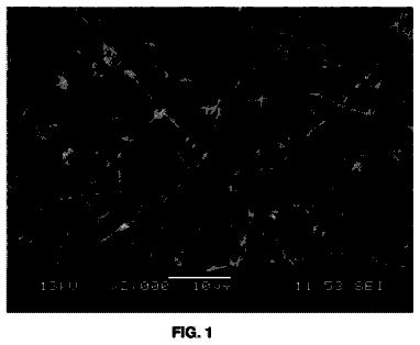
FIG. 1 shows a transmission electron microscope (TEM) image of a multi-walled CNT (MWNT) grown on AS4 carbon fiber via a continuous CVD process.
FIG. 2 shows a TEM image of a double-walled CNT (DWNT) grown on AS4 carbon fiber via a continuous CVD process.
FIG. 3 shows a scanning electron microscope (SEM) image of CNTs growing from within the barrier coating where the CNT-forming nanoparticle catalyst was mechanically infused to the carbon fiber material surface.
FIG. 4 shows a SEM image demonstrating the consistency in length distribution of CNTs grown on a carbon fiber material to within 20% of a targeted length of about 40 microns.
FIG. 5 shows an SEM image demonstrating the effect of a barrier coating on CNT growth. Dense, well aligned CNTs grew where barrier coating was applied and no CNTs grew where barrier coating was absent.
FIG. 6 shows a low magnification SEM of CNTs on carbon fiber demonstrating the uniformity of CNT density across the fibers within about 10%.
FIG. 7 shows a process for producing CNT-infused carbon fiber material in accordance with the illustrative embodiment of the present invention.
FIG. 8 shows how a carbon fiber material can be infused with CNTs in a continuous process to target thermal and electrical conductivity improvements.
FIG. 9 shows how carbon fiber material can be infused with CNTs in a continuous process using a "reverse" barrier coating process to target improvements in mechanical properties, especially interfacial characteristics such as shear strength.
FIG. 10 shows how carbon fiber material can be infused with CNTs in another continuous process using a "hybrid" barrier coating to target improvements in mechanical properties, especially interfacial characteristics such as shear strength and interlaminar fracture toughness.
FIG. 11 shows the effect of infused CNTs on IM7 carbon fiber on interlaminar fracture toughness. The baseline material is an unsized IM7 carbon fiber, while the CNT-Infused material is an unsized carbon fiber with 15 micron long CNTs infused on the fiber surface.
FIG. 12 shows a tailored fiber-reinforced composite structure utilizing two types of CNT-infused fibers in different portions of the composite structure. The top lamina shows CNTs of a relatively shorter length than the CNTs of the lower lamina.
FIG. 13 shows a tailored fiber-reinforced composite structure utilizing two types of CNT-infused fibers in different portions of the composite structure. The top lamina shows CNTs generally perpendicular to the fiber axis while the lower lamina shows CNTs generally parallel to the fiber axis.
FIG. 14 shows tailored fiber-reinforced composite structure utilizing two types of CNT-infused fibers in different portions of the composite structure. The top lamina shows CNTs of a relatively lower density than the CNTs of the lower lamina.
FIG. 15 shows tailored fiber-reinforced composite structure utilizing CNT-infused fiber orientations in different portions of the composite structure. The top-most lamina shows CNT-infused fibers parallel to the cross section while the alternate layer beneath shows CNT-infused fibers perpendicular to cross section.
Detailed description of the invention
The present invention is directed, in part, to composite materials that include a matrix material and carbon nanotube (CNT)-infused fiber materials. The inclusion of CNT-functionalized fiber materials in a composite allows larger CNT loadings in matrix materials which have previously been limited by increases in viscosity with increased CNT loading. The larger possible CNT loading, coupled with a high degree of control over relative CNT orientation, increases the impact of CNT properties imparted to the overall composite material. The control over how the CNT-infused fiber material is disposed within the composite matrix material provides access to sophisticated hybrid composite materials that are readily tailored to specific target needs, such as improved mechanical, electrical, and thermal properties.
CNT orientation in the composite is controlled, in part, by the fiber material scaffold onto which the CNTs are infused. As described further below, there are two basic orientations of the infused CNTs relative to the axes of individual fiber of the fiber material. In some embodiments, the CNTs are displayed radially about the fiber axes. In such embodiments, the CNTs are grown generally perpendicularly from the fiber axes. In other embodiments, the CNT-infused fiber undergoes further treatment to orient the CNTs generally parallel to the fiber axis. These fixed orientations of the CNTs on the fiber material lead to predictable orientations of the CNTs in the overall composite structure.
The composite structures of the invention can also incorporate CNT-infused fiber materials having different CNT types in different portions of the overall composite. For example, shorter CNTs can be incorporated into portions of a composite structure to enhance mechanical properties. CNTs with longer lengths can be incorporated into other portions of the same composite structure to enhance electrical or thermal properties. The incorporation of different types of CNT-infused fiber materials in a composite structure is exemplified in FIG. 12. FIG. 12 show composite structure 1200 which includes a matrix material 1210 and CNT-infused fiber material 1220. In this exemplary structure, a first layer 1230 of composite structure 1200 has CNTs of short length which can be effective in providing mechanical strength to this portion of composite structure 1200. A second layer 1240 incorporates CNT-infused fiber materials having relatively longer CNT lengths. As shown in the figure, the CNT can be of sufficient length to generate percolation pathways which can be useful to realize beneficial electrical and/or thermal conductivity properties in second layer 1240 of composite structure 1200. In some embodiments, the composite structures of the invention can also include sections of fiber material reinforcement that are devoid of any infused CNTs.
Fiber reinforced composite structures of the present invention are useful because their properties can be tailored to fulfill a given set of requirements as exemplified in FIG. 12. As a further example, a particular lamina stacking sequence can be used to optimize a composite beam for flexural stiffness or another sequence can be used to optimize for torsional rigidity. Hybrid composites, which utilize two or more different types of reinforcement fiber, benefit from the positive contributions of each fiber towards overall composite properties, whether they are mechanical, thermal or electrical.
Composite structures made by processes disclosed herein, with CNT infused fibers, have shown increased mechanical properties, including in shear--interlaminar and in-plane. Additionally these composite structures have improved electrical and thermal conductivity, based, in part, on good CNT loading and control of CNT orientation. The CNT infused fibers disclosed herein can be used in composite structures in various orientations and locations to provide custom tailored properties, including properties not available to current fiber-reinforced composite materials. For example, processes of the invention can produce a composite structure to handle high shear loading in the central planes, but is electrically insulated across the thickness. CNT-infused fibers can be used for the central lamina of a tailored composite to improve the maximum shear strength characteristics. Unmodified glass fibers can be used in surface layers to provide the electrical insulation properties.
In still further exemplary embodiments, tailored composites can utilize the improved electrical properties of the CNT-infused fibers in a variety of contexts. For example, a composite wing subjected to icy conditions can have some layers made with CNT-infused fibers, such that a large circuit is created when an electrical potential is applied. This layer acts as a large resistive heater to heat, remove, or prevent icy conditions. This avoids the need for external heating and the composite retains homogeneity because only two types of fiber are being used. A second fiber type (or the same fiber type) with different CNT types can be employed within the same composite to provide additional strength, without increasing processing steps in the composite manufacture. The compatibility between the CNT-infused fibers and any unmodified fibers reduces the possibility of critical defects forming during the layup of the composite based on mismatches in coefficient of thermal expansion, size and stiffness variations of other heating elements.
Similarly, a composite component can be designed to handle a variety of loadings. For example, one component can have a joint which carries a shear load while another portion supports a compressive load. The portion subject to shear and susceptible to delamination failure can be made with CNT-infused fibers with a high loading of CNTs for increased shear stiffening effect. The portion of the part supporting a tensile load can utilize fibers with a lower CNT coverage to provide a higher strength based on the associated higher fiber volume. The control of the CNT infusion on the fiber is readily tailored prior to composite formation, simplifying the composite production process.
Furthermore, the CNT-infused fibers described herein can be produced in a continuous fashion with precise control of the CNT loading, CNT length, and CNT orientation. Other hybrid composite systems which incorporate nanoscale reinforcement require additional processing steps to properly disperse the nanoparticles of nanotubes into the matrix. By having the CNTs infused to a fiber material as a carrier, distribution, orientation and types of the CNTs are controlled. Methods of the present invention also allow the user to create a lamina with specific CNT loading, different from a next layer as controlled by the CNT-infusion process, described herein below.
The CNT-infused fibers can be incorporated into a composite using the same manufacturing techniques used for un-processed glass and carbon filaments, for example, without the need for extra processing steps including orienting the CNTs or sectional layering in multilayered composites. Moreover, because the CNTs are infused to a fiber carrier, the issues associated homogeneous incorporation of CNTs, CNT bundling, and the like, are alleviated. CNT-infused fibers allow resin-based composite structures to have larger CNT loading than can be achieved by simply mixing CNTs directly with the composite matrix material.
In currently manufactured composites, it is typical to have a 60% fiber material to 40% matrix volume ratio, however the introduction of a third element, that is the infused CNTs on the fiber material, allows these ratios to be altered. For example, with the addition of up to about 25% CNTs by volume, the fiber portion can vary between about 10% to about 75% with the matrix range changing to between about 15% to about 85%. The various ratios can alter the properties of the overall composite, which can be tailored to target one or more desired characteristics. The properties of CNTs lend themselves to fiber materials that are reinforced with them. Utilizing these enhanced fibers in tailored composites similarly imparts increases that will vary according to the fiber fraction, but can still greatly alter the properties of tailored composites compared to those know in the art.
As used herein the term "fiber material" refers to any material which has a fiber or filament as its elementary structural component. Fiber is a unit of matter, either natural, or manufactured, which forms the basic element of fabrics and other textile structures. Filament is a single fiber of an indefinite length, either natural or manufactured. As used herein, the terms "fiber" and "filament" can be used interchangeably. The term "fiber material" encompasses fibers, filaments, yarns, tows, tapes, ribbons, woven and non-woven fabrics, plies, mats, 3D woven structures, and the like.
As used herein the term "spoolable dimensions" refers to fiber materials having at least one dimension that is not limited in length, allowing for the material to be stored on a spool or mandrel. Fiber materials of "spoolable dimensions" have at least one dimension that indicates the use of either batch or continuous processing for CNT infusion as described herein. An exemplary fiber material of spoolable dimensions that is commercially available is exemplified by AS4 12 k carbon fiber tow with a tex value of 800 (1 tex=1 g/1,000 m) or 620 yard/lb (Grafil, Inc., Sacramento, Calif.). Commercial carbon fiber tow, in particular, can be obtained in 5, 10, 20, 50, and 100 lb. (for spools having high weight, usually a 3 k/12K tow) spools, for example, although larger spools may require special order. Processes of the invention operate readily with 5 to 20 lb. spools, although larger spools are usable. Moreover, a pre-process operation can be incorporated that divides very large spoolable lengths, for example 100 lb. or more, into easy to handle dimensions, such as two 50 lb spools. Similarly spoolable lengths of glass, ceramic, metal, and organic fiber materials, such as aramid fiber materials, are readily available and known to those of skill in the art. As described above any fiber material can be supplied in the form of tows, rovings, fabrics, and the like.
As used herein, the term "carbon nanotube" (CNT, plural CNTs) refers to any of a number of cylindrically-shaped allotropes of carbon of the fullerene family including single-walled carbon nanotubes (SWNTs), double-walled carbon nanotubes (DWNTs), multi-walled carbon nanotubes (MWNTs). CNTs can be capped by a fullerene-like structure or open-ended. CNTs include those that encapsulate other materials. CNTs also include those that result from various functionalization chemistry, as known in the art. Examples include, without limitation, CNT fluorination and oxidation with oxidizing acids such as nitric acid. Such functionalization chemistry is performed after growth of the CNTs on the fiber material. One skilled in the art will recognize the compatibility of any functionalization chemistry with the fiber material itself.
As used herein "uniform in length" refers to length of CNTs grown on a fiber material in a reactor. "Uniform length" means that the CNTs have lengths with tolerances of plus or minus about 20% of the total CNT length or less, for CNT lengths varying from between about 1 micron to about 500 microns. At very short lengths, such as 1-4 microns, this error may be in a range from between about plus or minus 20% of the total CNT length up to about plus or minus 1 micron, that is, somewhat more than about 20% of the total CNT length.
As used herein "uniform in distribution" refers to the consistency of density of CNTs on a fiber material. "Uniform distribution" means that the CNTs have a density on the fiber material with tolerances of plus or minus about 10% coverage defined as the percentage of the surface area of the fiber covered by CNTs. This is equivalent to .+-.1500 CNTs/.mu.m.sup.2 for an 8 nm diameter CNT with 5 walls. Such a figure assumes the space inside the CNTs as finable.
As used herein, the term "infused" means bonded and "infusion" means the process of bonding. Such bonding can involve direct covalent bonding, ionic bonding, pi-pi, and/or van der Waals force-mediated physisorption. For example, in some embodiments, the CNTs can be directly bonded to the carbon fiber material. Bonding can be indirect, such as the CNT infusion to the fiber material via a barrier coating and/or an intervening transition metal nanoparticle disposed between the CNTs and carbon fiber material. In the CNT-infused fiber materials disclosed herein, the carbon nanotubes can be "infused" to the fiber material directly or indirectly as described above. The particular manner in which a CNT is "infused" to a fiber materials is referred to as a "bonding motif."
As used herein, the term "transition metal" refers to any element or alloy of elements in the d-block of the periodic table. The term "transition metal" also includes salt forms of the base transition metal element such as oxides, carbides, nitrides, and the like.
As used herein, the term "nanoparticle" or NP (plural NPs), or grammatical equivalents thereof refers to particles sized between about 0.1 to about 100 nanometers in equivalent spherical diameter, although the NPs need not be spherical in shape. Transition metal NPs, in particular, serve as catalysts for CNT growth on the fiber materials.
As used herein, the term "sizing agent," "fiber sizing agent," or just "sizing," refers collectively to materials used in the manufacture of fibers as a coating to protect the integrity of fibers, provide enhanced interfacial interactions between a fiber and a matrix material in a composite, and/or alter and/or enhance particular physical properties of a fiber. In some embodiments, CNTs infused to fiber materials behave as a sizing agent.
As used herein, the term "matrix material" refers to a bulk material than can serve to organize sized CNT-infused fiber materials in particular orientations, including random orientation. Because the CNT-infused fiber materials generally organize the CNTs, such random orientation can be obtained, for example, by use of chopped strands of CNT-infused fiber materials. The matrix material benefits from the presence of the CNT-infused fiber material by imparting some aspects of the physical and/or chemical properties of the CNT-infused fiber material to the matrix material.
As used herein, the term "material residence time" refers to the amount of time a discrete point along a fiber material of spoolable dimensions is exposed to CNT growth conditions during the CNT infusion processes described herein. This definition includes the residence time when employing multiple CNT growth chambers.
As used herein, the term "linespeed" refers to the speed at which a fiber material of spoolable dimensions can be fed through the CNT infusion processes described herein, where linespeed is a velocity determined by dividing CNT chamber(s) length by the material residence time.
In some embodiments, the present invention provides a composite composition that includes a plurality of carbon nanotube (CNT)-infused fibers dispersed in a matrix material. The amount of carbon nanotubes in the composition can be in a range between about 5 percent by weight to about 60 percent by weight of the composite. The high loading of CNTs in a composite material is independent of the matrix material type. Thus, for example, even resin matrix materials that have typically poor CNT loadings due to viscosity increases, can now incorporate higher CNT loadings. In some embodiments, the CNT loadings can be even higher, for example, 65%, 70%, or 75% including any amount in between. In some embodiments the loadings can be lower than 5% including 0.1%, 0.25%, 0.5%, 1%, 2%, 3%, 4% and 5%, including any amount in between.
The composite composition can also have an amount of carbon nanotubes in a range between about 0.1 percent to about 5 percent by weight of the composite, between about 10 percent to about 60 percent by weight of the composite, between about 15 percent to about 60 percent by weight of the composite, between about 20 percent to about 60 percent by weight of the composite, between about 25 percent to about 60 percent by weight of the composite, between about 10 percent to about 50 percent by weight of the composite, between about 20 percent to about 40 percent by weight of the composite, between about 5 percent to about 10 percent by weight of the composite, between about 10 percent to about 20 percent by weight of the composite, between about 20 percent to about 30 percent by weight of the composite, between about 30 percent to about 40 percent by weight of the composite, between about 40 percent to about 50 percent by weight of the composite, between about 50 percent to about 60 percent by weight of the composite, and between about 40 percent to about 60 percent by weight of the composite, including any ranges within these ranges. One skilled in the art will recognize that the choice of range is influenced by the end application of the composite material. For example, a pre-preg can have relatively more CNT-infused fiber relative to matrix material resulting in a higher effect CNT weight percent in the overall composite. The amount of CNTs can also depend on whether the end use of the composite is for thermal, electrical, or mechanical applications, or combinations of these applications.
In some embodiments, the composite composition has an amount of carbon nanotubes in the composition that is about 5 percent by weight of the composite, and in other embodiments, about 15 percent by weight of the composite, in still further embodiments, about 20 percent by weight of the composite, in still further embodiments, about 25 percent by weight of the composite, in yet still further embodiments, about 30 percent by weight of the composite, and about 35 percent by weight of the composite in other embodiments. The amount of CNTs in a final composite can be any amount desired between about 0.1% to about 75% and any value in between or fractions thereof.
The fiber materials useful in the practice of the present invention include any of a variety of different types of chemical makeup, including, without limitation: carbon fiber, graphite fiber, metallic fiber (e.g., steel, aluminum, molybdenum, tantalum, titanium, tungsten, etc.), tungsten monocarbide, ceramic fiber, basalt fiber, metallic-ceramic fiber (e.g., aluminum silica, etc.), glass fiber (E-glass, S-glass, D-glass), cellulosic fiber, polyamide (aromatic polyamide, Aramid, such as Kevlar 29 and Kevlar 49, polyester, quartz, silicon carbide. The methods described in detail below can be adapted to grow carbon nanotubes on any fiber type substrate. CNT-infused glass fiber materials are exemplary of the fiber-types used as a reinforcing material in a tailored composite composition of the invention. The CNT-infused fibers can take the form of a fiber tow, a plurality of rovings, a fabric or numerous other forms as described herein.
As with the fiber-type, the matrix material can be of any type including ceramic, metal, thermosets, thermoplastics, and the like. One skilled in the art will recognize the ability to choose appropriate pairings of fiber types and matrix materials, depending on the end use of the composite product. Exemplary combinations of fiber type and matrix material include, for example, an epoxy with carbon fibers, an epoxy with glass fibers, a variety of thermoset matrices including epoxies, polyesters, and maleimides with carbon, glass, ceramic, and/or aramid fibers, ceramic matrices including silicon carbide and alumina with carbon, glass, ceramic, and aramid fibers, a variety of thermoplastics including polyethylenes, polyimides, polyamides, PMMA, PEEK, PEI, PAN, and the like with carbon, glass, ceramic, and/or aramid fibers, metals including aluminum and magnesium with glass, carbon, and ceramic fibers.
The CNT-infused fiber materials can be incorporated into the matrix materials using methods known in the art including, for example, injection molding, compression molding, vacuum infusion, pultrusion, extrusion, hand layup (open molding), resin transfer molding, vacuum assisted resin transfer molding, and the like. Depending on the method employed various configurations of composite structure are accessible.
In some embodiments, the CNT-infused fibers are distributed homogenously throughout the matrix material. In such embodiments, the CNT-infused fiber can be substantially evenly distributed and evenly aligned, with CNTs of substantially similar length throughout the matrix material resulting in a substantially regular arrangement of CNTs evenly throughout the composite structure.
In some embodiments, the composite structures of the invention can have CNT lengths that differ in at least two portions within the composite structure. Referring back to FIG. 12, layer 1230 is created with a CNT-infused fiber material 1220 having CNTs of a length shorter than in layer 1240. In such an arrangement, first layer 1230 with shorter CNTs can serve to improve mechanical properties, while second layer 1240 serves to improve electrical and/or thermal properties, such as EMI shielding. The lengths of the CNTs for the such applications are described herein further below. Given the teachings and guidance provided herein, one of ordinary skill in the art will recognize that CNT lengths can be varied in more than two layers, including three layers, four layers, five layers, six layers, and so on, up to any number of layers throughout the composite. Each such layer within the composite can be selected for any mechanical, electrical, and/or thermal property, such layers appearing in any order.
Moreover, one skilled in the art will recognize that CNT lengths need not exist in quantized steps, but rather can be gradually altered throughout the composite continuously. In some such embodiments, the gradient of CNT lengths can be continuously increasing across the composite from top to bottom. In some embodiments, the gradient of CNT lengths can be continuously decreasing from top to bottom. In yet further embodiments, the CNT lengths can be continuously increasing and then decreasing periodically throughout the composite structure.
Either continuous or quantized composite structures are readily accessed via any composite manufacture process with predetermined positioning for the lay up of the CNT-infused fiber material within the composite structure. With knowledge of the what regions of the structure have targeted mechanical, electrical, and/or thermal requirements, those of skill in the art can synthesize the CNTs on the fiber material in accordance with the targeted CNT lengths along a length of spoolable fiber material.
In some embodiments, the same effect of quantized or continuous CNT lengths can be achieved with multiple separate lengths of spoolable fiber materials. In some such embodiments, the spoolable fiber materials can also be made of different materials. Thus, for example, a first layer within a composite can incorporate CNT-infused glass fiber materials with short CNT lengths for mechanical strength enhancement, while a second layer incorporates CNT-infused carbon fiber materials for electrical and/or thermal applications.
The CNTs on the CNT-infused fiber materials are readily oriented in a pattern. For example, in some embodiments, the infused CNTs are disposed radially about the fiber axes, while in other embodiments the infused CNTs are disposed parallel to the fiber axes. Radial growth of CNTs about the fiber material is achieved by the CNT growth methods described herein below. When radial orientation relative the fiber axis is desired, no post CNT growth processing is required. In some applications it can be desirable to have the CNTs laying along the fiber axis. In such embodiments, after CNT growth, the CNT-infused fiber material can be treated with various solutions for "chemical" orienting of the infused CNTs. The CNTs can also be redirected along the fiber axis by mechanical or electromechanical means, or any combination of the aforementioned methods, all of which are well known in the art and are described herein below.
Electromechanical--Via the use of an electric or magnetic field aligned parallel to the fiber during the growth process, CNTs can be aligned while they are grown by inducing alignment via the force field applied.
Mechanical--A variety of mechanical techniques including extrusion, pultrusion, gas pressure aided dies, conventional dies, and mandrels can be used to apply a shearing force in the direction of the fibers to induce alignment.
Chemical--Chemicals including solvents, surfactants, and micro-emulsions can be used to induce alignment via a sheathing effect in the direction of the fibers observed as material is drawn out of these chemicals.
In some embodiments, reorienting of the CNTs to lay along the fiber axes of the fiber material can be achieved during the composite manufacturing process. Thus, for example, mechanical means can be employed during lay up of the CNT-infused fiber material within the composite structure to provide any section of a spoolable length of CNT-infused fiber material with CNTs that lay parallel to the fiber axes. This can provide an overall composite structure having varied CNT orientations throughout the structure. In some embodiments, CNT alignment differs in at least two portions of the composite structure. The CNTs can be oriented within a composite structure such that the infused CNTs are substantially parallel to the fiber axes, substantially, perpendicular to the fiber axes, or mixtures thereof, as described above. Referring now to FIG. 13, a composite structure 1300 can include a matrix material 1310 and a CNT-infused fiber material 1320 employed in a first layer 1330 having CNTs 1335 oriented radially about the fiber axes and a second layer 1340 adjacent to the first layer can have CNTs 1345 that are oriented along the fiber axes. As in the case of varied CNT lengths, the sections of different CNT orientations relative to the fiber material can exist along a single length of spoolable fiber material or two or more lengths of spoolable fiber material, each of which can be identical or of mixed type, such as carbon, glass, ceramic, metal, or aramid fiber material. In composite structure 1300, the orientation of CNTs 1325 in first layer 1330 can be used for improved interlaminar properties such as increased shear strength or toughness. This can be useful in lap joints or areas where structures are bonded together. Second layer 1340 having CNTs 1345 oriented in a direction parallel to the fiber axes can be used in applications for enhanced tensile properties.
In some embodiments, the composite structures of the invention can have a CNT density that differs in at least two portions of the composite structure. Thus, for example, the CNTs in the overall composite can be present in a concentration gradient throughout a portion of the matrix material. Thus, in some embodiments, a spoolable length of CNT-infused fiber can be manufactured with differing densities along the length of spoolable fiber. This can be controlled by the CNT growth process which is a continuous in-line process as described further below. The location and density of CNTs in a composite structure can be designed with foreknowledge of how the CNT-infused fiber will lay up in the matrix material, including accommodating any geometrical parameters. Referring now to FIG. 14, there is shown a composite structure 1400 that includes matrix material 1410 which incorporates a CNT-infused fiber material 1420. CNT-infused fiber material 1420 lays up in composite structure 1400 in a first layer 1430 having a first density of CNTs throughout first layer 1430 and a second layer 1440 having a second density of CNTs throughout second layer 1440. In composite structure 1400, first layer 1430, with low density CNTs, can be used to enhance mechanical properties. Moreover, a configuration near a percolation threshold can provide a sensitive electrical response to strain which can be used to detect damage within composite structure 1400. The higher CNT density of second layer 1440 can be used for any combination of mechanical, thermal, and electrical properties. For example the higher density can be useful to enhance thermal transport characteristics.
Given the teachings and guidance provided herein, one of ordinary skill in the art will recognize that CNT density can also be varied in more than two layers, including three layers, four layers, five layers, six layers, and so on, up to any number of layers throughout the composite. Each such layer within the composite can be selected for any mechanical, electrical, and/or thermal properties, and each of these layers can appear in any order.
Moreover, one skilled in the art will recognize that CNT density need not exist in quantized steps as shown in FIG. 14, but rather can be gradually altered throughout the composite continuously. In some such embodiments, the gradient of CNT density can be continuously increasing across the composite from top to bottom. In some embodiments, the gradient of CNT density can be continuously decreasing from top to bottom. In yet further embodiments, the CNT density can be continuously increasing and then decreasing periodically throughout the composite structure.
Either continuous or quantized composite structures with varied CNT density are readily accessed via any composite manufacture process with predetermined positioning for the lay up of the CNT-infused fiber material within the composite structure. With knowledge of the what regions of the structure have targeted mechanical, electrical, and/or thermal requirements, those of skill in the art can synthesize a density of CNTs on the fiber material in accordance with the targeted properties along a length of spoolable fiber material.
In some embodiments, the same effect of quantized or continuous CNT lengths can be achieved with multiple separate lengths of spoolable fiber materials. In some such embodiments, the spoolable fiber materials can also be made of different materials. Thus, for example, a first layer within a composite can incorporate CNT-infused glass fiber materials with one density of CNTs for mechanical strength enhancement, while a second layer incorporates CNT-infused carbon fiber materials for electrical and/or thermal applications.
In some embodiments, the CNT-infused fibers can be distributed substantially only near the surface of the composite structure. In such embodiments, the CNT-infused fiber can also include an extended fiber section that is devoid of CNTs. Thus, while the surface displays the CNTs, the reinforcing fiber material devoid of CNTs can be distributed through the remaining composite structure.
The fiber material itself in the first and second layers of a composite structure can be in any relative orientation from zero (i.e. parallel) to ninety degrees (i.e. perpendicular), including any angle in between and fractions thereof. Thus, a first layer can be created with CNTs oriented radially about the fiber axes and a second layer can have the same CNT orientation with respect to the fiber axes, but the CNT-infused fiber materials in the first and second layers can be disposed in a non-parallel arrangement, at any relative angle between zero and ninety degrees, including any angle in between and fractions thereof. An exemplary configuration is shown in FIG. 15, wherein is shown a composite structure 1500 having a matrix material 1510 with CNT-infused fiber material 1520 disposed therein. CNT-infused fiber material 1520 is disposed within the matrix material in a manner creating a first layer 1530 and a second layer 1540 in which the fibers are arranged substantially perpendicular to each other. Such an arrangement can be achieved via a woven structure or discrete layers. In some embodiments, first layer 1530 and second layer 1540 are made of the same fiber type. In other embodiments, first layer 1530 and second layer 1540 are made of different fiber types. One skilled in the art will recognize that while composite structure 1500 shows alternating perpendicular layers, the structure can be layered in any order. For example, two or more layers having the fiber orientation of first layer 1530 can be placed adjacent to each other. Likewise, two or more layers having the fiber orientation of second layer 1540 can be placed adjacent to each other.
While FIG. 15 shows first layer 1530 and second layer 1540 having the same radial orientation of CNTs about the CNT-infused fiber material 1520, one skilled in the art will recognize that the orientation of the CNTS can also be varied to include an orientation that is parallel to the fiber axes.
Moreover, given the teaching guidance provided herein one skilled in the art will recognize that a composite structure can have any combination of CNT lengths, CNT densities, CNT alignments, and fiber material alignments in at least two portions of the composite structure. Any differing properties can be designed into a single spoolable length of fiber or can be created from separate spoolable lengths. In some embodiments, mixed fiber types can be employed as well. These can provide targeted mechanical, electrical, and/or thermal properties at various portions of the composite structure resulting in a highly tailored composite structure with exquisite control of the nanomaterial reinforcement.
The description continues in the full USPTO document.