 Lapsed, fee not paid4 drawings
Software & Apps · US 8,583,740 B2
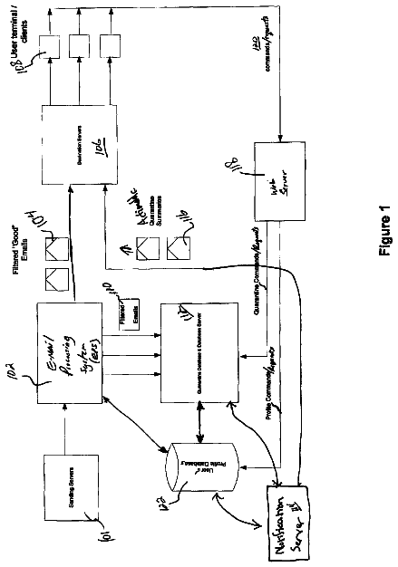
Actionable quarantine summary
Disclosed herein are systems, methods and the like for the management of filtered messages and filtering settings.
US 8,583,745 B2 · Assignee: OpenDesign, Inc. · Inventors: Bearman; Rob et al.
Sheet 1 of 34 from the published document. All sheets in the USPTO PDF
A method and system for mapping logical identifiers to physical identifiers is provided. In one embodiment, a logical routing system allows each application, or more generally entity (e.g., user of an application), to register its logical identifier to physical identifier mapping when the application starts executing on a computer. To send a message to an application identified by a logical identifier, a client program uses the registered mapping to identify the physical identifier of the computer. If an application later starts executing on a different computer, then the application can register a different mapping.
The described technology generally relates to mapping of logical identifiers to physical identifiers. Application programs such as a Web browser access resources using the HTTP protocol. The HTTP protocol uses a Uniform Resource Identifier ("URI") to identify a resource to be accessed. A URI is either a Uniform Resource Locator ("URL") or Uniform Resource Name ("URN"), or any other formatted string that identifies a network resource. URLs, as an example of URIs, are discussed in detail in T. Berners-Lee et al., Uniform Resource Locators (URL), RVC 1738, CERN, Xerox PARC, Univ. of Minn., December 1994. Each URL contains a domain name identifying where the resource is located. For example, the URL "http://www.odi.com/home.htm" indicates that the resource named "home.htm" is located at the domain of "odi.com." The HTTP protocol uses an underlying transport layer such as TCP/IP to route mess
1 of 34 drawing sheets so far from the published document, cropped to the drawing. Every sheet is in the USPTO PDF.
What the patent claimed, word for word. All of it is now free to use.
The described technology generally relates to mapping of logical identifiers to physical identifiers.
Application programs such as a Web browser access resources using the HTTP protocol. The HTTP protocol uses a Uniform Resource Identifier ("URI") to identify a resource to be accessed. A URI is either a Uniform Resource Locator ("URL") or Uniform Resource Name ("URN"), or any other formatted string that identifies a network resource. URLs, as an example of URIs, are discussed in detail in T. Berners-Lee et al., Uniform Resource Locators (URL), RVC 1738, CERN, Xerox PARC, Univ. of Minn., December 1994. Each URL contains a domain name identifying where the resource is located. For example, the URL "http://www.odi.com/home.htm" indicates that the resource named "home.htm" is located at the domain of "odi.com." The HTTP protocol uses an underlying transport layer such as TCP/IP to route messages to the computer associated with the domain name identified in the URL. The TCP/IP protocol, however, identifies computers using IP addresses (e.g., "128.32.0.6") rather than domain names. Various computer techniques have been developed to map logical identifiers, such as domain names, to physical identifiers, such as IP addresses.
One such technique is implemented by the domain name service ("DNS") that is provided as part of the TCP/IP protocol suite used by the Internet. DNS is a name service that maps domain names to IP addresses. When an application uses the HTTP protocol to send a message to a domain name, it at first requests a resolver program to resolve the domain name to its corresponding IP address. The resolver program accesses a hierarchy of domain name servers to resolve the domain name. The resolver program located at the computer where the application is executing requests a lowest-level domain name server to provide the IP address for the domain name. If that lowest-level domain name server does not have the IP address for that domain name, the domain name server forwards the request to the next higher-level domain name server. The request is propagated up the hierarchy of domain name servers until the IP address is found or until the authoritative domain name server for the first-level domain (e.g., ".com") is located. The authoritative domain name server maintains a mapping from the domain names to the IP addresses for all the domain names that have been registered for that first-level domain. The domain name servers that are lower in a hierarchy use a caching mechanism to maintain mappings from domain names to IP addresses that are provided by the authoritative domain name server. When a domain name is registered, it is assigned an IP address and a table of the authoritative domain name server is updated to reflect the mapping of that domain name to the IP address. The maintaining of mappings from domain names to IP addresses is provided by an administrative function of the authoritative domain name server. A user at the authoritative domain name server uses the administrative function to maintain the mappings.
A difficulty with the architecture of DNS is that the mapping of domain names to IP addresses is changed by an administrator at the authoritative domain name server. Another difficulty with the architecture is that a domain name maps to a single IP address. It would be desirable to have a technique for mapping logical identifiers to physical identifiers without the difficulties associated with DNS.
FIG. 1 is a block diagram for illustrating the logical routing system in one embodiment.
FIG. 2 is a flow diagram illustrating the processing when a client program sends a message to an application.
FIG. 3 is a block diagram for illustrating the logical routing system where instances of the application are executing at multiple nodes.
FIG. 4 is a block diagram illustrating use of the node identification function to effect load balancing for an application.
FIG. 5 is a block diagram illustrating the architecture of the application layer 510, the logical routing layer 520 and the physical routing layer 530 used by the logical routing system.
FIG. 6 is a block diagram illustrating connections at the physical routing layer between various nodes.
FIG. 7 illustrates a data structure used by the logical routing layer in one embodiment.
FIG. 8 illustrates data structures used by the physical routing layer in one embodiment.
FIG. 9 is a flow diagram illustrating the processing of the send message function of the physical routing layer in one embodiment.
FIG. 10 is a flow diagram illustrating the processing of the "search for route to node" function in one embodiment.
FIG. 11 is a flow diagram illustrating the processing of the lookup node function in one embodiment.
FIG. 12 is a flow diagram illustrating the processing of the establish peer connection function in one embodiment.
FIG. 13 is a flow diagram illustrating the processing of the receive message function of the physical routing layer in one embodiment.
FIG. 14 is a flow diagram illustrating the processing of the forward message function of the physical routing layer in one embodiment.
FIG. 15 is a flow diagram illustrating the processing of the process node search function in one embodiment.
FIG. 16 is a flow diagram illustrating the processing of the send logical message function of the logical routing layer in one embodiment.
FIG. 17 is a flow diagram illustrating the processing of the resolve logical destination function of the logical routing layer in one embodiment.
FIG. 18 is a flow diagram illustrating the processing of the search logical destination function of the logical routing layer in one embodiment.
FIG. 19 is a flow diagram illustrating the processing of the get response function of the logical routing layer in one embodiment.
FIG. 20 is a flow diagram illustrating the processing of the process logical destination update function of the logical routing layer in one embodiment.
FIG. 21 is a flow diagram illustrating the processing of the user information function of the logical routing layer in one embodiment.
FIG. 22 is a flow diagram illustrating the processing of the receive logical message function of the logical routing layer in one embodiment.
FIG. 23 is a flow diagram illustrating the processing of the register logical name function of the logical routing layer in one embodiment.
FIG. 24 is a flow diagram illustrating the processing of the generate logical destination update function of the logical routing layer in one embodiment.
FIG. 25 is a flow diagram illustrating the processing of the process logical name search function of the logical routing layer in one embodiment.
FIG. 26 is a flow diagram illustrating the processing of an application initialization function in one embodiment.
FIG. 27 is a flow diagram illustrating the processing of a function of an application that receives a message from the logical routing layer.
A method and system for mapping logical identifiers to physical identifiers is provided. In one embodiment, a logical routing system allows each application or entity (e.g., user of an application) to register its logical identifier to physical identifier mapping when the application starts executing on a computer. To send a message to an application identified by a logical identifier, a client program uses the registered mapping to identify the physical identifier of the computer. If an application later starts executing on a different computer, then the application can register a different mapping. In one embodiment, the logical routing system allows an application to register a function that is used to generate the physical identifier for the logical identifier associated with the application. The use of a function allows the mapping to physical identifier to vary based on various criteria, such as location of a client computer or workload balancing goals. The logical routing system also allows a logical identifier to map to multiple physical identifiers. With such a mapping, a client program would send a message to each of the computers identified by the multiple physical identifiers.
FIG. 1 is a block diagram for illustrating the logical routing system in one embodiment. The logical routing system is used to send messages between client computer systems 101 ("client nodes") and application computer systems 103 ("application nodes"). The computer systems are interconnected through a communications mechanism 104, such as the Internet. Applications executing at application nodes provide services to client programs executing at client nodes. The logical routing system provides a logical naming mechanism that allows client nodes to send messages to (e.g., requesting services of) applications by identifying the application by a logical identifier (also referred to as a "logical destination"), rather than a physical identifier (also referred to as a "node identifier"). For example, a logical identifier of an application may be "address book," whereas a physical identifier may be a globally unique identifier that uniquely identifies the node where the application is executing. (This description uses an "address book" as an example application. An address book application maintains a mapping of names (e.g., John Smith) of people to electronic mail addresses (e.g., JohnSmith@company.com). The address book application receives messages from client programs requesting an electronic mail address for a person and sends a response message to the client program that includes the electronic mail address.) When a client node (or more precisely, a computer program executing at the client node) wants to send a message to an application, it provides the message to a logical routing system along with the logical identifier of the application. The logical routing system identifies the appropriate physical identifier of the node where the application is executing and sends the message to that node. When an application starts its execution at an application node, it registers with the logical routing system. The logical routing system may maintain a mapping from logical identifiers of applications to physical identifiers of the application nodes where the applications are executing. A client node may identify the physical identifiers of an application from the logical identifier using this mapping. A logical identifier may map to multiple physical identifiers of different application nodes. For example, multiple copies of the address book application may be executing at different application nodes to accommodate the demands of the client program. When a client program wants to retrieve an address, then the logical identifier of the retrieve address function might map to only one physical identifier. In contrast, when a client program wants to insert an address, then the logical identifier of the insert address function might map to all the physical identifiers of nodes where the application is executing. The logical routing system thus provides a mechanism that allows client programs to be developed using logical identifiers of applications and allows the logical identifiers to be resolved to physical identifiers during execution of the client programs. One skilled in the art would appreciate that a program executing at a node can be both an application and a client program in that it may respond to requests for services from client programs and request services from other applications.
Applications register themselves with the logical routing system to map their logical identifiers to physical node identifiers. The logical routing system may maintain a logical routing map of these registrations. The logical routing system can implement the logical routing map across the application nodes and client nodes in a distributed manner, can implement the logical routing map as a central system, or can implement the logical routing map by a combination of distributed and centralized systems. When an application registers with the logical routing system, a register message may be sent to a logical destination that identifies the logical routing map (e.g., "logical routing map"). Similarly, when a client program sends a message to an application, the logical routing system may send a message to the same logical destination to retrieve the physical identifiers of the application. More generally, the logical routing map may be considered to be an "application" that is not only used by the logical routing system, but is also accessible through the logical routing system itself.
In one embodiment, the logical routing map has a node identification function for each logical name that returns the node identifier of the node associated with that logical name. When the application associated with a logical name registers with the logical routing system, the application provides its node identification function to the logical routing system. The node identification function may input parameters or criteria (e.g., the message to be sent) and returns the appropriate node identifier for those parameters or criteria. For example, applications associated with a logical name may be executing at nodes physically located on each continent. The node identification function may input the country where the sending node is located and return the node identifier for the node located on the continent in which the country is located.
FIG. 2 is a flow diagram illustrating the processing when a client program sends a message to an application. In block 201, an application when it starts execution registers its logical identifier and the physical identifier of the node at which it is currently executing with the logical routing system. (Client programs register in a similar way.) In one embodiment, rather than registering the actual physical identifier, a node identification function is registered. Whenever the physical identifier is needed, the node identification function is invoked, passing the message to be sent, and returns one or more physical identifiers. For example, the address book application may register a node identification function that maps the last name of a person to the physical identifier of the node that is executing the instance of the application that is responsible for servicing requests with that last name. In block 202, the logical routing system stores the mapping of logical identifier to physical identifier for the application. In block 203, the client program invokes the logical routing system to send a message to an application identified by a logical identifier. In block 204, the logical routing system identifies the physical identifier using the logical routing mapping. The logical routing system at the client node invokes the node identification function passing the message. The node identification function returns the physical identifier associated with an instance of application. The logical routing system sends the message to the node addressed by that physical identifier. The logical routing system at the application node, upon receiving the message, may determine whether the message should be forwarded to another node or processed by this node. The logical routing system may use a node identification function to identify the node that is to process the message. In block 206, assuming that the message is to be processed at this node, the application processes the message. In block 207, the application sends a response to the client node using the logical routing system. The logical routing system may also send an updated node identification function to the client node. The client node receives the response and the updated notification of function. The logical routing system at the client node passes the response to the client program and uses the updated node identification function when sending subsequent messages to the logical identifier. The updated node identification function may reflect the changing architecture of how the application is distributed across multiple application nodes.
FIG. 3 is a block diagram for illustrating the logical routing system where instances of the application are executing at multiple nodes. The application is executing at application nodes 303, 305 and 306. The application was initially executing only one instance at application node 303. As the demand for the address book services increased, application nodes 305 and 306 were brought online and started executing instances of the application. The application node 303 services requests for names beginning with the letters A-J, application node 305 services requests for names beginning with the letters K-S, and application node 306 services requests for names beginning with the letters T-Z. Continuing with the example of FIG. 2, when the client program wants to request an address for "John Smith," the logical routing system uses the node identification function for the logical identifier of "address book," which identifies application node 303. The logical routing system sends the request to application node 303. When the logical routing system at application node 303 receives the request, it uses its node identification function to identify application node 305. The logical routing system of application node 303 forwards the request to application node 305, where the logical routing system provides the message to the application. The instance of the application executing at application node 305 retrieves the electronic mail address and sends the address to the client node. The logical routing system of application node 305 may also send to the client node an updated node identification function that maps names beginning with the letters A-J to application node 303, names beginning with the letters K-S to application node 305 and names beginning with the letters T-Z to application node 306. In this way, when the logical routing system of the client node next uses the updated node identification function, it will identify the appropriate application node that is responsible for servicing the request and send the request directly to the identified application node. Alternatively, if application node 305 does not send an updated node identification function, then subsequent requests will be routed through application node 303. If multiple instances of an application provide the same capabilities, then the node identification function may select the physical identifier of an instance randomly, may select the physical identifier based on geographic proximity to the client node, and so on.
FIG. 4 is a block diagram illustrating use of the node identification function to effect load balancing for an application. The client nodes 401 use a node identification function that maps to one of the load balancing nodes 402. For example, the node identification function may randomly select one of the load balancing nodes. The node identification function used by the client nodes may be provided by the load balancing nodes. When a load balancing node receives a request from a client node, it uses a different node identification function provided by the application to identify the application node 403 that is to service the request. For example, there may be multiple instances of the address book application that services requests for names beginning with the letters A-J. Each load balancing node can decide in which of those instances to send a request.
FIG. 5 is a block diagram illustrating the architecture of the application layer 510, the logical routing layer 520 and the physical routing layer 530 used by the logical routing system. The logical routing system corresponds to the functionality provided by the logical routing layer in one embodiment. The physical routing layer is responsible for sending a message to a node identified by a node identifier. Each node in the network is assigned a unique node identifier. The physical routing layer provides a send message component 531 and a receive message component 532. The logical routing layer sends messages using the send message component and receives messages via the receive message component. The send message component is passed a message and a destination node identifier and locates the network address (e.g., IP address and port) for that destination node identifier. The send message component then invokes the underlying transport layer, such as TCP/IP, to deliver the message to the network address. The send message component may request a physical routing map to provide the network address for the destination node identifier or may request other nodes to which it is connected (i.e., peer nodes) if they know of the network address for the destination node. The send message component may cache the network address in a physical routing table for use when sending subsequent messages to that destination node. The send message component then sends the message to that network address. The message may be sent by establishing a direct connection between the originating node and the destination node, by forwarding the message to the destination node via a peer node of the originating node, or by sending a message to a physical routing server for forwarding to the destination node. The send message component uses a "search for route to node" component 533, a lookup node component 534 and establish peer connection component 535, as described below in more detail. The receive message component processes messages that are received for a destination node. If this node (i.e., the node where a component is executing) is not the destination node, then the receive message component attempts to forward the message to the destination node. If the message indicates that an originating node is searching for a path to a destination node, then this node either responds to the search request, if it knows a path to the destination node, or forwards the search request to its peer nodes. If the message is intended for processing at this node, then the receive message component passes the message to the logical routing layer by invoking the receive logical message component 522 or the process logical name search component 529A.
The logical routing layer provides a send logical message component 521, a receive logical message component 522, a register logical name component 523 and a process logical name search component 529A. The application layer sends messages to a logical destination, which may be an application or a user, using the send logical message component and receives response messages from the logical destination via the receive logical message component. The send logical message component is passed a logical identifier and a message, identifies the destination node identifier for the logical identifier, and uses the send message component of the physical routing layer to send the message to the destination node. The send logical message component may identify the destination node identifier using a node identification function provided by a central server, by a search of peer nodes, or by the logical destination itself. The send logical message component may cache the mapping of the logical identifier to the node identification function. The send logical message component uses a resolve logical destination component 524, a user information component 525, a logical destination search component 526, a get response component 527, and a process logical destination update component 528 that are described below in detail. The receive logical message component is invoked by the receive message component of the physical routing layer to pass the message to the logical routing layer. The receive logical message component processes the message and provides the message to the application layer. The register logical name component is used by the application layer to register a logical identifier with the logical routing layer. The generate logical destination update component is invoked by the process logical name search component. The application layer may provide an application initialization component 511 and an application receive component 512. The application initialization component may register the application's logical identifier with the logical routing layer. The application receive component is invoked by the receive logical message component to effect the passing of the message from the logical routing layer to the application layer. The application layer also invokes the send logical message to send messages to a logical destination.
The logical routing system may execute on computer systems that include main memory, a central processing unit, input devices (e.g., keyboard and pointing devices), output devices (e.g., display devices) and a hard drive. The main memory and hard drive are computer-readable media that may contain instructions that implement the logical routing system. The computer systems may be interconnected via various communication channels that include the Internet, a wide area network, a point-to-point dial-up connection, or a local area network.
FIG. 6 is a block diagram illustrating connections at the physical routing layer between various nodes. In this example, client node 602 is connected to client node 603, and client node 603 is connected to application node 604. When the physical routing layer of client node 602 is to send a message to application node 604, which is identified by a destination node identifier, the send message component may attempt to establish a direct connection with the application node. However, if a connection cannot be established, then the send message component of client node 602 determines whether the application node is accessible through any of its peer nodes. In this case, application node 604 is accessible to client node 602 via client node 603. Thus, the client node 602 forwards the message to client node 603, which in turn forwards the message to application node 604.
FIG. 7 illustrates a data structure used by the logical routing layer in one embodiment. The logical name table 701 (also referred to as a logical routing table) contains an entry for each logical name associated with an application executing at the node. A logical name is a logical identifier that identifies an application. A logical identifier may also identify a user or some other logical destination. Each entry includes a logical identifier, a fully qualified logical identifier, a class and a node identification function. The fully qualified logical identifier uniquely identifies the logical name associated with the application. The class identifies a message class of the logical destination. For example, the class may be database, application or user. A logical identifier is unique within a class. The node identification function is used by client nodes to identify the node identifier to which a message for the logical name should be sent. Each entry may also include a function name which identifies a function supported by the application. For example, a function name of an address book application for inserting a new entity may be "insert address." The logical name table contains an entry for each logical destination known to this node. The logical name table may also contain mapping of user names to user identifiers. The user name is the logical name. The fully qualified logical name is the user identifier that uniquely identifies the user. There may be more than one user name associated with a user identifier. In an alternate embodiment (described below), the logical routing table includes a key function, criteria declaration, and route table. The criteria defines the data to be passed to the key function to generate a key. The key is then used to locate the node identifier from the route table.
FIG. 8 illustrates data structures used by the physical routing layer in one embodiment. The data structures of the physical routing layer include a physical routing table 801 and a peer table 802. The physical routing table contains an entry for each node identifier known to this node. Each entry maps the node identifier to the peer node identifier through which the node identifier is accessible. The peer table contains an entry for each peer node of this node. Each entry maps the node identifier to the network address of the peer node.
FIGS. 9-15 are flow diagrams illustrating the processing of the physical routing layer in one embodiment. FIGS. 9-12 illustrate the send processing of the physical routing layer. FIG. 9 is a flow diagram illustrating the processing of the send message function of the physical routing layer in one embodiment. The function is passed a destination node (i.e., component) identifier and a message and sends the message to the identified destination node. This function is invoked by the logical routing layer. In decision block 901, if an entry for the destination node identifier is in the physical routing table, then a route to the destination node has previously been identified and the function retrieves that entry and continues at block 902, else the function continues at block 905. In block 902, the function adds to the header of the message route information that includes the node identifier of this node. When a message is received by a node, it will have a history of the nodes on the path traveled so far. The receiving node can update its physical routing table to indicate that the nodes on that path are accessible. In block 903, the function retrieves the node identifier of the peer node from the entry and then retrieves the network address (e.g., the IP address and port number) for that peer node from the peer table. The function then sends the message to the retrieved network address. In decision block 904, if sending the message was successful, then the function returns an indication of success, else the function returns an indication of error. Blocks 905-914 are performed when an entry for the passed node identifier is not in the physical routing table. These blocks attempt to find a route through which the message can be sent to the destination node. In block 905, the function invokes the "search for route to node" function, which searches for a peer node through which the destination node is accessible. If the invoked function finds such a peer node, then it adds an entry to the physical routing table and returns an indication of success. In decision block 906, if a route was found, then the function continues at block 907, else the function continues at block 908. In block 907, the function retrieves the entry for the destination node from the physical routing table and continues at block 902 to send the message to the destination node. In decision block 908, if the policy for this node allows for a new peer connection to be created, then the function continues at block 909, else the function continues at block 912. An example policy may limit the number of connections to peer nodes to four. If this node already has four peer nodes, then the policy prevents connection to a fifth peer node. In block 909, the function invokes the lookup node function, which identifies the network address for the destination node and adds it to the peer table. The invoked function may send a message to a server node to see if the destination node has registered with the server node. The invoked function also adds an entry to the peer table to store the node identifier and network address for the destination node. In decision block 910, if the destination node was found, then the function continues at block 911, else the function continues at block 914. In block 911, the function invokes the establish peer connection function to establish a peer connection with the destination node and to update the physical routing table. In decision block 912, if a connection is established to the destination node, then the function continues at block 907 to send the message directly to the destination node, else the function continues at block 913. In decision block 913, if the policy of this node allows for server node forwarding, then the function continues at block 903 to forward the message to the server node, else the function returns an indication of error. When server node forwarding is allowed, this node sends the message to the server node so that the server node can forward the message to the destination node either now if the destination node is online or later when the destination node comes online. In decision block 914, if the message should be dropped, then the function returns an indication of error, else the function continues in block 913.
FIG. 10 is a flow diagram illustrating the processing of the "search for route to node" function in one embodiment. The function is passed the node identifier of the destination node. The function is invoked to identify a path from a peer node of this node to the destination node. The function sends a message to each peer node of this node indicating that this node is searching for a path to the destination node. A peer node responds to the message when it has identified a path through the peer node to the destination node. One skilled in the art will appreciate that different searching techniques may be used. For example, the messages may be sent to the peer nodes so that each peer node can attempt to identify a path before a message is sent to the next peer node, rather than initially sending a message to each peer node. In decision block 1001, if this node has any peer nodes, then the function continues at block 1002, else the function returns an indication of error. In block 1002, the function creates a node search message that includes the identifier of this node and the destination node. In block 1003, the function sends a copy of the node search message to each peer node of this node. In block 1004, the function sets a timer to limit the time that this node waits for a response from a peer node. In block 1005, the function waits for a response from a peer node or for a timeout. In decision block 1006, if a response was received, then the function continues at block 1007, else the timeout occurred and the function returns an indication of error. In block 1007, the function updates the physical routing table by adding an entry to indicate that the destination node is accessible through the peer node that sent the response. The function cancels the timer and then returns an indication of success.
FIG. 11 is a flow diagram illustrating the processing of the lookup node function in one embodiment. This function is passed the node identifier of the destination node. The function contacts the server node to retrieve the network address for the destination node and adds an entry to the peer table if the server node responds with the network address of the destination node. In decision block 1101, if the appropriate connection to the server node is available, then the function continues at block 1101, else the function returns an indication of error. In block 1102, the function creates a lookup node message that includes the destination node identifier. In block 1103, the function sends the lookup node message to the server node. In block 1104, the function sets a timer. In block 1105, the function waits for a response from the server node or a timeout. In decision block 1106, if a response is received from the server node, then the function continues at block 1107, else a timeout has occurred and the function returns an indication of error. In block 1107, the function adds an entry to the peer table that indicates the network address of the destination node, which was returned in the message. The function cancels the timer and then returns an indication of success. In an alternate embodiment, if the server node is not available through this node, then this node may request its peer nodes to contact the server node on its behalf or may check locally cached information relating to the network address of various nodes.
FIG. 12 is a flow diagram illustrating the processing of the establish peer connection function in one embodiment. This function is passed the identifier of the destination node. The function establishes a connection with the destination node and updates the physical routing table. In block 1201, the function looks up the destination node identifier in the peer table. In decision block 1202, if the network address of the destination node is in the peer table, then the function continues at block 1203, else a connection cannot be established and the function returns an indication of error. In block 1203, the function creates a peer connect request message that identifies this node. In block 1204, the function sends the peer connect request message to the network address for the destination node. To send the message, the function establishes a transport level connection to the network address and then sends the message. If a connection cannot be established, then the function returns an indication of error. In block 1205, the function sets a timer. In block 1206, the function waits for a response from the destination node or a timeout. In decision block 1207, if a response is received from the destination node, then the function continues at block 1208, else a timeout occurred and the function returns an indication of error. In block 1208, the function cancels the timer. In decision block 1209, if the response indicates that a connection can be established, then the function continues at block 1210, else the destination node is not willing to connect to this node and the function returns an indication of error. In block 1210, the function authenticates the destination node. Various well-known authentication techniques can be used, such as use of public/private key pairs in which the destination node sends a message encrypted with its private key and this node decrypts the message using the public key. If the destination node cannot be authenticated, then the function returns an indication of error. In block 1211, the function updates the physical routing table to indicate that the destination node is accessible as a peer node (i.e., connected at the physical routing layer) and then returns an indication of success.
The description continues in the full USPTO document.
About 6,178 words. The USPTO PDF has it with every drawing.
Fees are due 3.5, 7.5 and 11.5 years after grant. This patent expired on November 12, 2025, so the fee marked "not paid" was the one that went unpaid.
APPLICATION PLATFORM
Filed May 2008 · published Mar 2009Application platform
Filed May 2008 · granted Nov 2013Earlier publications, parents and continuations. None of them can still be enforced, or this patent would not be listed.
Prior art cited by the examiner or applicant. Useful when you check your own idea for novelty.
Everything on this page comes from the documents linked above.