Background of the invention
1. Field of the invention
The present invention relates to a solid-state image sensing device and a camera system using the same.
2. Description of the related art
In recent years, the demand for solid-state image sensing devices has been rapidly increasing for use in image capturing apparatuses, such as, mainly, digital still cameras and video camcorders. As such solid-state image sensing devices, CCDs (Charge Coupled Devices) or MOS solid-state image sensing devices have been used. The former, as compared to the latter, are widely used as high-definition image sensing devices, due to their high sensitivity and low noise, but, on the other hand, have some disadvantages. Specifically, the power consumption and the drive voltage are high and the cost is high since a general semiconductor manufacturing process cannot be used. Additionally, it is difficult to integrate peripheral circuits, such as a drive circuit.
For these reasons, much effort has been devoted to the development of an amplifying-type MOS solid-state image sensing devices. In an amplifying-type solid-state image sensing devices, signal charge that is stored in a photodiode is introduced into the control electrode of an amplifying transistor, provided in each pixel, is amplified by the amplifying transistor, and the resulting output is output from the main electrode thereof in accordance with the amount of signal charge. In particular, for amplifying-type solid-state image sensing devices, efforts have been directed to the development of CMOS sensors using MOS transistors as amplifying transistors. The demand for portable telephones is projected to increase, and it is expected that MOS solid-state image sensing devices, which can overcome the above-described disadvantages of CCDs, will be applied to portable apparatuses.
FIG. 13 is a circuit diagram of a typical example of a CMOS sensor pixel for use in a solid-state image sensing device.
In FIG. 13, reference numeral 30 represents a unit pixel, 1 is a photodiode for storing signal charge generated from incident light, 6 is a amplifying MOS transistor for outputting an amplified signal in accordance with the amount of signal charge, and 3 is a floating diffusion (hereinafter may be referred to as "FD") region which receives a signal charge and connects the signal charge to the gate electrode of the amplifying MOS transistor 6. Reference numeral 2 represents a transfer MOS transistor for transferring signal charge stored in the photodiode 1 to the FD region 3, 4 is a reset MOS transistor for resetting the FD region 3, and 5 is a selection MOS transistor for selecting an output pixel. Reference numeral 9a is a control line for applying a pulse to the gate of the transfer MOS transistor 2 to control the charge-transfer operation, 9b is a control line for applying a pulse to the gate of the reset MOS transistor 4 to control the reset operation, and 9c is a control line for applying a pulse to the gate of the selection MOS transistor 5 to control the selection operation. Reference numeral 10a is a power-supply wire which is connected to the drain of the amplifying MOS transistor 6 and the drain of the reset MOS transistor 4 to provide a power-supply potential thereto. Reference numeral 10b is an output line for outputting an amplified signal of a selected pixel, 8 is a constant-current MOS transistor that operates as a constant current source and that forms a source follower in conduction with the amplifying MOS transistor 6, and 10c is a wire for supplying a potential to the gate electrode of the MOS transistor 8 so as to operate thereof at constant current.
An arrangement of a plurality of the above-described pixels 30 in a two-dimensional matrix provides a pixel area for a two-dimensional solid-state image sensing device. In the matrix configuration, the output line 10b is used as a common line for pixels in the same column and the control lines 9a, 9b, and 9c are each used as a common line for pixels in the corresponding row. Only pixels in a row that is selected by the control line 9c output signals to the corresponding output line 10b.
FIG. 14 is a circuit diagram of another pixel for a conventional solid-state image sensing device. In FIG. 14, reference numeral 1 represents a photodiode, 2 is a transfer MOS transistor for transferring charge of the photodiode 1, and 3 is a floating diffusion region for temporarily storing the transferred charge. Reference numeral 4 is a reset MOS transistor for resetting the floating diffusion region 3 and the photodiode 1, 5 is a selection MOS transistor for selecting one row in the array, and 6 is a source-follower MOS transistor. This source-follower MOS transistor 6 converts charge in the floating diffusion region 3 into a voltage and amplifies the voltage using a source-follower amplifier. Reference numeral 7 represents a read line, which is used as a common line in the same column, for reading a pixel voltage signal, and reference numeral 8 represents a constant current source for providing constant current to the read line 7.
The operation of this conventional solid-state image sensing device will be briefly described below. The photodiode 1 converts incident light into charge, and the transfer MOS transistor 2 causes the charge to be stored in the floating diffusion region 3. The potential of the floating diffusion region 3 and the photodiode 1 is reset to a constant potential in advance by opening the reset MOS transistor 4 and the transfer MOS transistor 2. Thus, the potential of the floating diffusion region 3 varies in accordance with charge generated from incident light.
The potential of the floating diffusion region 3 is amplified by the source-follower MOS transistor 6 and is output to the read line 7. When the selection MOS transistor 5 is open, that pixel is selected. An output circuit (not shown) detects optical signal components by determining the difference between the potential of the floating diffusion region 3 after optical signals are stored and the reset potential of the floating diffusion region 3.
FIG. 15 is a schematic sectional view of the solid-state image sensing device shown in FIG. 13. This schematic sectional view includes portions corresponding to the photodiode, the transfer MOS transistor, and the FD region. In this figure, reference numeral 11 represents an n-type semiconductor substrate, 12 is a p well, and 15 is an n-type semiconductor region formed in the p well 12. The p well 12 and the n-type semiconductor region 15 constitute a photodiode. Signal charge generated from incident light is stored in the n-type semiconductor region 15. Reference numeral 14 is a gate electrode of the transfer MOS transistor 2 shown in FIG. 13. Reference numeral 18 represents an FD region, which is an n-type semiconductor region formed in the p well 12 and also serves as the drain region of the transfer MOS transistor 2. The source region of the transfer MOS transistor corresponds to the n-type semiconductor region 15. Reference numeral 20 represents a wire that is connected to the FD region 18 and also to the gate electrode of an amplifying MOS transistor (not shown). Reference numeral 17 is an element-isolating insulating film, which is called a "LOCOS" oxide film. Reference numeral 29 is a p+ channel stopper, which is formed under the element-isolating insulating film 17 and has a doping concentration higher than the p well 12.
FIG. 16 is a schematic sectional view of the solid-state image sensing device shown in FIG. 14. This sectional view shows a combination of portions corresponding to the photodiode 1 and the transfer MOS transfer 2 shown in FIG. 14. Reference numeral 11 represents an n-type silicon substrate, 12 is a p well, 13a is a gate oxide film of the transfer MOS transistor 2, 13b is a thin oxide film provided on a light-receiving portion, 14 is the gate electrode of the transfer MOS transistor 2, and 15 is an n-type cathode of the photodiode 1. Reference numeral 16 represents a p-type surface region for providing a photodiode-buried structure, and 17 is a LOCOS oxide film for element isolation. Reference numeral 18 is a heavily-doped n-type region that forms a floating diffusion region and also acts as the drain region of the transfer MOS transistor 2. Reference numeral 19 is a silicon oxide film for providing insulation between the gate electrode and a first metal layer 21. Reference numeral 20 is a contact plug, 22 is an interlayer insulting film for providing insulation between the first metal layer 21 and a second metal layer 23, 24 is an interlayer insulating film for providing insulation between the second metal layer 23 and a third metal layer 25, and 26 is a passivation film. For a color photoelectrical conversion device, a color filter layer (not shown) is formed at the upper layer of the passivation film 26 and a micro-lens (not shown) is further formed thereon to improve the sensitivity. Incident light through the surface enters the photodiode through an aperture where the third metal layer 25 is not provided. The light is absorbed by the n-type cathode 15 of the photodiode or the p well layer 12, so that electron-hole pairs are produced. Of these pairs, electrons are stored in an n-type cathode region.
U.S. Pat. No. 6,403,998 discloses a solid-state image sensor in which a p-type buried layer is formed at a predetermined distance from an n-type substrate and a photoelectric conversion section is formed thereabove. In addition, U.S. Pat. No. 6,504,193 discloses a solid-state image device in which one end of a photodiode is formed to extend to a position under a readout gate and a punch-through stopper region is formed under a signal detection portion, which corresponds to the drain region, to be in self-alignment with the gate electrode.
With the conventional structures shown in FIGS. 15 and 16, however, part of signal charge generated below the photodiode is not absorbed by the photodiode, and is, in turn, absorbed by the FD region 18 and the source and drain regions of the transistor within the pixel. As a result, the sensitivity decreases.
Additionally, although various improvements have been made to CMOS solid-state image sensing devices, there is still a problem in that the sensitivity is low, particularly, in a device having a small pixel size. The present invention provides a CMOS solid-state image sensing device that has a novel structure and that can provide high sensitivity even for micro pixels.
A description is now given to a reason why the sensitivity in the conventional structure shown in FIG. 16 is low. Referring to FIG. 16, electrons that are generated from a light ray 27 entering the aperture are successfully stored in the n-type cathode region and serve as an effective signal charge. However, for example, as in the case of a light ray 28, electrons that are generated at a position somewhat away from the photodiode may be captured, not by the n-type cathode region, but by the n+ type floating diffusion region 18 where the potential is lower. In addition, even immediately under the photodiode, as a result of repeated diffusion and drift of electrons, the electrons are absorbed by a low potential region other than the photodiode with a certain probability and thus do not contribute as photoelectric conversion signals. When the n-type cathode 15 is formed at a position deeper relative to the silicon surface, such an arrangement facilitates the photodiode to collect the electrons. However, since the n-type cathode region is formed in the p well region 12 by ion implantation, the doping concentration cannot be reduced so significantly. This conventional structure also has a problem in that the n-type cathode 15 cannot be formed with a high doping concentration at a considerably deep position, due to the limitation of depletion behavior of the n-type cathode 15.
Thus, the volume of the n-type cathode, which provides the photodiode, is limited. Consequently, a sufficient ability of collecting electrons generated from incident light cannot be achieved, resulting in low sensitivity.
Meanwhile, the conventional structure disclosed in U.S. Pat. No. 6,403,998 also cannot prevent electrons that are generated at a deep position in response to incident light from being absorbed by the floating diffusion region 18 or the like, since no potential barrier is provided under the signal readout gate. Thus, this structure also has a problem in that the sensitivity decreases. Also, the conventional structure disclosed in U.S. Pat. No. 6,504,193 cannot prevent some of electrons that are generated from incident light from being absorbed by the source and drain of another transistor in the pixel or from being absorbed by adjacent pixels, since the punch-through stopper region is formed only under a signal detection portion. Thus, this structure also has a problem in that the sensitivity decreases as well.
Summary of the invention
It is an object of the present invention to provide a solid-state image sensing device that has high sensitivity, particularly, for micro pixels, and another object of the present invention is to provide a camera system that are low in power consumption and in drive voltage and low in cost.
To achieve the foregoing objects, according to a first aspect of the present invention, there is provided a solid-state image sensing device. The solid-state image sensing device has a plurality of pixels. Each pixel includes a photodiode that is constituted by a semiconductor region having a first conductivity type and a semiconductor region having a second conductivity type to generate signal charge. The first conductivity type and the second conductivity type are opposite to each other. Each pixel further includes a first transistor that has a drain region, which has the first conductivity type formed in the second-conductivity-type semiconductor region to transfer the signal charge to the drain region, and a second transistor that has a source region and a drain region, which are formed in the second-conductivity-type semiconductor region and which have the first conductivity type. At least one potential barrier having the second conductivity type is provided under the drain region of the first transistor and the source region and/or the drain region of the second transistor. With arrangement, since the at least one potential barrier is provided under an FD region and the source electrode and/or the drain electrode of each transistor, thereby increasing the sensitivity. This is because signal charge that is generated below the potential barrier is not absorbed by the FD region and the source region and/or the drain region, under which the potential barriers are provided, of each transistor.
According to a second aspect of the present invention, there is provided a solid-state image sensing device. The solid-state image sensing has at least one pixel. Each pixel includes a photodiode that is constituted by a semiconductor region having a first conductivity type and a semiconductor region having a second conductivity type. The first conductivity type and the second conductivity type are opposite to each other. Each pixel further includes a transistor that has a source region and a drain region which are provided in the first-conductivity-type semiconductor region and which have the first conductivity type. A potential barrier having the second conductivity type is provided under the gate electrode of the transistor. With this arrangement, the potential barrier that is provided under the gate electrode of an n-type transistor, which constitutes the pixel, prevents short-circuiting between the source and drain. The potential barrier also serves to allow the n-type transistor, provided even in an n-type semiconductor region, to operate.
According to a third aspect of the present invention, there is provided a solid-state image sensing device. The solid-state image sensing device includes a substrate having a first conductivity type, a layer having a second conductivity type, and a layer having the first conductivity type. The second-conductivity-type layer and the first-conductivity-type layer form a photodiode. At least one potential barrier, which is formed by a region having the second conductivity type, is provided around a region where the photodiode is formed.
The second-conductivity-type region may be provided in the first-conductivity-type layer and the second-conductivity-layer may be a buried layer. The second-conductivity-type region may extend to the second-conductivity-type buried layer in the depth direction. With this arrangement, when an n-type layer for the photodiode is surrounded by the buried layer having the opposite conductivity type and the layer having the same conductivity type as that of the buried layer, potential barriers are provided against electrons. In addition, this arrangement allows the photodiode to have a low doping concentration and to have a large volume, thereby increasing a collecting ability of optical signals.
The potential barrier may be constituted by a plurality of potential barriers that is arranged at a plurality of layers in the depth direction of the first-conductivity-type layer. With this arrangement, in a structure having a deep n-type layer for the photodiode, that is, in a structure having sensitivity even at a longer wavelength, providing a plurality of p-type layers allows for formation of effective potential barriers.
The uppermost layer of the plurality of layers may control a charge transfer path from the photodiode to a transfer transistor. This arrangement can achieve a structure in which the transfer transistor can secure transfer of signals from the photodiode.
A portion in at least the vicinity of the opposite-conductivity-type buried layer in the first-conductivity-type layer may have a lower doping concentration than the surrounding opposite-conductivity-type layer. With this arrangement, when the photodiode is reverse biased at the time of storing charge, a depletion layer effectively extends toward the n-type layer to facilitate complete depletion. Since the well layer and the buried layer are placed at substantially the same position in the horizontal plane direction, less photomask processing is required. Thus, this arrangement can provide a higher isolation effect.
The first-conductivity-type layer may have a region having a doping concentration higher than the other regions, in a portion adjacent to the semiconductor surface. With this arrangement, electron potentials at the semiconductor surface become lower than in the other portions, and thus electrons gather in the vicinity of the surface at the time of storing charge. Consequently, electrons are less likely to remain at the time of transferring charge.
The first-conductivity-type layer may be completely depleted during charge transfer. This arrangement can provide a "complete-transfer" photodiode, which allows for the determination of the concentration in the depth direction so that the photodiode that is surrounded by the opposite-type-conductivity layer is depleted due to reverse biasing and which has no reset noise.
According to a fourth aspect of the present invention, there is provided a method for manufacturing the solid-state image sensing device of the third aspect of the present invention. In this manufacturing method, after the first-conductivity-type layer is formed on the opposite-conductivity-type buried layer, the opposite-conductivity-type layer is formed by ion implantation. This manufacturing method allows for the manufacture of a solid-state image sensing device that can deal with various spectral characteristics, by changing the thickness of the epitaxial layer.
According to a fifth aspect of the present invention, there is provided a method for manufacturing the solid-state image sensing device of the third aspect of the present invention. In this manufacturing method, the opposite-conductivity-type buried layer is formed in such a manner that, after ions are implanted into the first-conductivity-type semiconductor substrate, ions are implanted into the opposite-conductive-type buried layer. This manufacturing method allows for formation of a uniform buried layer within a surface in the depth direction with high reproducibility by ion implantation, when there is no need to have a significantly high spectral sensitivity at a longer wavelength.
In addition, an isolation region may be provided between adjacent pixels by STI (Shallow Trench Isolation). Since STI is used, even for minute pixels, it is possible to provide an image sensing device which has less charge leakage between adjacent pixels, which has low crosstalk, and which has high sensitivity.
The entire contact surface between an oxide film, which is formed by the STI and which isolates pixels, and silicon may be covered by the first-conductivity-type semiconductor layer. With this arrangement, a depletion layer is not formed at the interface between the oxide film and the silicon during STI, which can provide an image sensing device having less noise when it is dark.
An isolation region may be provided between adjacent pixels by deep trench isolation. With this arrangement, for minute pixels, isolations between the pixels can further be enhanced, which can provide an image sensing device having low cross talk and having high sensitivity.
The entire contact surface between an oxide film, which is formed by the deep trench isolation and which isolates pixels, and silicon may be covered by the first-conductivity-type semiconductor layer. With this arrangement, a depletion layer is not formed at the interface between the oxide film and the silicon during deep trench isolation, which can provide an image sensing device having less noise when it is dark.
Further objects, features and advantages of the present invention will become apparent from the following description of the preferred embodiments with reference to the attached drawings.
Brief description of the drawings
FIG. 1 is a schematic sectional view of a solid-state image sensing device according to a first embodiment of the present invention.
FIG. 2 is a schematic sectional view of a solid-state image sensing device according to a second embodiment of the present invention.
FIG. 3 is a schematic sectional view of a solid-state image sensing device according to a third embodiment of the present invention.
FIG. 4 is a schematic sectional view of a solid-state image sensing device according to a fourth embodiment of the present invention.
FIG. 5 is a schematic sectional view of a solid-state image sensing device according to a fifth embodiment of the present invention.
FIG. 6 is a schematic sectional view of a solid-state image sensing device according to a sixth embodiment of the present invention.
FIG. 7 is a schematic sectional view of a solid-state image sensing device according to a seventh embodiment of the present invention.
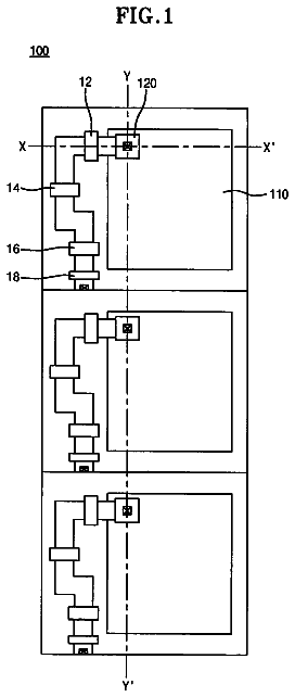
FIG. 8 is a plan view showing one example of a pixel of a solid-state image sensing device according to the present invention.
FIG. 9 is a schematic sectional view of a solid-state image sensing device according to an eighth embodiment of the present invention.
FIG. 10 is a schematic sectional view of a solid-state image sensing device according to a ninth embodiment of the present invention.
FIG. 11 is a circuit diagram of part of the solid-state image sensing device according to the present invention.
FIG. 12 is a block diagram of a camera system using the solid-state sensing device according to the present invention.
FIG. 13 is a circuit diagram of a typical example of a CMOS sensor pixel for use in a solid-state image sensing device.
FIG. 14 is a circuit diagram of a pixel of a conventional solid-state image sensing device.
FIG. 15 is a schematic sectional view of the solid-state image sensing device shown in FIG. 13.
FIG. 16 is a schematic sectional view of the solid-state image sensing device shown in FIG. 14.
Description of the preferred embodiments
First Embodiment
FIG. 1 is a schematic sectional view of a solid-state image sensing device according to a first embodiment of the present invention.
In FIG. 1, reference numeral 101 represents a semiconductor substrate having a first-conductivity-type (n-type in this case by way of example), 102 is a p well which is a second-conductivity-type semiconductor region, and 103 is an n-type semiconductor region which is formed in the p well 102 and which is a first-conductivity-type semiconductor region. The p well 102 and the n-type semiconductor region 103 constitute a photodiode. Signal charge that is generated from incident light is stored in the n-type semiconductor region 103. Reference numeral 111 represents a drain region of a transfer transistor, which is a first transistor, for transferring signal charge generated by the photodiode. The drain region has the first conductivity type and serves as an FD region and an n-type semiconductor region formed in the p well 102. Reference numeral 109 represents a gate electrode of the transfer transistor. The n-type semiconductor regions 103 and 111 serve as the source region and the drain region of the transfer transistor, respectively. Reference numeral 113 is a wire that is connected to the n-type semiconductor region 111 and also to a gate electrode 130 of an amplifying transistor, which is a second transistor. The amplifying transistor is constructed such that the gate electrode 130 is provided between a source region 131 and a drain region 132. Reference numeral 133 is a vertical signal line that is connected to the source region 131. The drain region 132 serves not only as the drain electrode of the amplifying transistor but also as the source region of a selection transistor, which is another second transistor. Reference numeral 134 represents a drain electrode of the selection transistor, and a gate electrode 135 is formed between the source electrode 132 and drain electrode 134. Reference numeral 136 is a drain line that is connected to the drain electrode 134 of the selection transistor. Reference numeral 107 represents element-isolating insulating films that are formed with thick oxide films. Reference numeral 106 represents p+ channel stoppers that are formed under the element-isolating insulating films 107 and that have a higher doping concentration than the p well 102. Reference numeral 105 represents potential barriers. The potential barriers 105 are formed with p-type semiconductor regions, which have the same conductivity type as the p well 102.
Herein, it should be noted that a transfer transistor is referred to as a "first transistor" and transistors, other than the transfer transistor, which are formed in a pixel are referred to as "second transistors".
Signal charge stored in the n-type semiconductor region 103 is transferred to the FD region 111 during a transfer operation. The concentration of n-type dopants in the n-type semiconductor region 103 is set such that the n-type semiconductor region 103 is depleted immediately after a transfer.
In the solid-state image sensing device of this embodiment, one pixel is constituted by the photodiode, transfer transistor, amplifying transistor, and selection transistor. The configuration of one pixel, however, is not limited to this particular embodiment. For example, one pixel may be constituted by a transfer transistor and amplifying transistor. Alternatively, one pixel may be constituted by a photodiode, transfer transistor, amplifying transistor, selection transistor, and reset transistor.
The Potential barriers 105 in the present invention are characterized in that they are provided under the drain region of the first transistor and the source regions and/or the drain regions of the second transistors. When a plurality of second transistors is formed, at least one potential barrier 105 is provided so as to correspond to at least one source region and/or drain region thereof.
The potential barriers 105 have a p-type impurity at a concentration higher than the p well 102. While the channel stoppers 106 and the potential barriers 105 are semiconductor regions having the same p+ type, the doping concentrations thereof may, of course, be different from each other. The potential barriers 105 are provided by implanting, for example, boron or gallium into the p well 102 using ion implantation.
As shown in FIG. 1, the potential barriers 105 in the present invention are formed under the FD region 111 and the source and drain regions 131, 132, and 134 of the amplifying transistor and the selection transistor.
As in the present invention, providing the potential barriers 105 under an FD region and the source electrode and/or the drain electrode of each transistor can improve the sensitivity. This is because signal charge that is generated below the potential barriers 105 is not absorbed by the FD region 111 and the source region and/or the drain region, under which the potential barriers 105 are provided, of each transistor.
In addition, this arrangement is preferable because providing more potential barriers 105 under the source and drain regions of the second transistors provides a structure in which signal charge is less likely to be absorbed by regions other than the photodiode.
The potential barriers 105 may also be provided under the element-isolating insulating films 107. Providing the potential barriers 105 under the element-isolating insulating films 107 can provide a structure in which signal charge is less likely to be absorbed by a photodiode or transistor within an adjacent pixel, thereby preventing signal charges between the adjacent pixels from being mixed.
Second Embodiment
FIG. 2 is a schematic sectional view of a solid-state image sensing device according to a second embodiment of the present invention.
More specifically, FIG. 2 is a schematic sectional view of a solid-state image sensing device having a photodiode, a transfer transistor and a reset transistor for resetting an FD electrode 211. Thus, this solid-state image sensing device has a reset transistor, serving as a second transistor, for resetting the FD electrode 211.
In FIG. 2, reference numeral 223 represents a gate electrode of the reset transistor for resetting the FD electrode 211 and reference numeral 224 represents a drain region of the reset transistor and is connected to a power-supply line 226.
This embodiment is different from the first embodiment described above in that a potential barrier 205 is also provided under the gate electrode 223 of the second transistor. Thus, the potential barrier 205 reduces the amount of signal charge that is absorbed by n-type semiconductor regions other than the photodiode, thereby enhancing the sensitivity.
While the second transistor in this embodiment has been described in conjunction with the reset transistor by way of example, it may be an amplifying transistor or selection transistor as in the first embodiment. In addition, a plurality of second transistors may be provided.
For example, the potential barriers 205 of the present invention may be provided in a solid-state image sensing device in which each pixel is constituted by a photodiode, transfer transistor, reset transistor, amplifying transistor, and selection transistor.
Providing the potential barriers 205 under the gate electrodes, source regions, and drain regions of all the transistors provided within a pixel makes it more difficult for signal charge to be absorbed by regions other than the photodiode, thereby improving the sensitivity.
In addition, providing the potential barriers 205 under the element-isolating insulating regions 207 can provide a solid-state image sensing device in which the potential barriers 205 are provided in regions deeper than the source and drain regions of the transistors so as to surround the photodiode.
As described above, providing the potential barriers 205 around the photodiode makes it difficult for signal charge, generated by the photodiode, to be absorbed by the source or drain region of the adjacent transistor, thereby enhancing the sensitivity.
The potential barriers 205 that are provided so as to surround the photodiode may have at least one opening.
With a structure in which, the potential barriers 205 without an opening therein are provided around the photodiode, when signal charge overflows from the photodiode, blooming is prone to occur since the signal charge that overflows therefrom is not easily absorbed by the surrounding n-type semiconductor region. Accordingly, it is preferable that an opening having no potential barrier 205 therein be provided in at least one portion around the photodiode to absorb signal charge that overflows therefrom so that blooming can be suppressed.
Third Embodiment
FIG. 3 is a schematic sectional view of a solid-state image sensing device according to a third embodiment of the present invention.
Specifically, FIG. 3 is a schematic sectional view of a solid-state image sensing device having a photodiode, a transfer transistor, and a reset transistor for resetting an FD electrode 311.
Referring to FIG. 3, an n well or n-type semiconductor region 303 is provided as a first-conductivity-type semiconductor region at a layer above an n-type semiconductor substrate 301. A p-type semiconductor region 302 is provided as a second-conductivity-type semiconductor region. The p-type semiconductor region 302 and the n-type semiconductor region 303 constitute a photodiode. A first-conductivity-type signal-charge storing region 312 collects and stores signal charge generated by the photodiode and has a doping concentration higher than the n-type semiconductor region 303.
The difference between the configurations shown in FIGS. 2 and 3 is as follows. In the configuration shown FIG. 2, in the p well 202, the transistors having the n-type source and drain regions, which type being opposite to that of the p well, are formed, and also the potential barriers 205 have the same conductivity type as the p well 202. In contrast, in this embodiment shown in FIG. 3, in the n-type semiconductor region 303 which is a first-conductivity-type semiconductor region, transistors having the source and drain regions of the same conductivity type as that of the n-type semiconductor region 303 are formed. Further, p-type potential barriers 305 having an opposite conductivity type to that of the n-type semiconductor region 303 are provided.
In this embodiment, as transistors that constitute a pixel in conjunction with the photodiode, a transfer transistor for transferring signal charge generated by the photodiode and a reset transistor for resetting the FD electrode 311 are illustrated. The transistors, however, are not limited to this particular configuration. For example, transistors provided in the pixel may be any one or a combination of a transfer transistor, reset transistor, amplifying transistor, selection transistor, and the like.
In this embodiment, the potential barriers 305 that are provided under the gate electrodes of the n-type transistors, which constitute the pixel, prevent short-circuiting between the sources and drains. The potential barriers 305 also serve to allow the n-type transistors, provided even in the n-type semiconductor region 303, to operate.
The potential barriers 305 that are placed under the gate electrodes may be sized so as to correspond to the gate regions or may be formed under parts of the gate electrodes.
Thus, in this embodiment, the potential barrier 305 that is placed under the gate electrode 309 of the transfer transistor is positioned under part of the gate electrode 309, and the potential barrier 305 that is sized to correspond to the gate electrode 323 is provided under the gate electrode 323 of the reset transistor.
Herein, the potential barriers provided under the source and drain regions may also be positioned under parts of the source and drain regions.
In a pixel structure as shown in FIG. 3, since the n-type region of the photodiode is formed deep in the light traveling direction, quantum efficiency for the signal charge is enhanced, even compared to the first embodiment.
In the third embodiment, since the n-type transistors in the pixel are formed in the n-type semiconductor region, the threshold potential of the n-type transistors becomes lower than the threshold potential of the conventional n-type transistors. This makes it possible to increase the input/output range of the amplifying transistor.
The threshold potential of the transistors in this embodiment allows a fluctuation due to a back-gate effect to decrease and allows an increase in the gain compared to the conventional configurations.
The potential barriers 305 may also be provided under the element-isolating insulating regions 307. Providing the potential barriers 305 under the element-isolating insulating films 307 can provide a structure in which signal charge is less likely to be absorbed by a photodiode or transistor in an adjacent pixel, thereby preventing signal charges between the adjacent pixels from being mixed.
Fourth Embodiment
FIG. 4 is a schematic sectional view of a solid-state image sensing device according to a fourth embodiment of the present invention.
This embodiment is different from the third embodiment shown in FIG. 3 in that a potential barrier 405 is provided not only under the gate of a transistor but also under the source region and/or the drain region of the transistor provided in a pixel.
Providing the potential barrier 405 under the source region and/or the drain region as well as under the gate can provide a structure in which signal charge generated below the potential barrier 405 is less likely to be absorbed by the source region and/or the drain region of the transistor, thereby further enhancing the sensitivity.
In this embodiment, a transfer transistor for transferring signal charge generated by the photodiode and a reset transistor for resetting an FD electrode are illustrated as transistors provided in the pixel. The transistors, however, are not limited to this particular configuration. For example, the transistors in the pixel may be any one or a combination of a transfer transistor, reset transistor, amplifying transistor, selection transistor, and the like.
The potential barrier 405 may also be provided under the element-isolating insulating film 407. Providing the potential barrier 405 under each element-isolating insulating film 407 can provide a structure in which signal charge is less likely to be absorbed by a photodiode or transistor in an adjacent pixel, thereby preventing signal charges between the adjacent pixels from being mixed.
As described above, providing the potential barriers 405 around the photodiode makes it difficult for signal charge, generated by the photodiode, to be absorbed by the source or drain region of the adjacent transistor, thereby enhancing the sensitivity compared to a case in which no potential barrier is provided. The potential barriers 405 that are provided so as to surround the photodiode may have at least one opening therein where no potential barrier is provided.
With a structure in which the potential barriers 405 without an opening therein are provided around the entire periphery of the photodiode, when signal charge overflows from the photodiode, blooming is prone to occur since the signal charge that overflows therefrom is not easily absorbed by the surrounding n-type semiconductor region. Accordingly, providing an opening, where the potential barrier 405 is not provided, in at least one portion around the photodiode allows blooming to be suppressed by absorbing signal charge that overflows from the photodiode.
The description continues in the full USPTO document.
 Lapsed, fee not paid3 drawings