 Lapsed, fee not paid5 drawings
Vehicles & Drones · US 8,579,010 B2
Sunshade hook
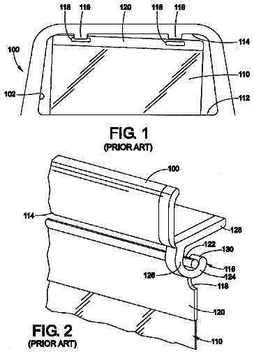
A sunshade hook is provided which has an improved hook shape configuration that overlaps the rod-shaped member of the sunshade to prevent inadvertent pullout.
US 8,579,062 B2 · Assignee: Dr. Ing. h.c. F. Porsche Aktiengesellschaft · Inventors: Niewoehner; Jens et al.
Sheet 1 of 1 from the published document. All sheets in the USPTO PDF
A fuel tank of a motor vehicle is mounted on a body structure of the motor vehicle via fastening elements. The fuel tank has a glass fiber reinforced shaped plastic part (12) as heat shield that at least partially covers a surface of the fuel tank and is mounted with the fuel tank on the body structure of the motor vehicle via the fastening elements.
DE 103 40 952 A1 discloses a motor vehicle with a passenger compartment delimited at the front by a first transverse wall structure and at the rear by a second transverse wall structure. A drive assembly of the motor vehicle is mounted behind the second transverse wall structure. The motor vehicle disclosed in DE 103 40 952 A1 also has a fuel tank fastened to the second rear transverse wall structure by fastener straps. The fuel tank of the motor vehicle of DE 103 40 952 A1 protrudes into the rear part that receives the drive assembly. Thus, the fuel tank is exposed to the heat emitted by the drive assembly. As a result, the fuel tank and the fuel in the fuel tank are heated. Heating fuel is disadvantageous, since heated fuel impairs the degree of efficiency of the drive assembly. The prior art has no simple solutions for preventing the heating of the fuel in the fuel tank. An object of
All 1 drawing sheet from the published document, cropped to the drawing.
What the patent claimed, word for word. All of it is now free to use.
This application claims priority under 35 USC 119 to German Patent Application No 10 2010 016 252.3 filed on Mar. 31, 2010, the entire disclosure of which is incorporated herein by reference.
The invention relates to a fuel tank and to a motor vehicle with a fuel tank.
DE 103 40 952 A1 discloses a motor vehicle with a passenger compartment delimited at the front by a first transverse wall structure and at the rear by a second transverse wall structure. A drive assembly of the motor vehicle is mounted behind the second transverse wall structure. The motor vehicle disclosed in DE 103 40 952 A1 also has a fuel tank fastened to the second rear transverse wall structure by fastener straps. The fuel tank of the motor vehicle of DE 103 40 952 A1 protrudes into the rear part that receives the drive assembly. Thus, the fuel tank is exposed to the heat emitted by the drive assembly. As a result, the fuel tank and the fuel in the fuel tank are heated.
Heating fuel is disadvantageous, since heated fuel impairs the degree of efficiency of the drive assembly. The prior art has no simple solutions for preventing the heating of the fuel in the fuel tank.
An object of the invention is to provide a fuel tank and a motor vehicle with a fuel tank that prevents heating the fuel in the fuel tank.
The invention relates to a fuel tank with a glass fiber reinforced shaped plastic heat shield that at least partially covers and nest with a surface of the fuel tank and, together with the fuel tank, can be mounted on the body structure of the motor vehicle via the fastening elements for the fuel tank.
A glass fiber reinforced shaped plastic part is assigned to the fuel tank as a heat shield. The glass fiber reinforced shaped plastic part covers and nests with a surface of the fuel tank at least partially and, together with the fuel tank, is mounted on the body structure of the motor vehicle via the fastening elements. The glass fiber reinforced shaped plastic part that functions as the heat shield is lightweight and provides a large surface area with sufficient rigidity. Therefore, the shaped plastic heat shield can be mounted on the body structure via the fastening elements that are present in any case for mounting the fuel tank on the body structure of the motor vehicle. As a result, no separate fastening elements are required for mounting the shaped plastic heat shield, thereby ensuring a simple construction.
The glass fiber reinforced shaped plastic part preferably covers and nests with at least a surface of the fuel tank that faces a heat source. Additionally, the surface of the glass fiber reinforced shaped plastic part that faces the heat source preferably is coated metallically. The metallic coating on the surface of the shaped plastic part that faces the heat source increases the heat shield action of the shaped plastic part.
The glass fiber reinforced shaped plastic part preferably has a multiple layer construction, namely a first layer and a second layer made from plastic and a third layer made from glass fiber reinforced plastic positioned between the first and second layers. Either the first layer or the second layer faces the heat source and carries the metallic coating. The multiple layer construction of the shaped plastic part as a sandwich component is advantageous for rigidity.
The shaped plastic part that acts as a heat shield preferably has a contour that is adapted and conforms to the contour of the surface of the fuel tank that is to be covered by the shaped plastic part. This permits a space saving integration of the shaped plastic part that acts as heat shield into the motor vehicle. Tolerances in the fuel tank that occur, for example, during production, can be taken into consideration by a corresponding geometrical allowance in the shaped plastic part.
FIG. 1 is a diagrammatic, cross section of a detail through a fuel tank according to the invention.
FIG. 2 is a schematic cross sectional view of a motor vehicle with a fuel tank in accordance with the invention.
A fuel tank FT of a motor vehicle MV in accordance with the invention has a wall 10 that delimits an inner space 11 of the fuel tank FT. Fuel is provided in the inner space 11 of the fuel tank FT and can be fed to a drive assembly DA of the motor vehicle MV via fuel lines (not shown).
The fuel tank FT of the motor vehicle MV can be mounted on a body structure of the motor vehicle MV via fastening elements FE. The fastening elements are configured as fastener straps, but can be lug-shaped clamping elements.
A fuel tank FT positioned adjacent to the drive assembly DA or adjacent to another heat source, such as an exhaust gas system, necessarily is exposed to great heat due to the heat dissipation of the heat source. As a result, the fuel in the fuel tank FT ultimately is heated. However, fuel preferably is fed at a low temperature to a drive assembly for reasons of efficiency. Thus, heating fuel in the fuel tank FT is not desired.
The invention assigns the fuel tank FT of a motor vehicle a glass fiber reinforced shaped plastic part 12 as heat shield that at least partially covers, nest with and conforms to a surface 13 of the wall 10 of the fuel tank FT.
The glass fiber reinforced shaped plastic part 12 that functions as heat shield preferably covers such a surface 13 of the fuel tank FT that faces a heat source, for example the drive assembly DA, of the motor vehicle.
The shaped plastic part 12 that acts as heat shield reduces heating of the fuel tank FT brought about by convection and/or radiation and therefore reduces heating the fuel in the fuel tank FT. As a result, it is possible to supply a drive assembly with fuel at a lower temperature and thus to increase the degree of efficiency. In addition, the material of the fuel tank FT is protected reliably against excessively high temperatures.
The heat shield that is configured as a glass fiber reinforced shaped plastic part 12 can be mounted, together with the fuel tank FT, on the body structure of the motor vehicle via the fastening elements FE for the fuel tank FT. Accordingly, the heat shield that is configured as a glass fiber reinforced shaped plastic part 12 can be mounted on the body structure of the motor vehicle MV via the fastening elements FE for the fuel tank that are present in any case and preferably are configured as fastener straps or lug-shaped clamping elements. As a result no separate fastening elements are required for mounting the heat shield or shaped plastic part 12.
The heat shield that is configured as a glass fiber reinforced shaped plastic part 12 preferably has a contour that conforms to the contour of the surface 13 of the fuel tank FT that is to be covered by the shaped plastic part 12. As a result, a particularly space saving integration of the heat shield into the motor vehicle MV together with the fuel tank FT is possible.
The glass fiber reinforced shaped plastic part 12 preferably has a multiple layer construction and accordingly preferably is configured as a sandwich component. The glass fiber reinforced shaped plastic part 12 that forms the heat shield preferably has first, second and third layers 14, 15 and 16. The first and second layers 14 and 15 preferably are made from plastic, most preferably from a thermoplastic. The third layer 16 is made from glass fiber reinforced plastic, in particular from glass fiber reinforced thermoplastic, and is positioned between the first and second layers 14 and 15. The thermoplastic preferably is polypropylene.
As described above, the glass fiber reinforced shaped plastic part 12 that functions as heat shield at least partially covers and nest with a surface 13 of the fuel tank FT that faces a heat source. The glass fiber reinforced shaped plastic part 12 is coated metallically, for example with aluminum, on a surface 17 that faces the heat source. Thus, the heat shield action of the shaped plastic part 12 can be increased.
The shaped plastic part 12 preferably is coated with the metallic coating 18 either on the first layer 14 or on the second layer 15, each of which is a thermoplastic, preferably via an aluminum foil that is bonded adhesively to the corresponding surface of the shaped plastic part. In FIG. 2, the metallic coating 18 is applied to the second layer 15 that faces the heat source.
The glass fibers of the glass fiber reinforced shaped plastic part 12 preferably are distributed uniformly as endless fibers and are embedded in the plastic in a nondirectional manner, into the third, middle layer 16 of the shaped plastic part 12 in the exemplary embodiment of FIG. 1.
About 1,545 words. The USPTO PDF has it with every drawing.
Fees are due 3.5, 7.5 and 11.5 years after grant. This patent expired on November 12, 2025, so the fee marked "not paid" was the one that went unpaid.
FUEL TANK
Filed Feb 2011 · published Oct 2011Fuel tank
Filed Feb 2011 · granted Nov 2013Earlier publications, parents and continuations. None of them can still be enforced, or this patent would not be listed.
Prior art cited by the examiner or applicant. Useful when you check your own idea for novelty.
Everything on this page comes from the documents linked above.


