Priority is claimed under 35 U.S.C. .sctn.119 to Japanese Patent Application Nos. 2007-160743 and 2007-160746 filed on Jun. 18, 2007, the disclosure of which incorporated by reference.
Background of the invention
1. Field of invention
The present invention relates to a media processing device for processing media such as CDs and DVDs in a specific way.
2. Description of related art
Media processing devices such as disc duplicators that write data to large numbers of blank CDs, DVDs, and similar media (also referred to as simply "media" below), and CD/DVD publishers that both write the data and print a label to produce finished media, are now widely available. Such media processing devices generally have a drive for writing data to the media, a printer for printing on the label side of the media, and a media transportation mechanism for gripping and conveying the media to the drive and printer. See, for example, Japanese Unexamined Patent Appl. Pub. JP-A-2006-202379.
Media processing devices such as described above have a stacker for storing numerous discs after they have been processed. A door that opens and closes for removing and inserting the stacker is provided at the front of the media processing device. This enables batch processing a large number of discs.
The user may also want to immediately remove a disc when processing is completed. However, if the user opens the access door to remove the processed disc after the media processing device has already started processing the next disc, user contact with other internal parts could cause a problem, and processing is therefore interrupted when the access door opens. Therefore, if the access door is opened to sequentially remove the finished media when a large number of discs are being batch processed, for example, processing is interrupted every time the door is opened. This increases the time required to finish processing all of the media.
In order to allow the user to sequentially remove media and to handle stacker overflow when the processed media stacker is full, another media processing device known from the literature has a media exit that slopes from inside of the media processing device to the outside. The media transportation mechanism can then drop processed media near the media exit so that the media slide down the slope and exit from the media exit. When the processed media stacker becomes full or media are to be removed sequentially, this arrangement enables removing the processed media without opening the access door.
However, when the media are conveyed to the media exit by sliding the media down a slope, the data side of the media can be scratched as the media slide down the slope, or can collide with other previously discharged media, resulting in damage to the data or the label sides of the media.
Demand for an easier way of removing the stacker has also led to drawer-type stackers that can slide horizontally in and out of the media processing device. A frame for guiding the stacker as it slides is incorporated in this type of media processing device. However, if this drawer-type stacker has been pulled out when the media transportation mechanism drops a disc at the stacker position in order to store a completed disc in the processed media stacker, the disc may drop into the gap between the frame and the stacker. If the disc drops into this gap and the stacker drawer is then pushed into the media processing device, the disc may be trapped or damaged, and could lead to mechanical failure of the media processing device.
Summary of the invention
A media processing device according to at least one embodiment of the present invention enables quickly and easily removing finished media without damaging the media.
More particularly, a media processing device according to at least one embodiment of the present invention enables sequentially removing media in the order completed without opening the access door and without damaging the media.
A first aspect of a media processing device according to the present invention has a tray having a stacker for storing media, and a tray holding unit that holds the tray movably between a pulled-out position and a storage position. Alternating land and channel parts are formed on at least part of the opposing surfaces of the tray and the tray holding unit.
This aspect of the invention renders alternating lands and channels that fit and slide together on the opposing surfaces at the top of the tray and the ceiling part of the tray holding unit. There is therefore no gap between the top of the tray and the ceiling part of the tray holding unit, and media will not be trapped between the tray and the tray holding unit when the tray moves. Media will therefore not be trapped and damaged when the tray moves.
Preferably, a channel is formed as the channel part along the direction of tray movement on the surface of the tray facing the tray holding unit, and a protruding part that fits into (matches) said channel is disposed on the surface of the tray holding unit facing the tray.
With this aspect of the invention, the protruding part on the ceiling of the tray holding unit fits into the channel formed in the tray top along the direction of tray movement. As a result, if a disc that could not be stored in the stacker is on top of the tray because the media transportation mechanism dropped a finished disc at the stacker position when the tray was pulled out, the protruding part of the tray holding unit catches the media as the tray moves in to the storage position and thus prevents the disc (media) from entering between the tray and the tray holding unit. Furthermore, because the position of the stacker also moves toward the media caught by the protruding part as the tray moves in, the media is guided so that it slides into and is stored in the stacker.
Yet further preferably, the protruding part disposed on the tray holding unit is disposed on at least one side of the position of the stacker in the direction of tray movement when the tray is housed in the tray holding unit.
With this aspect of the invention, the protruding part is disposed either before or after the stacker in the direction of tray movement when the tray is stored inside the tray holding unit. Therefore, even if media is on top of the tray, moving the tray to the storage position causes the media caught by the protruding part to be guided into the stacker of the tray.
In another aspect of at least one embodiment of the invention the stacker comprises at least one media holding part that holds the outside edge of the media and is formed between the bottom and the open end of the stacker, and the open end of the media holding part of the stacker is larger than the bottom.
With this aspect of the invention, media can be guided along the tapered side wall that widens to the open side of the media holding part of the stacker, and easily stored in the stacker. Furthermore, if the bottom end of the stacker is configured so that media are held by the media holding part with a diameter that is only slightly greater than the outside diameter of the media, the media can be held with effectively no clearance, and the media stacked inside the media holding part will therefore not slide against each other when the tray is pulled out. The media can therefore be held without the surfaces of the media that touch each other being damaged.
Yet further preferably, a first support unit that supports the media in a prescribed area in the center of the media is formed on the bottom of the stacker.
Yet further preferably, the center of the first support unit is recessed and the first support unit is ring-shaped.
With this aspect of the invention, the center of the media at the bottom of the stack in the stacker contacts and is supported stably by the first support unit disposed on the bottom of the stacker. In order to remove the media from the stacker, the user can insert a finger to the recessed part of the first support unit to easily remove the media.
In another aspect of the invention, at least one second support unit positioned at an outside edge surface part of the media is disposed to the bottom of the stacker.
Further preferably, the second support unit is disposed at a position closer to the bottom of the stacker than the first support unit.
This aspect of the invention supports even warped media at the center of the disc at a position outside of the data recording area by the first support unit and at the outside edge area of the media by the media support unit, and can therefore store the media without the second support unit contacting the data recording area or without the second support unit forcefully contacting the data recording area. In addition, if the media enters the stacker at an angle, the media contacts the second support unit and the attitude of the media can be corrected. Furthermore, if the recess in the center part supporting the media is a prescribed height, the media can be easily removed by inserting the fingers and gripping the media.
Further preferably, a media guide part that guides media to the stacker is disposed on the device chassis, the inside diameter of the media guide part on the opposite end of the stacker is greater than the inside diameter of the media guide part at the stacker end, the inside diameter of the end of the stacker open to the media holding part is greater than the inside diameter of the end of the stacker at the media guide part, and the inside diameter of the stacker on the bottom side of the media holding part is substantially equal to the inside diameter of the stacker-side end of the media guide part.
In this aspect of the invention, the media is guided from the large diameter end of the media guide part to the small diameter end, is then discharged from the small diameter bottom end of the media guide part into the large diameter top end of the stacker at the media guide part, and is then guided to the small diameter media holding part at the bottom end of the media holding part of the stacker. As a result, the media can be desirably stored in the media holding part even if the stacker of the tray is at a storage position offset slightly from the media guide part.
Further preferably, the center of the media guide part is on the path of rotation of the media transportation mechanism.
By thus locating the center of the media guide part on the path through which the transportation mechanism pivots at the position where the transportation arm of the transportation mechanism releases the media, the media can be reliably stored at the storage position.
In another aspect of at least one embodiment of the invention, a removal recess is disposed to the bottom part of the stacker.
With this aspect of the invention the media stored in the stacker can also be easily held at the edges and removed without touching the top or bottom surfaces of the media by inserting the fingers to the media access recesses disposed at the bottom of the stacker.
Further preferably, the tray is formed so that the recesses for removing the media are pulled out to the outside when the tray is pulled out from the tray holding unit.
Yet further preferably, a shock absorber is disposed on at least one of a storage limiting part that is disposed on the tray holding unit side and contacts the tray when the tray is stored, and a tray storage stop that is disposed on the tray side and contacts said storage limiting part.
When the tray is closed in this aspect of the invention, the shock absorbers (bumpers) intercede between the tray storage stops of the tray and the storage limiting parts of the tray holding unit. The force of impact when the tray is closed is therefore reduced, and the effect of such impact on the media being processed can be reduced. The quality of media processing can therefore be kept high even if the tray is operated without stopping processing the media.
In another aspect of at least one embodiment of the invention, a shock absorber is disposed on at least one of a pull-out stopping part that is disposed on the tray holding unit side, contacts the tray when the tray is pulled out, and prevents pulling the tray completely out, and a tray pull-out stop that is disposed on the tray side and contacts said pull-out limiting part.
When the tray is pulled out in this aspect of the invention, the shock absorbers intercede between the pull-out stops of the tray and the pull-out stopping parts of the tray holding unit. The force of impact when the tray is pulled out is therefore reduced, and the effect of such impact on the media being processed can be reduced. The quality of media processing can therefore be kept high even if the tray is operated without stopping processing the media.
Another aspect of at least one embodiment of the invention is a media processing device that has a tray having a stacker for storing media, and a tray holding unit that holds the tray movably between a pulled-out position and a storage position. Alternating land and channel parts are formed on at least part of the opposing surfaces of the tray and the tray holding unit, an urging member that pushes toward the side of the tray is disposed on a side part of the tray holding unit, and the side part of the tray that contacts the urging member is sloped so that the width of the tray through said part narrows in the pull-out direction and widens in the storage direction.
This aspect of the invention creates a tapered surface on the side of the tray so that the urging force of the urging member pushes the tray in to the storage position.
With this aspect of the invention, the spring or other urging member disposed to the side of the tray holding unit contacts and applies pressure to the side of the tray so that the tray can be moved without play inside the tray holding unit. The tapered surface disposed in the sliding direction on the side of the tray directs the force of the spring to the inside storage position, and the spring therefore urges the tray to the storage position. The tray can therefore be reliably stored in the storage position and prevented from opening. The media holding parts of the tray can also be easily positioned front-back to the media guide parts.
Preferably, a recess that fits the urging member is disposed at a prescribed position on the side of the tray.
With this aspect of the invention, the recess in the side of the tray engages the spring or other urging member at a prescribed position. This produces a positive click response that tells the user when the recess and the urging member engage and disengage when the tray is pulled out and pushed in. More specifically, the user knows from this engagement click that the tray has reached the end of travel when being pulled out and cannot be pulled out further, or that the tray has reached the end of travel when pushed in, cannot move further, and is positioned in the desired storage position. If the user continues trying to pull the tray out or push the tray in even though it has already been pulled all the way out or pushed all the way in, the tray or tray holding unit could break and excessive vibration or shock could be applied to the media processing device. If media is being processed by one of the drives or printer or is being transported at this time, this vibration or impact could cause an error, degrade the print quality, cause a media picking error or cause the media transportation mechanism to drop the media. With this aspect of the invention, however, the user can operate the tray at the appropriate position and thereby prevent such problems.
Further preferably, a protruding surface part is disposed to the side of the tray that contacts the urging member at a position offset to the end from the middle part of said side.
This protruding surface part disposed offset from the middle towards the inside and/or outside end of the tray increases the sliding resistance imposed by the spring or other urging member. If the tray is opened or closed forcefully, the increased sliding resistance effectively brakes movement and softens the impact. The user can thus know from the increased sliding resistance that the tray is near the inside end or the front outside end.
Yet further preferably, a roller that rolls against the side of the tray is disposed on the urging member.
Because a roller that rotates in the sliding direction of the tray is disposed on the spring or other urging member and contacts the side of the tray, the sliding resistance caused by contact with the urging member can be reduced. Lubrication is therefore not needed, the tray does not become more difficult to slide due to a loss of lubrication, and the user's hand will also not be soiled by lubricating oil.
The media processing device according to at least one embodiment of the invention has a cabinet in which processing units for recording and/or printing media are disposed, and an access door that opens and closes a space inside the cabinet. The media processing device has a tray and a tray holding unit. The tray has a stacker for storing media processed by the processing unit, and can move between a storage position where the tray is stored inside the cabinet and a removal position where the tray is pulled outside the cabinet. The tray holding unit is located inside the cabinet and supports the tray. The tray is located outside of the area through which the access door moves when opening and closing.
This media processing device enables moving the tray supported in the tray holding unit to the storage position, storing media processed inside the cabinet in the stacker, and then pulling the tray out to a media removal position to remove the processed media. Because the tray is outside of the area of the access door, the tray can be pulled out and the media can be removed without opening the door. Furthermore, because the media can be removed without opening the access door, media being processed will not be touched and the quality of the media being processed is not affected. In addition, because the media can be stored in a stacker inside the cabinet, there is no need for the processed media to slide down a slope in order to be discharged to the outside, and the media will therefore not be damaged.
The tray holding unit preferably has a main frame that can be made of sheet metal and a basically U-shaped drawer frame that can also made of sheet metal and is fastened to the tray side of the main frame.
This arrangement results in a tray holding unit that when seen in section view is a closed structure rendered by fastening the sheet metal tray (drawer) frame to the bottom of the sheet metal main frame, thus assuring the rigidity of the tray holding unit.
In another aspect of at least one embodiment of the invention, a plurality of pins separated from each other along the direction in which the tray moves are disposed protruding from the tray holding unit side, and a guide channel into which these pins are inserted is disposed to the tray along the direction of tray movement.
This aspect of the invention enables the movement of the tray in a stable posture because the plurality of pins disposed on the tray holding unit slide along the guide channel when the tray moves.
In another aspect of at least one embodiment of the invention, a low friction sheet is disposed where the tray holding unit and the tray touch.
The low friction sheet disposed on the tray holding unit side in this arrangement reduces sliding friction with the tray, and thus reduces the sliding resistance of the tray.
Another aspect of at least one embodiment of the invention has a tray storage sensor for detecting if the tray is in the storage position.
Because this arrangement enables the detection of whether the tray is in the storage position by means of the tray storage sensor, media handling, such as determining whether processed media can be carried to the stacker or whether processing should be paused, can be changed based on whether or not the tray is in the storage position.
Another aspect of at least one embodiment of the invention has a media sensor that detects the height of the media stack in the stacker.
Because this arrangement enables the detection of the height of the stacked media stored in the stacker by means of this media sensor, storing media above the maximum allowable height in the stacker unit of the tray can also be prevented. Media stacked above the top of the stacker will therefore not interfere with pulling the tray out, and media stacked above the top of the stacker will not be damaged when the tray is pulled out.
Another aspect of at least one embodiment of the invention preferably has an access unit that opens and closes to the outside and disposed on the cabinet of the media processing device where the tray is stored.
If a foreign object somehow gets inside the storage space for the tray, this aspect of the invention enables the easy removal of the foreign object by opening the access unit to the outside. If a foreign object prevents closing of the tray, this arrangement thus enables easily rectifying the problem.
Other objects and attainments together with a fuller understanding of the invention will become apparent and appreciated by referring to the following description and claims taken in conjunction with the accompanying drawings.
Brief description of the drawings
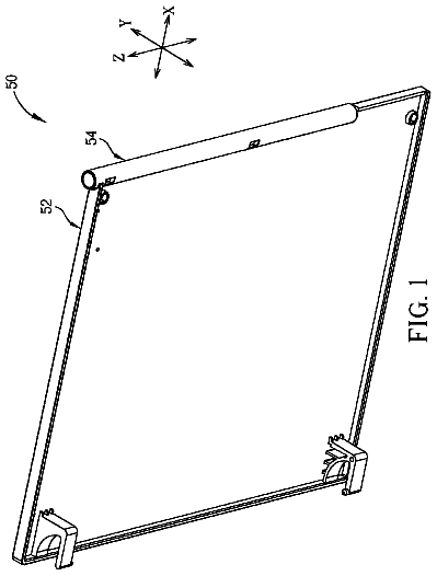
FIG. 1 is an external oblique view of a media publisher (media processing device).
FIG. 2 is an external oblique view of the publisher with the access doors and tray open.
FIG. 3 is an oblique view from the top front side of the publisher with the case removed.
FIG. 4 is an oblique view from the top front side of the publisher with the case removed.
FIG. 5 is an oblique view from the top front side of the publisher with the case removed.
FIG. 6 is an oblique view from the bottom front side of the publisher with the case and part of the drawer mechanism removed.
FIG. 7 is an oblique view from the front top of the publisher with the case removed.
FIG. 8 is an oblique view from the front top of the publisher with the case removed.
FIG. 9 is an oblique view from the bottom front side of the publisher with the case and part of the drawer mechanism removed.
FIG. 10 is an oblique view from the bottom front of the publisher with the case removed.
FIG. 11 is an oblique view of the publisher with only the tray open.
FIG. 12 is an oblique view of the label printer assembly incorporated in the publisher.
FIG. 13 is an oblique view of the main frame.
FIG. 14 is an oblique view of the recessed frame and tray.
FIG. 15 is a frontal view of the tray holding unit.
FIG. 16 is an oblique view of the tray.
FIG. 17 is an oblique view of the tray from a different angle.
FIG. 18 is a plan view showing the tray when stored in the tray holding unit.
FIG. 19 is a plan view of the tray when pulled out from the tray holding unit.
FIG. 20 is a section view showing the stacker unit of the tray and the tubular guide part of the guide member.
FIG. 21 is an oblique view from the back bottom side of the guide member.
FIG. 22 is an oblique view of the guide member.
FIG. 23 is a section view showing the installation of the media full detection sensor.
FIG. 24 is an enlarged view showing the operation of the tray storage sensor.
FIG. 25 is an oblique view from the back of the publisher.
FIG. 26 is an oblique view from the back of the publisher.
FIG. 27 is an oblique view of the media stacker.
FIG. 28 is an oblique view of the media stacker.
FIG. 29 is an oblique view of the media stacker.
FIG. 30 is a section view of the media stacker.
Description of preferred embodiments
A preferred embodiment of a media processing device according to the present invention is described below with reference to the accompanying figures.
The media processing device of the invention is described below using a media publisher by way of example.
FIG. 1 is an external oblique view of a media publisher (media processing device) when all units are closed.
As shown in FIG. 1, the publisher 1 is a media processing device that writes data and prints on the label side of disc-shaped media such as CDs and DVDs, and has a basically box-shaped case 2. Doors 3 and 4 that open and close to the right and left are attached at the front of the case 2. An operating panel 5 having various indicators and operating buttons is disposed at the top left part of the case 2, and support legs 6 project down from the bottom of the case 2 on both right and left sides. A drawer mechanism 7 is disposed between the right and left legs 6.
The access door 3 on the front right side opens and closes for access to an open area 8 at the front of the publisher 1. The access door 3 is opened and closed for loading unused (blank) media M and removing finished media M from the open area 8.
The access door 4 on the front left side opens and closes for replacing the ink cartridges 12 of the label printer 11 shown in FIG. 3. When the door 4 is open, a cartridge carrier unit 14 with a plurality of cartridge holders 13 arrayed in a vertical stack is exposed.
A media stacker 21 (media storage unit) for holding a plurality of unused blank discs M (such as 50) to which data has not been written in a vertical stack, and a second media stacker 22 for similarly holding a plurality of completed discs M or blank discs M (such as 50) are disposed inside the case 2 of the publisher 1. The blank media stacker 21 and the completed media stacker 22 can be freely installed to and removed from the positions shown in FIG. 2. Media stacker 21 and media stacker 22 are disposed one above the other so that the media M are stored coaxially in the stackers. Both media stacker 21 and media stacker 22 can be freely installed to and removed from predetermined positions.
The top media stacker 21 has a pair of right and left cylindrical side walls 24 and 25. The blank discs M are placed from the top into the blank media stacker 21 between the side walls 24 and 25, which hold the discs in a substantially coaxial stack. The task of storing or adding the blank discs M to the blank media stacker 21 can be done easily by opening the door 3 and pulling the media stacker 21 out.
The bottom media stacker 22 is identically constructed with a pair of right and left curved side walls 27 and 28, enabling the discs M to be inserted from the top and stored in a substantially coaxial stack.
A media transportation mechanism 31 is located behind the media stackers 21 and 22. The media transportation mechanism 31 has a vertical guide shaft 35 disposed between the main frame 30 and the top plate 33 of the chassis 32. A transportation arm 36 is supported so that it can move up and down and rotate on the vertical guide shaft 35. The transportation arm 36 can move vertically up and down along the vertical guide shaft 35 and can pivot right and left on the vertical guide shaft 35 by means of a drive motor 37.
Two media drives 41 are disposed one above the other beside the two stackers 21 and 22 and the media transportation mechanism 31, and the label printer 11 is disposed below the media drives 41.
Each of the media drives 41 has a media tray 41a, which can move between a data writing position where data is recorded to the discs, and a media transfer position where the media can be loaded and unloaded from the media tray 41a.
The label printer 111 also has a media tray 45 that can move between a printing position for printing a label on the label side of the media M, and a media transfer position where the media can be loaded and unloaded from the media tray 45.
FIG. 3 shows the media trays 41a of the top and bottom media drives 41 pulled out to the media transfer position, and the media tray 45 of the label printer 11 at the media transfer position.
The label printer 11 in this example is an inkjet printer that uses color ink cartridges 12 (for six colors, specifically, black, cyan, magenta, yellow, light cyan, and light magenta) as the ink supply mechanism 60. The ink cartridges 12 are installed from the front to the individual cartridge holders 13 of the cartridge carrier unit 14.
A space enabling the transportation arm 36 of the media transportation mechanism 31 to move up and down is formed between the pair of right and left side walls 24 and 25 of the first media stacker 21 and between the pair of right and left side walls 27 and 28 of the second media stacker 22. A space is also formed between the top and bottom media stackers 21 and 22 so that the transportation arm 36 of the media transportation mechanism 31 can pivot horizontally for positioning directly above the bottom media stacker 22. When media trays 41a are pushed into the media drives 41, the transportation arm 36 of the media transportation mechanism 31 descends and can access the media tray 45 of the label printer 11 at the media transfer position.
When both media trays 41a are in the data writing position and the media tray 45 for the label printer 11 is at the inside printing position, the transportation arm 36 of the media transportation mechanism 31 can descend below the height of the printer media tray 45. A guide hole 65 (see FIG. 2) further described below is below the media transfer position of the printer media tray 45, and the transportation arm 36 can descend to this position.
The guide hole 65 is a hole that allows the transportation arm 36 to descend and release a disc M so that the disc passes through the guide hole 65. A separate media stacker further described below can also be installed in this guide hole 65.
As shown in FIG. 2, the drawer mechanism 7 has a tray 70 disposed below the main frame 30 so that the tray 70 can slide into and out of the main frame 30. The tray 70 has a recess in which a stacker unit 71 can store the media M. When this tray 70 is in the stored (closed) position, the stacker unit 71 is positioned below the guide hole 65, and the center of the stacker unit 71 is positioned with the center of the stacker unit 71 coaxial to the center axis of the media trays 41a and the printer media tray 45 in the media transfer position. The stacker unit 71 accepts media M guided thereinto by the guide hole 65 on the main frame 30 side, and stores a relatively small number of media M (such as 5 to 10). The stacker unit 71 accepts the media M from the open side and stores the media M stacked coaxially from the bottom of the stacker.
A different media stacker 72 (removable media stacker) that can hold more media M than the stacker unit 71 is removably disposed in the guide hole 65 (see FIG. 3). This media stacker 72 also has two curved side walls 73 and 74. Media M can be loaded from the open top between the side walls 73 and 74, and a plurality of media M (such as 50) can be stored coaxially in a stack from the bottom of the media stacker 72. A gap enabling the transportation arm 36 of the media transportation mechanism 31 to move up and down is also formed between the pair of curved side walls 73 and 74. A handle 75 that is held by the user when installing and removing the media stacker 72 is disposed at the top part of the one side wall 74.
When the media stacker 72 is installed as shown in FIG. 4 to FIG. 7, a blank disc M is taken from the bottom media stacker 22, written and printed by a media drive 41 and the label printer 11, and then deposited in the media stacker 72.
When both the top media stacker 21 and the bottom media stacker 22 are loaded to capacity (50 discs each in this embodiment of the invention) with blank media M, all media M
in the bottom media stacker 22 are sequentially processed and stored in the media stacker 72, and all media M
in the top media stacker 21 are then sequentially processed and stored in the emptied bottom media stacker 22. This enables batch processing the maximum number of media M (50+50) that can be loaded in the top media stacker 21 and the bottom media stacker 22 in a single operation (the "batch processing mode").
As shown in FIG. 8 to FIG. 10, when the media stacker 72 is removed, a blank disc M can be removed from the top media stacker 21 or the bottom media stacker 22, the disc can be written and printed by the media drive 41 and label printer 11, the completed disc can be stored in the stacker unit 71 of the tray 70 in the stored (closed) position, and the tray 70 can be pulled out to remove the disc(s).
The tray 70 can be pulled out as shown in FIG. 11 so that the completed media M can be removed from the stacker unit 71. More specifically, completed media M can be sequentially removed one by one or plural discs at a time while processing other media M continues and the access door 3 remains closed. This is also referred to herein as the "external discharge mode."
The transportation arm 36 of the media transportation mechanism 31 can thus grip and release media M, and the transportation arm 36 can move up and down and pivot right and left in various combinations of motions to access different positions. As a result, the media transportation mechanism 31 can carry media M between the top media stacker 21, the bottom media stacker 22, the stacker unit 71 (or media stacker 72) of the tray 70, the media trays 41a of the media drives 41, and the printer media tray 45 of the label printer 11.
As shown in FIG. 12, the label printer 11 has a carriage 62 with an inkjet head 61 having nozzles (not shown in the figure) for discharging ink. The carriage 62 moves bidirectionally horizontally along a carriage guide shaft (not shown in the figure) by means of the drive power from a carriage motor (not shown in the figure).
The label printer 11 has an ink supply mechanism 60 with a cartridge carrier unit 14 in which the ink cartridges 12 are installed. The ink supply mechanism 60 is vertically constructed and is attached perpendicularly to the main frame 30 of the publisher 1. One end of a flexible ink supply tube 63 is connected to the ink supply mechanism 60, and the other end of the ink supply tube 63 is connected to the carriage 62.
Ink in the ink cartridges 12 loaded in the ink supply mechanism 60 is supplied through the ink supply tube 63 to the carriage 62. The ink is supplied to the inkjet head 61 through the damper unit and back pressure adjustment unit (not shown in the figure) disposed to the carriage 62, and discharged from the ink nozzles (not shown in the figure).
A pressurizing mechanism 64, which is disposed to the top of the ink supply mechanism 60, supplies compressed air to pressurize the inside of the ink cartridge 12 and expels ink from the ink pack in the ink cartridge 12.
A head maintenance mechanism 81 is disposed below the home position (shown in FIG. 12) of the carriage 62.
The head maintenance mechanism 81 has a head cap 82 and a waste ink suction pump 83. The head cap 82 covers the ink nozzles of the inkjet head 61 exposed below the carriage 62 in the home position. The waste ink suction pump 83 vacuums ink discharged into the head cap 82 by the ink charging operation and the head cleaning operation of the inkjet head 61.
Ink that is removed by the waste ink suction pump 83 of the head maintenance mechanism 81 is discharged through another tube 84 into the waste ink absorption tank 85. This waste ink absorption tank 85 is an absorbent material not shown that is disposed inside the case 86, and has a cover 88 with numerous ventilation holes 87.
A waste ink catch pan 89 that is a part of the waste ink absorption tank 85 is disposed below the head maintenance mechanism 81 to catch and absorb ink that drips from the head maintenance mechanism 81 with an absorbent material.
A control unit not shown that controls the publisher 1 determines if the doors 3 and 4 are open or closed based on a detection signal from a door sensor not shown. If either of the doors 3 and 4 opens while the media transportation mechanism 31 or label printer 11 is operating, the control unit stops the media M transportation operation, the data writing operation of the media drive 41, and the printing operation of the label printer 11. More specifically, both media M printing and transportation operations are restricted when a door is open. Operation resumes when both doors 3 and 4 are closed.
The drawer mechanism 7 and surrounding parts are described next.
FIG. 13 is an oblique view of the main frame. FIG. 14 is an oblique view of the recessed frame and tray. FIG. 15 is a frontal view of the tray holding unit. FIG. 16 and FIG. 17 are oblique views of the tray. FIG. 18 is a plan view showing the tray when stored in the tray holding unit. FIG. 19 is a plan view of the tray when pulled out from the tray holding unit. FIG. 20 is a section view showing the stacker unit of the tray and the cylindrical guide part of the guide member. FIG. 21 is an oblique view from the back bottom side of the guide member. FIG. 22 is an oblique view of the guide member. FIG. 23 is a section view showing the installation of the media full detection sensor. FIG. 24 is an enlarged view showing the operation of the tray storage sensor. FIG. 25 and FIG. 26 are oblique views of the publisher from the back.
As shown in FIG. 13 and FIG. 14, the drawer mechanism 7 includes a sheet metal main frame 30 and a recessed drawer frame 91 that is also made of sheet metal and is fastened to the bottom of the main frame 30.
The drawer frame 91 is a recessed frame composed of a bottom panel 92, a pair of side walls 93 and a pair of attachment rails 94. The side walls 93 rise perpendicularly from the right and left edges of the bottom panel 92. The attachment rails 94 extend in mutually opposite directions from the top edges of the side walls 93. The drawer frame 91 also has a pair of stops 96 (storage limiting parts) that extend in mutually opposite directions from the front ends of the side walls 93. The curved parts of the side walls 93 and stops 96 are bent in an arc, rendering a curved border part 95.
As shown in FIG. 15, the drawer frame 91 is fastened to the main frame 30 with the attachment rails 94 against the bottom of the main frame 30. The main frame 30 and drawer frame 91 thus form a tray holding unit 98 that supports the tray 70 so that the tray 70 can slide in and out.
The tray holding unit 98 and the tray 70 held therein are thus disposed in a location outside of the area used by the access door 3 to open and close above the main frame 30. The stacker unit 71 disposed on the tray 70 is also located below the bottom of the main frame 30. The tray 70 is also protected from scratching and marring when sliding in an out because the transition between the side walls 93 and the stops 96 is the curved border part 95.
A plastic low friction sheet 114 that reduces sliding friction with the bottom of the tray 70 is adhesively attached along both right and left sides of the top of the bottom panel 92 of the drawer frame 91 part of the tray holding unit 98. The low friction sheets 114 extend lengthwise in the direction that the tray 70 slides, and similar low friction sheets 115 that reduce sliding friction with the top of the tray 70 are adhesively attached to the bottom on the right and left sides of the main frame 30 part of the tray holding unit 98.
The description continues in the full USPTO document.
 Lapsed, fee not paid56 drawings