Background
1.
Field
The present disclosure relates to zoom lens systems, imaging devices and cameras.
2. Description of the related art
Cameras including an image sensor for performing photoelectric conversion, such as digital still cameras and digital video cameras, have been required to have high resolution, and particularly in recent years, these cameras have been strongly required to have a reduced thickness, a relatively high zooming ratio, and capability of compensating various aberrations. For example, various kinds of zoom lens systems have been proposed, each having a three-or-more unit configuration of positive, negative, and positive, or positive, negative, and negative, in which a first lens unit having positive optical power, a second lens unit having negative optical power, a third lens unit having positive or negative optical power, and a subsequent lens unit are arranged in order from an object side to an image side. Hereinafter, the cameras including an image sensor for performing photoelectric conversion, such as digital still cameras and digital video cameras, are simply referred to as "digital cameras".
Japanese Laid-Open Patent Publications Nos. 2009-282429, 2009-115875, 2009-086437, and 2008-304708 each disclose a zoom lens having the three-or-more unit configuration of positive, negative, and positive.
Japanese Laid-Open Patent Publication No. 2008-281927 discloses a variable-magnification optical system having the three-or-more unit configuration of positive, negative, and positive.
Japanese Laid-Open Patent Publication No. 2007-047538 discloses an imaging optical system having the three-or-more unit configuration of positive, negative, and positive, or positive, negative, and negative.
Japanese Laid-Open Patent Publication No. 2001-350093 discloses an imaging lens device equipped with a zoom lens system having the three-or-more unit configuration of positive, negative, and positive.
Summary
The present disclosure provides: a high-performance and thin zoom lens system that has, as well as high resolution, a relatively high zooming ratio, but has less aberration fluctuation in zooming; an imaging device employing the zoom lens system; and a thin and compact camera employing the imaging device.
The novel concepts disclosed herein were achieved in order to solve the foregoing problems in the related art, and herein is disclosed:
a zoom lens system, in order from an object side to an image side, comprising:
a first lens unit having positive optical power;
a second lens unit having negative optical power;
a third lens unit having positive optical power; and
one or more subsequent lens units, wherein
in zooming from a wide-angle limit to a telephoto limit at the time of image taking, the first lens unit, the second lens unit, and the third lens unit are moved along an optical axis to perform magnification change,
a lens unit .alpha. which is one of the subsequent lens units does not move along the optical axis at the time of the zooming, but moves along the optical axis at the time of transition from an imaging state to an accommodated state, and
the following conditions (1), (2-1) and (a) are satisfied: 0.8<L.sub.T/f.sub.T<1.2
0.12<D.sub..alpha./f.sub.G.alpha.<0.30 (2-1) f.sub.T/f.sub.W>9.0 (a)
where,
L.sub.T is an overall length of lens system (a distance from a most object side surface of the first lens unit to an image surface) at a telephoto limit,
D.sub..alpha. is an axial air-equivalent length between a most image side surface of the lens unit .alpha. and the image surface,
f.sub.G.alpha. is a composite focal length of the lens unit .alpha.,
f.sub.W is a focal length of the entire system at a wide-angle limit, and
f.sub.T is a focal length of the entire system at a telephoto limit.
The novel concepts disclosed herein were achieved in order to solve the foregoing problems in the related art, and herein is disclosed:
an imaging device capable of outputting an optical image of an object as an electric image signal, comprising:
a zoom lens system that forms the optical image of the object; and
an image sensor that converts the optical image formed by the zoom lens system into the electric image signal, wherein
the zoom lens system is a zoom lens system, in order from an object side to an image side, comprising:
a first lens unit having positive optical power;
a second lens unit having negative optical power;
a third lens unit having positive optical power; and
one or more subsequent lens units, wherein
in zooming from a wide-angle limit to a telephoto limit at the time of image taking, the first lens unit, the second lens unit, and the third lens unit are moved along an optical axis to perform magnification change,
a lens unit .alpha. which is one of the subsequent lens units does not move along the optical axis at the time of the zooming, but moves along the optical axis at the time of transition from an imaging state to an accommodated state, and
the following conditions (1), (2-1) and (a) are satisfied: 0.8<L.sub.T/f.sub.T<1.2
0.12<D.sub..alpha./f.sub.G.alpha.<0.30 (2-1) f.sub.T/f.sub.W>9.0 (a)
where,
L.sub.T is an overall length of lens system (a distance from a most object side surface of the first lens unit to an image surface) at a telephoto limit,
D.sub..alpha. is an axial air-equivalent length between a most image side surface of the lens unit .alpha. and the image surface,
f.sub.G.alpha. is a composite focal length of the lens unit .alpha.,
f.sub.W is a focal length of the entire system at a wide-angle limit, and
f.sub.T is a focal length of the entire system at a telephoto limit.
The novel concepts disclosed herein were achieved in order to solve the foregoing problems in the related art, and herein is disclosed:
a camera for converting an optical image of an object into an electric image signal, and performing at least one of displaying and storing of the converted image signal, comprising:
an imaging device including a zoom lens system that forms the optical image of the object, and an image sensor that converts the optical image formed by the zoom lens system into the electric image signal, wherein
the zoom lens system is a zoom lens system, in order from an object side to an image side, comprising:
a first lens unit having positive optical power;
a second lens unit having negative optical power;
a third lens unit having positive optical power; and
one or more subsequent lens units, wherein
in zooming from a wide-angle limit to a telephoto limit at the time of image taking, the first lens unit, the second lens unit, and the third lens unit are moved along an optical axis to perform magnification change,
a lens unit .alpha. which is one of the subsequent lens units does not move along the optical axis at the time of the zooming, but moves along the optical axis at the time of transition from an imaging state to an accommodated state, and
the following conditions (1), (2-1) and (a) are satisfied: 0.8<L.sub.T/f.sub.T<1.2
0.12<D.sub..alpha./f.sub.G.alpha.<0.30 (2-1) f.sub.T/f.sub.W>9.0 (a)
where,
L.sub.T is an overall length of lens system (a distance from a most object side surface of the first lens unit to an image surface) at a telephoto limit,
D.sub..alpha. is an axial air-equivalent length between a most image side surface of the lens unit .alpha. and the image surface,
f.sub.G.alpha. is a composite focal length of the lens unit .alpha.,
f.sub.W is a focal length of the entire system at a wide-angle limit, and
f.sub.T is a focal length of the entire system at a telephoto limit.
A zoom lens system in the present disclosure is a high-performance and thin zoom lens system that has, as well as high resolution, a relatively high zooming ratio, but has less aberration fluctuation in zooming. An imaging device in the present disclosure employs the zoom lens system, and a camera employing the imaging device is thin and compact.
Brief description of the drawings
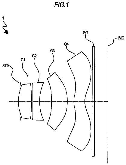
This and other objects and features of the present disclosure will become clear from the following description, taken in conjunction with the exemplary embodiments with reference to the accompanied drawings in which:
FIG. 1 is a lens arrangement diagram showing an infinity in-focus condition of a zoom lens system according to Embodiment 1 (Numerical Example 1);
FIG. 2 is a longitudinal aberration diagram of an infinity in-focus condition of a zoom lens system according to Numerical Example 1;
FIG. 3 is a lateral aberration diagram of a zoom lens system according to Numerical Example 1 at a telephoto limit in a basic state where image blur compensation is not performed and in an image blur compensation state;
FIG. 4 is a lens arrangement diagram showing an infinity in-focus condition of a zoom lens system according to Embodiment 2 (Numerical Example 2);
FIG. 5 is a longitudinal aberration diagram of an infinity in-focus condition of a zoom lens system according to Numerical Example 2;
FIG. 6 is a lateral aberration diagram of a zoom lens system according to Numerical Example 2 at a telephoto limit in a basic state where image blur compensation is not performed and in an image blur compensation state;
FIG. 7 is a lens arrangement diagram showing an infinity in-focus condition of a zoom lens system according to Embodiment 3 (Numerical Example 3);
FIG. 8 is a longitudinal aberration diagram of an infinity in-focus condition of a zoom lens system according to Numerical Example 3;
FIG. 9 is a lateral aberration diagram of a zoom lens system according to Numerical Example 3 at a telephoto limit in a basic state where image blur compensation is not performed and in an image blur compensation state;
FIG. 10 is a lens arrangement diagram showing an infinity in-focus condition of a zoom lens system according to Embodiment 4 (Numerical Example 4);
FIG. 11 is a longitudinal aberration diagram of an infinity in-focus condition of a zoom lens system according to Numerical Example 4;
FIG. 12 is a lateral aberration diagram of a zoom lens system according to Numerical Example 4 at a telephoto limit in a basic state where image blur compensation is not performed and in an image blur compensation state;
FIG. 13 is a lens arrangement diagram showing an infinity in-focus condition of a zoom lens system according to Embodiment 5 (Numerical Example 5);
FIG. 14 is a longitudinal aberration diagram of an infinity in-focus condition of a zoom lens system according to Numerical Example 5;
FIG. 15 is a lateral aberration diagram of a zoom lens system according to Numerical Example 5 at a telephoto limit in a basic state where image blur compensation is not performed and in an image blur compensation state;
FIG. 16 is a lens arrangement diagram showing an infinity in-focus condition of a zoom lens system according to Embodiment 6 (Numerical Example 6);
FIG. 17 is a longitudinal aberration diagram of an infinity in-focus condition of a zoom lens system according to Numerical Example 6;
FIG. 18 is a lateral aberration diagram of a zoom lens system according to Numerical Example 6 at a telephoto limit in a basic state where image blur compensation is not performed and in an image blur compensation state;
FIG. 19 is a lens arrangement diagram showing an infinity in-focus condition of a zoom lens system according to Embodiment 7 (Numerical Example 7);
FIG. 20 is a longitudinal aberration diagram of an infinity in-focus condition of a zoom lens system according to Numerical Example 7;
FIG. 21 is a lateral aberration diagram of a zoom lens system according to Numerical Example 7 at a telephoto limit in a basic state where image blur compensation is not performed and in an image blur compensation state; and
FIG. 22 is a schematic configuration diagram of a digital still camera according to Embodiment 8.
Detailed description
Hereinafter, embodiments will be described with reference to the drawings as appropriate. However, descriptions more detailed than necessary may be omitted. For example, detailed description of already well known matters or description of substantially identical configurations may be omitted. This is intended to avoid redundancy in the description below, and to facilitate understanding of those skilled in the art.
It should be noted that the applicant provides the attached drawings and the following description so that those skilled in the art can fully understand this disclosure. Therefore, the drawings and description are not intended to limit the subject defined by the claims.
Embodiments 1 to 7
FIGS. 1, 4, 7, 10, 13, 16 and 19 are lens arrangement diagrams of zoom lens systems according to Embodiments 1 to 7, respectively.
Each of FIGS. 1, 4, 7, 10, 13, 16 and 19 shows a zoom lens system in an infinity in-focus condition. In each Fig., part (a) shows a lens configuration at a wide-angle limit, part (b) shows a lens configuration at a middle position, and part (c) shows a lens configuration at a telephoto limit. The wide-angle limit is the minimum focal length condition, and the focal length is expressed by f.sub.W. The middle position is an intermediate focal length condition, and the focal length is expressed by f.sub.M= (f.sub.W*f.sub.T). The telephoto limit is the maximum focal length condition, and the focal length is expressed by f.sub.T. Further, in each Fig., each bent arrow provided between part (a) and part (b) indicates a line obtained by connecting the positions of each lens unit at a wide-angle limit, a middle position and a telephoto limit in order from the top. Accordingly, in the part between the wide-angle limit and the middle position, and the part between the middle position and the telephoto limit, the positions are connected simply with a straight line, and this line does not indicate an actual motion of each lens unit. Furthermore, in each Fig., an arrow imparted to a lens unit indicates focusing from an infinity in-focus condition to a close-object in-focus condition. That is, in FIGS. 1, 4, 7, 10, 13 and 16, the arrow indicates the direction in which a fourth lens unit G4 described later moves in focusing from the infinity in-focus condition to the close-object in-focus condition. In FIG. 19, the arrow indicates the direction in which a third lens unit G3 described later moves in focusing from the infinity in-focus condition to the close-object in-focus condition.
Each of the zoom lens systems according to Embodiments 1 to 6, in order from the object side to the image side, comprises: a first lens unit G1 having positive optical power; a second lens unit G2 having negative optical power; a third lens unit G3 having positive optical power; a fourth lens unit G4 having negative optical power; and a fifth lens unit G5 having positive optical power. The zoom lens system according to Embodiment 7, in order from the object side to the image side, comprises: a first lens unit G1 having negative optical power; a second lens unit G2 having positive optical power; a third lens unit G3 having positive optical power; and a fourth lens unit G4 having positive optical power.
In the zoom lens systems according to Embodiments 1 to 6, in zooming, the first lens unit G1, the second lens unit G2, the third lens unit G3, and the fourth lens unit G4 move in a direction along the optical axis such that the intervals between the respective lens units, that is, the interval between the first lens unit G1 and the second lens unit G2, the interval between the second lens unit G2 and the third lens unit G3, the interval between the third lens unit G3 and the fourth lens unit G4, and the interval between the fourth lens unit G4 and the fifth lens unit G5 vary. In the zoom lens system according to Embodiment 7, in zooming, the first lens unit G1, the second lens unit G2, and the third lens unit G3 move in the direction along the optical axis such that the intervals between the respective lens units, that is, the interval between the first lens unit G1 and the second lens unit G2, the interval between the second lens unit G2 and the third lens unit G3, and the interval between the third lens unit G3 and the fourth lens unit G4 vary. In the zoom lens system according to each embodiment, by arranging the lens units in a desired optical power configuration, size reduction in the entire lens system is achieved while maintaining high optical performance.
In FIGS. 1, 4, 7, 10, 13, 16 and 19, an asterisk "*" imparted to a particular surface indicates that the surface is aspheric. In each Fig., symbol (+) or (-) imparted to the symbol of each lens unit corresponds to the sign of the optical power of the lens unit. In each Fig., the straight line located on the most right-hand side indicates the position of the image surface S. On the object side relative to the image surface S, i.e., between the image surface S and the most image side lens surface in the fifth lens unit G5 in FIGS. 1, 4, 7, 10, 13 and 16, or between the image surface S and the most image side lens surface in the fourth lens unit G4 in FIG. 19, a plane parallel plate P equivalent to an optical low-pass filter or a face plate of an image sensor is provided.
Embodiment 1
As shown in FIG. 1, the first lens unit G1, in order from the object side to the image side, comprises: a negative meniscus first lens element L1 with the convex surface facing the object side; a positive meniscus second lens element L2 with the convex surface facing the object side; and a positive meniscus third lens element L3 with the convex surface facing the object side. Among these, the first lens element L1 and the second lens element L2 are cemented with each other. In the surface data of the corresponding Numerical Example described later, surface number 2 is imparted to an adhesive layer between the first lens element L1 and the second lens element L2.
The second lens unit G2, in order from the object side to the image side, comprises: a negative meniscus fourth lens element L4 with the convex surface facing the object side; a negative meniscus fifth lens element L5 with the convex surface facing the image side; and a bi-convex sixth lens element L6. Among these, the fourth lens element L4 has two aspheric surfaces.
The third lens unit G3, in order from the object side to the image side, comprises: a bi-convex seventh lens element L7; a bi-convex eighth lens element L8, a bi-concave ninth lens element L9; and a bi-convex tenth lens element L10. Among these, the eighth lens element L8 and the ninth lens element L9 are cemented with each other. In the surface data of the corresponding Numerical Example described later, surface number 16 is imparted to an adhesive layer between the eighth lens element L8 and the ninth lens element L9. The seventh lens element L7 has two aspheric surfaces.
The fourth lens unit G4 comprises solely a negative meniscus eleventh lens element L11 with the convex surface facing the object side.
The fifth lens unit G5 comprises solely a bi-convex twelfth lens element L12. The twelfth lens element L12 has two aspheric surfaces.
In the zoom lens system according to Embodiment 1, an aperture diaphragm A is provided between the third lens unit G3 and the fourth lens unit G4. In zooming from a wide-angle limit to a telephoto limit at the time of image taking, the aperture diaphragm A moves along the optical axis to the object side, integrally with the third lens unit G3.
In the zoom lens system according to Embodiment 1, a plane parallel plate P is provided on the object side relative to the image surface S, i.e., between the image surface S and the twelfth lens element L12.
In the zoom lens system according to Embodiment 1, in zooming from a wide-angle limit to a telephoto limit at the time of image taking, the first lens unit G1 and the fourth lens unit G4 move nearly monotonically to the object side, the second lens unit G2 moves to the image side with locus of a convex to the image side, the third lens unit G3 moves monotonically to the object side, and the fifth lens unit G5 is fixed with respect to the image surface S. That is, in zooming, the first lens unit G1, the second lens unit G2, the third lens unit G3, and the fourth lens unit G4 move along the optical axis such that the interval between the first lens unit G1 and the second lens unit G2 increases, the interval between the second lens unit G2 and the third lens unit G3 decreases, the interval between the third lens unit G3 and the fourth lens unit G4 changes, and the interval between the fourth lens unit G4 and the fifth lens unit G5 increases.
As described above, the fifth lens unit G5 is a lens unit that does not move along the optical axis at the time of zooming but moves along the optical axis at the time of transition from the imaging state to the accommodated state, and corresponds to a lens unit .alpha. which is one of subsequent lens units described later.
In the zoom lens system according to Embodiment 1, in focusing from an infinity in-focus condition to a close-object in-focus condition, the fourth lens unit G4 moves along the optical axis to the image side.
Embodiment 2
As shown in FIG. 4, the first lens unit G1, in order from the object side to the image side, comprises: a negative meniscus first lens element L1 with the convex surface facing the object side; a positive meniscus second lens element L2 with the convex surface facing the object side; and a positive meniscus third lens element L3 with the convex surface facing the object side. Among these, the first lens element L1 and the second lens element L2 are cemented with each other. In the surface data of the corresponding Numerical Example described later, surface number 2 is imparted to an adhesive layer between the first lens element L1 and the second lens element L2.
The second lens unit G2, in order from the object side to the image side, comprises: a negative meniscus fourth lens element L4 with the convex surface facing the object side; a bi-concave fifth lens element L5; and a bi-convex sixth lens element L6. Among these, the fourth lens element L4 has two aspheric surfaces.
The third lens unit G3, in order from the object side to the image side, comprises: a bi-convex seventh lens element L7; a positive meniscus eighth lens element L8 with the convex surface facing the object side; a negative meniscus ninth lens element L9 with the convex surface facing the object side; and a bi-convex tenth lens element L10. Among these, the eighth lens element L8 and the ninth lens element L9 are cemented with each other. In the surface data of the corresponding Numerical Example described later, surface number 16 is imparted to an adhesive layer between the eighth lens element L8 and the ninth lens element L9. The seventh lens element L7 has two aspheric surfaces.
The fourth lens unit G4 comprises solely a negative meniscus eleventh lens element L11 with the convex surface facing the object side.
The fifth lens unit G5 comprises solely a bi-convex twelfth lens element L12. The twelfth lens element L12 has two aspheric surfaces.
In the zoom lens system according to Embodiment 2, an aperture diaphragm A is provided between the third lens unit G3 and the fourth lens unit G4. In zooming from a wide-angle limit to a telephoto limit at the time of image taking, the aperture diaphragm A moves along the optical axis to the object side, integrally with the third lens unit G3.
In the zoom lens system according to Embodiment 2, a plane parallel plate P is provided on the object side relative to the image surface S, i.e., between the image surface S and the twelfth lens element L12.
In the zoom lens system according to Embodiment 2, in zooming from a wide-angle limit to a telephoto limit at the time of image taking, the first lens unit G1 moves to the object side with locus of a convex to the image side, the second lens unit G2 moves to the image side with locus of a convex to the image side, the third lens unit G3 moves nearly monotonically to the object side, the fourth lens unit G4 moves monotonically to the object side, and the fifth lens unit G5 is fixed with respect to the image surface S. That is, in zooming, the first lens unit G1, the second lens unit G2, the third lens unit G3, and the fourth lens unit G4 move along the optical axis such that the interval between the first lens unit G1 and the second lens unit G2 increases, the interval between the second lens unit G2 and the third lens unit G3 decreases, the interval between the third lens unit G3 and the fourth lens unit G4 changes, and the interval between the fourth lens unit G4 and the fifth lens unit G5 increases.
As described above, the fifth lens unit G5 is a lens unit that does not move along the optical axis at the time of zooming but moves along the optical axis at the time of transition from the imaging state to the accommodated state, and corresponds to a lens unit .alpha. which is one of subsequent lens units described later.
In the zoom lens system according to Embodiment 2, in focusing from an infinity in-focus condition to a close-object in-focus condition, the fourth lens unit G4 moves along the optical axis to the image side.
Embodiment 3
As shown in FIG. 7, the first lens unit G1, in order from the object side to the image side, comprises: a negative meniscus first lens element L1 with the convex surface facing the object side; a bi-convex second lens element L2; and a positive meniscus third lens element L3 with the convex surface facing the object side. Among these, the first lens element L1 and the second lens element L2 are cemented with each other. In the surface data of the corresponding Numerical Example described later, surface number 2 is imparted to an adhesive layer between the first lens element L1 and the second lens element L2.
The second lens unit G2, in order from the object side to the image side, comprises: a negative meniscus fourth lens element L4 with the convex surface facing the object side; a negative meniscus fifth lens element L5 with the convex surface facing the image side; and a bi-convex sixth lens element L6. Among these, the fourth lens element L4 has two aspheric surfaces.
The third lens unit G3, in order from the object side to the image side, comprises: a bi-convex seventh lens element L7; a positive meniscus eighth lens element L8 with the convex surface facing the object side; a negative meniscus ninth lens element L9 with the convex surface facing the object side; and a bi-convex tenth lens element L10. Among these, the eighth lens element L8 and the ninth lens element L9 are cemented with each other. In the surface data of the corresponding Numerical Example described later, surface number 16 is imparted to an adhesive layer between the eighth lens element L8 and the ninth lens element L9. The seventh lens element L7 has two aspheric surfaces.
The fourth lens unit G4 comprises solely a negative meniscus eleventh lens element L11 with the convex surface facing the object side.
The fifth lens unit G5 comprises solely a bi-convex twelfth lens element L12. The twelfth lens element L12 has two aspheric surfaces.
In the zoom lens system according to Embodiment 3, an aperture diaphragm A is provided between the third lens unit G3 and the fourth lens unit G4. In zooming from a wide-angle limit to a telephoto limit at the time of image taking, the aperture diaphragm A moves along the optical axis to the object side, integrally with the third lens unit G3.
In the zoom lens system according to Embodiment 3, a plane parallel plate P is provided on the object side relative to the image surface S, i.e., between the image surface S and the twelfth lens element L12.
In the zoom lens system according to Embodiment 3, in zooming from a wide-angle limit to a telephoto limit at the time of image taking, the first lens unit G1 moves nearly monotonically to the object side, the second lens unit G2 moves to the image side with locus of a convex to the image side, the third lens unit G3 moves monotonically to the object side, the fourth lens unit G4 moves to the object side with locus of a convex to the image side, and the fifth lens unit G5 is fixed with respect to the image surface S. That is, in zooming, the first lens unit G1, the second lens unit G2, the third lens unit G3, and the fourth lens unit G4 move along the optical axis such that the interval between the first lens unit G1 and the second lens unit G2 increases, the interval between the second lens unit G2 and the third lens unit G3 decreases, the interval between the third lens unit G3 and the fourth lens unit G4 changes, and the interval between the fourth lens unit G4 and the fifth lens unit G5 increases.
As described above, the fifth lens unit G5 is a lens unit that does not move along the optical axis at the time of zooming but moves along the optical axis at the time of transition from the imaging state to the accommodated state, and corresponds to a lens unit .alpha. which is one of subsequent lens units described later.
In the zoom lens system according to Embodiment 3, in focusing from an infinity in-focus condition to a close-object in-focus condition, the fourth lens unit G4 moves along the optical axis to the image side.
Embodiment 4
As shown in FIG. 10, the first lens unit G1, in order from the object side to the image side, comprises: a negative meniscus first lens element L1 with the convex surface facing the object side; a bi-convex second lens element L2; and a positive meniscus third lens element L3 with the convex surface facing the object side. Among these, the first lens element L1 and the second lens element L2 are cemented with each other. In the surface data of the corresponding Numerical Example described later, surface number 2 is imparted to an adhesive layer between the first lens element L1 and the second lens element L2.
The second lens unit G2, in order from the object side to the image side, comprises: a negative meniscus fourth lens element L4 with the convex surface facing the object side; a negative meniscus fifth lens element L5 with the convex surface facing the image side; and a bi-convex sixth lens element L6. Among these, the fourth lens element L4 has two aspheric surfaces.
The third lens unit G3, in order from the object side to the image side, comprises: a bi-convex seventh lens element L7; a bi-convex eighth lens element L8; a bi-concave ninth lens element L9; and a bi-convex tenth lens element L10. Among these, the eighth lens element L8 and the ninth lens element L9 are cemented with each other. In the surface data of the corresponding Numerical Example described later, surface number 17 is imparted to an adhesive layer between the eighth lens element L8 and the ninth lens element L9. The seventh lens element L7 has two aspheric surfaces.
The fourth lens unit G4 comprises solely a negative meniscus eleventh lens element L11 with the convex surface facing the object side.
The fifth lens unit G5 comprises solely a bi-convex twelfth lens element L12. The twelfth lens element L12 has two aspheric surfaces.
In the zoom lens system according to Embodiment 4, an aperture diaphragm A is provided between the second lens unit G2 and the third lens unit G3. In zooming from a wide-angle limit to a telephoto limit at the time of image taking, the aperture diaphragm A moves along the optical axis to the object side, integrally with the third lens unit G3.
In the zoom lens system according to Embodiment 4, a plane parallel plate P is provided on the object side relative to the image surface S, i.e., between the image surface S and the twelfth lens element L12.
In the zoom lens system according to Embodiment 4, in zooming from a wide-angle limit to a telephoto limit at the time of image taking, the first lens unit G1 and the third lens unit G3 move nearly monotonically to the object side, the second lens unit G2 moves to the image side with locus of a convex to the image side, the fourth lens unit G4 moves to the object side with locus of a convex slightly to the image side, and the fifth lens unit G5 is fixed with respect to the image surface S. That is, in zooming, the first lens unit G1, the second lens unit G2, the third lens unit G3, and the fourth lens unit G4 move along the optical axis such that the interval between the first lens unit G1 and the second lens unit G2 increases, the interval between the second lens unit G2 and the third lens unit G3 decreases, the interval between the third lens unit G3 and the fourth lens unit G4 changes, and the interval between the fourth lens unit G4 and the fifth lens unit G5 changes.
As described above, the fifth lens unit G5 is a lens unit that does not move along the optical axis at the time of zooming but moves along the optical axis at the time of transition from the imaging state to the accommodated state, and corresponds to a lens unit .alpha. which is one of subsequent lens units described later.
In the zoom lens system according to Embodiment 4, in focusing from an infinity in-focus condition to a close-object in-focus condition, the fourth lens unit G4 moves along the optical axis to the image side.
Embodiment 5
As shown in FIG. 13, the first lens unit G1, in order from the object side to the image side, comprises: a negative meniscus first lens element L1 with the convex surface facing the object side; a positive meniscus second lens element L2 with the convex surface facing the object side; and a positive meniscus third lens element L3 with the convex surface facing the object side. Among these, the first lens element L1 and the second lens element L2 are cemented with each other. In the surface data of the corresponding Numerical Example described later, surface number 2 is imparted to an adhesive layer between the first lens element L1 and the second lens element L2.
The second lens unit G2, in order from the object side to the image side, comprises: a negative meniscus fourth lens element L4 with the convex surface facing the object side; a negative meniscus fifth lens element L5 with the convex surface facing the image side; and a bi-concave sixth lens element L6. Among these, the fourth lens element L4 has two aspheric surfaces.
The third lens unit G3, in order from the object side to the image side, comprises: a bi-convex seventh lens element L7; a bi-convex eighth lens element L8; a bi-concave ninth lens element L9; and a bi-convex tenth lens element L10. Among these, the eighth lens element L8 and the ninth lens element L9 are cemented with each other. In the surface data of the corresponding Numerical Example described later, surface number 17 is imparted to an adhesive layer between the eighth lens element L8 and the ninth lens element L9. The seventh lens element L7 has two aspheric surfaces.
The fourth lens unit G4 comprises solely a negative meniscus eleventh lens element L11 with the convex surface facing the object side.
The fifth lens unit G5 comprises solely a bi-convex twelfth lens element L12. The twelfth lens element L12 has two aspheric surfaces.
In the zoom lens system according to Embodiment 5, an aperture diaphragm A is provided between the second lens unit G2 and the third lens unit G3. In zooming from a wide-angle limit to a telephoto limit at the time of image taking, the aperture diaphragm A moves along the optical axis to the object side, integrally with the third lens unit G3.
In the zoom lens system according to Embodiment 5, a plane parallel plate P is provided on the object side relative to the image surface S, i.e., between the image surface S and the twelfth lens element L12.
In the zoom lens system according to Embodiment 5, in zooming from a wide-angle limit to a telephoto limit at the time of image taking, the first lens unit G1 moves to the object side with locus of a convex to the image side, the second lens unit G2 moves to the image side with locus of a convex to the image side, the third lens unit G3 moves nearly monotonically to the object side, the fourth lens unit G4 moves to the object side with locus of a convex slightly to the image side, and the fifth lens unit G5 is fixed with respect to the image surface S. That is, in zooming, the first lens unit G1, the second lens unit G2, the third lens unit G3, and the fourth lens unit G4 move along the optical axis such that the interval between the first lens unit G1 and the second lens unit G2 increases, the interval between the second lens unit G2 and the third lens unit G3 decreases, the interval between the third lens unit G3 and the fourth lens unit G4 changes, and the interval between the fourth lens unit G4 and the fifth lens unit G5 changes.
As described above, the fifth lens unit G5 is a lens unit that does not move along the optical axis at the time of zooming but moves along the optical axis at the time of transition from the imaging state to the accommodated state, and corresponds to a lens unit .alpha. which is one of subsequent lens units described later.
In the zoom lens system according to Embodiment 5, in focusing from an infinity in-focus condition to a close-object in-focus condition, the fourth lens unit G4 moves along the optical axis to the image side.
Embodiment 6
As shown in FIG. 16, the first lens unit G1, in order from the object side to the image side, comprises: a negative meniscus first lens element L1 with the convex surface facing the object side; a bi-convex second lens element L2; and a positive meniscus third lens element L3 with the convex surface facing the object side. Among these, the first lens element L1 and the second lens element L2 are cemented with each other. In the surface data of the corresponding Numerical Example described later, surface number 2 is imparted to an adhesive layer between the first lens element L1 and the second lens element L2.
The second lens unit G2, in order from the object side to the image side, comprises: a negative meniscus fourth lens element L4 with the convex surface facing the object side; a bi-concave fifth lens element L5; and a bi-convex sixth lens element L6. Among these, the fourth lens element L4 has two aspheric surfaces.
The third lens unit G3, in order from the object side to the image side, comprises: a bi-convex seventh lens element L7; a bi-convex eighth lens element L8; a bi-concave ninth lens element L9; and a bi-convex tenth lens element L10. Among these, the eighth lens element L8 and the ninth lens element L9 are cemented with each other. In the surface data of the corresponding Numerical Example described later, surface number 17 is imparted to an adhesive layer between the eighth lens element L8 and the ninth lens element L9. The seventh lens element L7 has two aspheric surfaces.
The fourth lens unit G4 comprises solely a negative meniscus eleventh lens element L11 with the convex surface facing the object side.
The fifth lens unit G5 comprises solely a bi-convex twelfth lens element L12. The twelfth lens element L12 has two aspheric surfaces.
In the zoom lens system according to Embodiment 6, an aperture diaphragm A is provided between the second lens unit G2 and the third lens unit G3. In zooming from a wide-angle limit to a telephoto limit at the time of image taking, the aperture diaphragm A moves along the optical axis to the object side, integrally with the third lens unit G3.
In the zoom lens system according to Embodiment 6, a plane parallel plate P is provided on the object side relative to the image surface S, i.e., between the image surface S and the twelfth lens element L12.
The description continues in the full USPTO document.
 Lapsed, fee not paid45 drawings