Cross references to related applications
The present application claims priority to Japanese Priority Patent Application JP 2010-146128 filed in the Japan Patent Office on Jun. 28, 2010, the entire content of which is hereby incorporated by reference.
Background
The present application relates to a microscope and a focusing method.
There is known an existing electrically operated microscope automatically carrying out control in an operation to replace an object lens. The control includes adjustment of a condenser lens, a field diaphragm, an aperture stop, a mechanism for driving a specimen stage in the direction of the optical axis of the object lens, a filter and a power supply for adjusting light generated by an optical source. For details, see Japanese Patent Laid-open No. Hei 11-133311 as Patent Document 1.
Summary
By the way, when a plurality of samples are observed by making use of a microscope, the samples are prepared by making use of a cover glass and a slide glass each of which has variations in the thickness direction. Thus, if a sample serving as an object of illumination is located at a certain position in an operation to radiate illumination light to the sample, the optical distance between the object of illumination and an object lens undesirably varies because the thickness of the slide glass varies. As a result, an illumination field diaphragm provided in an illumination optical system creates an image at a position separated from the observation position of the sample surface in the direction of the optical axis, raising problems including an issue that the contrast of the image deteriorates.
In the existing microscopes including the one disclosed in Patent Document 1, focus adjustment is generally carried out as follows. A field-diaphragm correction ring is squeezed, the optical-axis direction position of the condenser lens employed in the illumination optical system is adjusted and the image creation state on the edges of the field-diaphragm correction ring is observed visually or observed at an image taking device and adjusted.
In order to construct a system capable of automatically observing a plurality of samples, however, it is necessary to automatically provide the system with a capability of carrying out the focus adjustment for the illumination field diaphragm automatically and at a high speed.
There is a need for the present application addressing the above problems to provide a microscope and a focusing method capable of carrying out the focus adjustment for the illumination field diaphragm automatically.
In order to solve the problems described above, there is provided a microscope according to an embodiment. The microscope employs: an illumination optical system provided with an illumination field diaphragm, and one or a plurality of illumination optical devices to serve as an optical system configured to radiate illumination light to a sample placed on a stage; a first image creation optical system provided with a first image taking device configured to take an image based on transmitted light passing through the sample, and one or a plurality of first optical devices configured to create the image based on the transmitted light on the first image taking device; a second image creation optical system provided with a light-beam splitting section configured to split the transmitted light propagating in the first image creation optical system in order to get a partial light beam from the transmitted light, a second image taking device configured to take a phase-difference image based on the partial light beam, and one or a plurality of second optical devices configured to create the phase-difference image based on the partial light beam on the second image taking device; an illumination-field-diaphragm focus adjustment section configured to adjust an image creation position at which an image of the illumination field diaphragm is created; and a characteristic-quantity computation block configured to compute a characteristic quantity, which represents a focus shift degree of the illumination field diaphragm, on the basis of an output signal generated by the second image taking device. The illumination-field-diaphragm focus adjustment section adjusts the image creation position for the illumination field diaphragm on the basis of the characteristic quantity computed by the characteristic-quantity computation block.
The phase-difference image includes first and second images created on the second image taking device in accordance with the shape of the illumination field diaphragm. The characteristic-quantity computation block may compute the characteristic quantity by making use of a difference in intensity between an output signal of the first image and an output signal of the second image at every pixel on the second image taking device.
It is desirable for the characteristic-quantity computation block to compute the characteristic quantity in a state in which the transmitted light passing through the sample is not focused on the first image taking device.
It is desirable to adjust the intensity of the illumination light so as to put the intensity of an output signal of the phase-difference image created on the second image taking device in a saturated state.
It is possible to configure the microscope into a configuration in which: the microscope is further employed a position control section configured to control the position of the stage; and a thickness-change computation block configured to compute a change of the thickness of a slide glass on which the sample is mounted. The phase-difference image includes first and second images created on the second image taking device in accordance with the shape of the illumination field diaphragm. The thickness-change computation block computes a change of the thickness by making use of a difference in intensity between an output signal of the first image and an output signal of the second image at every pixel on the second image taking device. The position control section changes the position of the stage toward the illumination optical system on the basis of the thickness change computed by the thickness-change computation block.
It is possible to configure the microscope into a configuration in which: the microscope is further employed a position control section configured to control the position of the stage; and a thickness-change computation block configured to compute a change of the thickness of a slide glass on which the sample is mounted. The phase-difference image includes first and second images created on the second image taking device in accordance with the shape of the illumination field diaphragm. The thickness-change computation block computes a change of the thickness by making use of a difference in edge position between the first image taken in an in-focus state and the first image taken in an actual state and/or a difference in edge position between the second image taken in an in-focus state and the second image taken in an actual state. The position control section changes the position of the stage toward the illumination optical system on the basis of the thickness change computed by the thickness-change computation block.
The thickness-change computation block may compute a change of the thickness on the basis of an edge position on a side, on which the shape of the illumination field diaphragm exists in the first or second image, for the first or second image.
The thickness-change computation block may compute a change of the thickness on the basis of an edge position on a side, on which the shape of the illumination field diaphragm exists in each of the first and second images, for each of the first and second images.
The thickness-change computation block may compute a change of the thickness on the basis of a sum of edge positions on both sides, on which the shape of the illumination field diaphragm exists in each of the first and second images, for each of the first and second images.
The characteristic-quantity computation block may compute the characteristic quantity by making use of the edge position of the output signal.
It is possible to configure the microscope into a configuration in which: the microscope is further employed a brightness correction block configured to correct the brightness of an image created on the first image taking device. The brightness correction block makes use of a brightness correction pattern, which has been prepared in advance as a pattern to be used in brightness correction, in order to correct the brightness of the image created on the first image taking device after the illumination-field-diaphragm focus adjustment section has adjusted the image creation position for the illumination field-diaphragm in order to put the image of the illumination field diaphragm in an in-focus state.
It is possible to configure the microscope into a configuration in which: the microscope is further employed a brightness correction block configured to correct the brightness of an image created on the first image taking device. The brightness correction block selects one of a plurality of brightness correction patterns, which have each been prepared in advance as a pattern to be used in brightness correction, on the basis of the computed changes of the thickness of the slide glass and makes use of the selected brightness correction pattern in order to correct the brightness of the image.
In order to solve the problems described above, there is provided a focusing method according to another embodiment. The focusing method includes: splitting transmitted light, which is part of illumination light radiated in an illumination optical system having an illumination field diaphragm and has passed through a sample put on a stage, in order to get a partial light beam from the transmitted light and letting an image taking device take a phase-difference image based on the partial light beam; computing a characteristic quantity, which represents the focus shift degree of the illumination field diaphragm, on the basis of an output signal generated by the image taking device; and driving an illumination-field-diaphragm focus adjustment mechanism to adjust an image creation position, at which an image of the illumination field diaphragm is created, on the basis of the computed characteristic quantity.
In accordance with the present application, the focus adjustment for the illumination field diaphragm can be carried out automatically.
Additional features and advantages are described herein, and will be apparent from the following Detailed Description and the figures.
Brief description of the figures
FIG. 1 is an explanatory diagram showing the configuration of a microscope according to a first embodiment;
FIG. 2 is a block diagram showing the configuration of an overall control section according to the same embodiment;
FIG. 3 is an explanatory diagram roughly showing optical systems employed in the microscope according to the same embodiment;
FIG. 4 is another explanatory diagram roughly showing optical systems employed in the microscope according to the same embodiment;
FIG. 5A is an explanatory diagram showing a relation between the thickness of a slide glass and the image creation position at which an image of an illumination field diaphragm is created;
FIG. 5B is another explanatory diagram showing a relation between the thickness of a slide glass and the image creation position at which an image of an illumination field diaphragm is created;
FIG. 6 is an explanatory diagram to be referred to in description of parameters used in formulation of a characteristic quantity showing the focus shift degree of an illumination field diaphragm;
FIG. 7 is another explanatory diagram to be referred to in description of parameters used in formulation of a characteristic quantity showing the focus shift degree of an illumination field diaphragm;
FIGS. 8A to 8C are explanatory diagrams to be referred to in description of a method for detecting an illumination position on a phase-difference image;
FIG. 9 is an explanatory diagram to be referred to in description of a focusing method according to the same embodiment;
FIG. 10 is an explanatory diagram to be referred to in description of a focusing method according to a second embodiment;
FIG. 11 is another explanatory diagram to be referred to in description of a focusing method according to the same embodiment;
FIG. 12 is still another explanatory diagram to be referred to in description of a focusing method according to the same embodiment;
FIG. 13 is still another explanatory diagram to be referred to in description of a focusing method according to the same embodiment; and
FIG. 14 is still another explanatory diagram to be referred to in description of a focusing method according to the same embodiment.
Detailed description
Embodiments of the present application will be described below in detail with reference to the drawings.
It is to be noted that, in this specification of the present application and the diagrams, configuration elements having virtually identical functional configurations are denoted by the same reference symbol and the configuration elements denoted by the same reference symbol are explained only once in order to eliminate duplications of descriptions.
It is also worth noting that the embodiments are explained in chapters arranged in the following order.
First Embodiment (1-1) Configuration of the Microscope (1-2) Focus Adjustment Processing for the Illumination Field Diaphragm (1-3) Processing to Adjust the Position of the Stage (1-4) Processing to Correct Brightness Unevenness (1-5) Typical Modifications
First Embodiment
Configuration of the Microscope
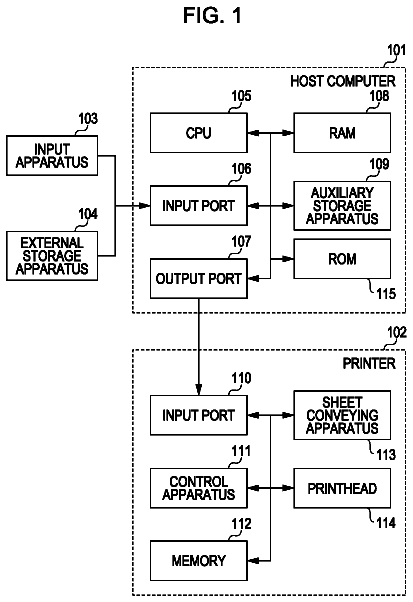
First of all, the configuration of a microscope 1 according to a first embodiment is explained by referring to FIG. 1. FIG. 1 is an explanatory diagram showing the configuration of the microscope 1 according to the first embodiment.
Overall Configuration
As typically shown in FIG. 1, the microscope 1 according to the first embodiment employs a thumbnail-image creation section 10 and an enlarged-image creation section 20. The thumbnail-image creation section 10 takes an image of an entire prepared slide PRT on which a biological sample SPL is placed. In the following description, an image of the entire prepared slide PRT is referred to as a thumbnail image. The enlarged-image creation section 20 takes an image of a biological sample SPL by enlarging the image by a magnifying power determined in advance. In the following description, the image enlarged by the magnifying power is referred to simply as an enlarged image. In addition, the enlarged-image creation section 20 is provided with a defocus-quantity detection section 30 for detecting the defocus quantity of an illumination field diaphragm existing in the enlarged-image creation section 20.
The prepared slide PRT is a biological sample SPL fixed on a slide glass by adoption of a fixing technique determined in advance. The biological sample SPL can be a tissue segment or a smear cell. The tissue can be a junction tissue of blood or the like, an epithelia tissue or both the junction tissue and the epithelia tissue. If necessary, any one of various kinds of staining is applied to the tissue segment or the smear cell. The various kinds of staining include the ordinary staining and the fluorescent staining. Representative examples of the ordinary staining are the HE (Hematoxylin-Eosin) staining, the Giemsa staining and the Papanicolaou staining. Typical examples of the fluorescent staining are the FISH (Fluorescence In-Situ Hybridization) method and the oxygen antibody method.
In addition, a label is pasted on the prepared slide PRT. The label shows peculiar information used to identify the biological sample SPL of the prepared slide PRT. The peculiar information includes the name of a person preparing the sample, a sample taking time and a sample taking date as well as the type of staining.
The microscope 1 according to this embodiment is also provided with a stage 40 on which a prepared slide PRT like the one described above is mounted. In addition, the microscope 1 is also provided with a stage driving mechanism 41 for moving the stage 40 in a variety of directions. To be more specific, the stage driving mechanism 41 is capable of moving the stage 40 in directions parallel to the surface of the stage 40 and a direction perpendicular to the surface with a high degree of freedom. The directions parallel to the surface of the stage 40 are referred to as X-axis and Y-axis directions whereas the direction perpendicular to the surface is referred to as a Z-axis direction.
In addition, the enlarged-image creation section 20 is provided with a condenser-lens driving mechanism 42 which is a typical illumination-field-diaphragm focus adjustment section.
Thumbnail-Image Taking Section
As shown in FIG. 1, the thumbnail-image creation section 10 is provided with main components such as an optical source 11, an object lens 12 and an image taking device 13.
The optical source 11 is provided on a side opposite to the prepared slide PRT with respect to the stage 40. The optical source 11 is capable of radiating bright-field illumination light or dark-field illumination light and switching from one light to the other. The bright-field illumination light is light for illuminating the biological sample SPL already subjected to the ordinary staining. The bright-field illumination light is also referred to simply as field illumination light. On the other hand, the dark-field illumination light is light for illuminating the biological sample SPL already subjected to special staining. In addition, the optical source 11 can also be an optical source capable of radiating either bright-field illumination light or dark-field illumination light. In this case, two optical sources 11 are provided. One of the two optical sources 11 is capable of radiating bright-field illumination light whereas the other optical source 11 is capable of radiating dark-field illumination light.
On top of that, the thumbnail-image creation section 10 may also have a label optical source provided separately. The label optical source not shown in FIG. 1 radiates light used for taking an image of peculiar information written on the label pasted on the prepared slide PRT.
The object lens 12 having a magnifying power determined in advance takes a line, which is normal to the prepared-slide placing surface of the stage 40 and passes through the center of the thumbnail-image creation section 10, as an optical axis SRA. The object lens 12 is provided on the same side as the prepared slide PRT with respect to the stage 40. Transmitted light passing through the prepared slide PRT put on the prepared-slide placing surface of the stage 40 is converged by the object lens 12, creating an image on the image taking device 13 provided in the rear of the object lens 12. The statement saying "the image taking device 13 provided in the rear of the object lens 12'' means that the image taking device 13 is provided at a location separated away from the object lens 12 in the direction in which the light propagates.
The light in an image taking range covering the entire prepared slide PRT put on the prepared-slide placing surface of the stage 40 creates an image on the image taking device 13. In other words, the transmitted light passing through the prepared slide PRT creates an image on the image taking device 13. The image created on the image taking device 13 is a thumbnail image which is a microscope image obtained as a result of an operation to take an image of the entire prepared slide PRT.
Enlarged-Image Taking Section
As shown in FIG. 1, the enlarged-image creation section 20 is provided with main components including an optical source 21, a condenser lens 22, an object lens 23 and an image taking device 24. In addition, the enlarged-image creation section 20 is also provided with an illumination field diaphragm not shown in the figure.
The optical source 21 radiates bright-field illumination light. The optical source 21 is provided on a side opposite to the prepared slide PRT with respect to the stage 40. In addition, another optical source for generating dark-field illumination light is provided also on the side opposite to the prepared slide PRT with respect to the stage 40 but at a location different from the optical source 21. The other optical source is not shown in FIG. 1.
The condenser lens 22 is a lens for converging bright-field illumination light radiated by the optical source 21 as well as dark-field illumination light radiated by the other optical source for generating the dark-field illumination light and guiding the converged bright-field illumination light as well as the converged dark-field illumination light to the prepared slide PRT placed on the stage 40. The condenser lens 22 takes a line, which is normal to the prepared-slide placing surface of the stage 40 and passes through the center of the enlarged-image creation section 20, as an optical axis ERA. The condenser lens 22 is provided between the optical source 21 and the stage 40. The condenser-lens driving mechanism 42 is capable of driving the condenser lens 22 to move in the direction of the optical axis ERA. That is to say, the condenser-lens driving mechanism 42 is capable of changing the position of the condenser lens 22 on the optical axis ERA.
The object lens 23 having a magnifying power determined in advance takes a line, which is normal to the prepared-slide placing surface of the stage 40 and passes through the center of the enlarged-image creation section 20, as the optical axis ERA. The object lens 23 is provided on the same side as the prepared slide PRT with respect to the stage 40. By properly replacing the object lens 23 used in the enlarged-image creation section 20, the image of the biological sample SPL can be enlarged at a variety of magnifying powers and taken. Transmitted light passing through the prepared slide PRT put on the prepared-slide placing surface of the stage 40 is converged by the object lens 23, creating an image on the image taking device 24 provided in the rear of the object lens 23. The statement saying "the image taking device 24 provided in the rear of the object lens 23'' means that the image taking device 24 is provided at a location separated away from the object lens 23 in the direction in which the light propagates.
It is to be noted that, on the optical axis ERA between the object lens 23 and the image taking device 24, a beam splitter 31 is provided. Part of transmitted light passing through the object lens 23 is guided by the beam splitter 31 to the inside of the defocus-quantity detection section 30 including the beam splitter 31 as described later.
In accordance with the pixel size of the image taking device 24 and the magnifying power of the object lens 23, an image in an image taking range on the prepared-slide placing surface of the stage 40 is created on the image taking device 24. The image taking range has a width determined in advance and a height also determined in advance. It is to be noted that, since the object lens 23 enlarges a portion of the biological sample SPL, the image taking range is sufficiently small in comparison with the image taking range on the image taking device 13.
In the configuration shown in FIG. 1, the normal line passing through the center position of the thumbnail-image creation section 10 to serve as the optical axis SRA is separated away in the Y-axis direction from the normal line passing through the center position of the enlarged-image creation section 20 to serve as the optical axis ERA by a distance D. The distance D is set at such a value which is large enough that a lens barrel (not shown) for holding the object lens 23 of the enlarged-image creation section 20 is not projected on the image taking range of the image taking device 13. However, the distance D is small enough so that the size of the microscope 1 can be reduced.
Defocus-Quantity Detection Section
As shown in FIG. 1, the defocus-quantity detection section 30 employs main components including the beam splitter 31, a condenser lens 32, two eye lenses 33 and an image taking device 34.
As explained earlier, the beam splitter 31 is provided on the optical axis ERA between the object lens 23 and image taking device 24 which are employed in the enlarged-image creation section 20 and part of transmitted light passing through the object lens 23 is guided by the beam splitter 31 to the inside of the defocus-quantity detection section 30 including the beam splitter 31. In other words, the beam splitter 31 splits the transmitted light passing through the object lens 23 into transmitted light propagating to the image taking device 24 and reflected light propagating to the condenser lens 32 employed in the defocus-quantity detection section 30 to be described later.
That is to say, the condenser lens 32 is provided at a location separated away from the beam splitter 31 in the direction of the propagation of the reflected light obtained as the splitting carried out by the beam splitter 31. The condenser lens 32 converges the reflected light obtained as the splitting carried out by the beam splitter 31 into a light beam and directs the light beam to the two eye lenses 33 provided at locations separated away from the beam splitter 31 in the toward-rear direction which is defined as the direction of the propagation of the reflected light.
The two eye lenses 33 divide the light beam coming from the condenser lens 32 into two light beams. The two light beams create a set of observation-object images on the image creation surface of the image taking device 34 provided at a location separated away from the two eye lenses 33 in the toward-rear direction which is defined as the direction of the propagation of the reflected light.
That is to say, the light passing through each of the two eye lenses 33 creates an image on the image creation surface of the image taking device 34. As a result, a pair of observation-object images are created on the image creation surface of the image taking device 34. Since light beams passing through the condenser lens 32 in a variety of directions hit the two eye lenses 33, there is a difference in phase between the observation-object images created on the image creation surface of the image taking device 34. In the following description, the pair of observation-object images are referred to as phase-difference images. The defocus-quantity detection section 30 according to this embodiment detects the defocus quantity of the illumination field diaphragm existing in the enlarged-image creation section 20 by making use of this difference in phase.
The above description explains a configuration in which the beam splitter 31 is placed between the object lens 23 and the image taking device 24. However, a light-beam splitting portion for splitting a light beam does not have to be the beam splitter 31. For example, a movable mirror can also be used as the light-beam splitting portion.
In addition, the image taking device employed in each of the thumbnail-image creation section 10, the enlarged-image creation section 20 and the defocus-quantity detection section 30 can be a one-dimensional image taking device or a two-dimensional image taking device.
It is to be noted that the enlarged-image creation section 20 and the defocus-quantity detection section 30 are explained again in detail as follows.
Control Sections
As shown in FIG. 1, the microscope 1 according to this embodiment employs a variety of control sections for controlling a variety of members included in the microscope 1. To put it concretely, the microscope 1 according to this embodiment employs an illumination control section 51 for controlling a variety of optical sources included in the microscope 1. The optical sources include the optical source 11 and the optical source 21. The microscope 1 also employs a stage-driving control section 52 for controlling the stage driving mechanism 41 and a condenser-lens-driving control section 53 for controlling the position of the condenser lens 22. The microscope 1 also employs a phase-difference-image-taking control section 54 for controlling the image taking device 34 used for taking the phase-difference images and a thumbnail-image-taking control section 55 for controlling the image taking device 13 used for taking the thumbnail image. The microscope 1 also employs an enlarged-image-taking control section 56 for controlling the image taking device 24 used for taking an enlarged image of the biological sample SPL. The illumination control section 51, the stage-driving control section 52, the condenser-lens-driving control section 53, the phase-difference-image-taking control section 54, the thumbnail-image-taking control section 55 and the enlarged-image-taking control section 56 are connected to the optical source 11/the optical source 21, the stage driving mechanism 41, the condenser-lens driving mechanism 42, the image taking device 34, the image taking device 13 and the image taking device 24 respectively by a variety of data communication lines.
In addition, the microscope 1 according to this embodiment employs an overall control section 50 provided separately for controlling the microscope 1 as a whole. The overall control section 50 is connected to the illumination control section 51, the stage-driving control section 52, the condenser-lens-driving control section 53, the phase-difference-image-taking control section 54, the thumbnail-image-taking control section 55 and the enlarged-image-taking control section 56 by a variety of data communication lines.
Each of the overall control section 50, the illumination control section 51, the stage-driving control section 52, the condenser-lens-driving control section 53, the phase-difference-image-taking control section 54, the thumbnail-image-taking control section 55 and the enlarged-image-taking control section 56 employs a CPU (Central Processing Unit), a ROM (Read Only Memory), a RAM (Random Access Memory), a storage unit, a communication unit and a processing circuit.
The above mentioned sections and their functions are explained as follows.
Illumination Control Section
The illumination control section 51 is a processing section for controlling a variety of optical sources employed in the microscope 1 according to this embodiment. When the illumination control section 51 receives information indicating a method for illuminating the biological sample SPL from the overall control section 50, on the basis of the information indicating the method, the illumination control section 51 controls the illumination of an optical source indicated by the information.
For example, the following description is focused on execution of control of the optical source 11 employed in the thumbnail-image creation section 10. In this case, the illumination control section 51 refers to the information indicating a method for illuminating the biological sample SPL in order to determine whether a bright field mode or a dark field mode is to be implemented. The bright field mode is a mode for acquiring a bright field image whereas the dark field mode is a mode for acquiring a dark field image. Then, the illumination control section 51 sets parameters according to the mode to be implemented for the optical source 11 so that the optical source 11 radiates illumination light according to the mode. Thus, the illumination light radiated by the optical source 11 propagates through an aperture on the stage 40 and arrives at the entire biological sample SPL. It is to be noted that the parameters set by the illumination control section 51 typically include the intensity of the illumination light and a parameter indicating the type of the optical source.
Next, the following description is focused on execution of control of the optical source 21 employed in the enlarged-image creation section 20. In this case, the illumination control section 51 refers to the information indicating a method for illuminating the biological sample SPL in order to determine whether a bright field mode or a dark field mode is to be carried out. Then, the illumination control section 51 sets parameters according to the mode to be implemented for the optical source 21 so that the optical source 21 radiates illumination light according to the mode. Thus, the illumination light radiated by the optical source 21 propagates through the aperture on the stage 40 and arrives at the entire biological sample SPL. It is to be noted that the parameters set by the illumination control section 51 typically include the intensity of the illumination light and a parameter indicating the type of the optical source.
The reader is advised to keep in mind that it is desirable to radiate visible light in the bright field mode as illumination light. On top of that, it is also desirable to take a marker generating light having wavelengths including an excitable wavelength as a fluorescent marker used in the special staining. In addition, in the dark field mode, the background position for the fluorescent marker is cut out.
Stage-Driving Control Section
The stage-driving control section 52 is a processing section for controlling the stage driving mechanism 41 for driving the stage 40 provided in the microscope 1 according to this embodiment. When the stage-driving control section 52 receives information indicating a method for taking an image of the biological sample SPL from the overall control section 50, on the basis of the received information indicating the method, the stage-driving control section 52 controls the stage driving mechanism 41.
For example, the following description is focused on an operation to take a thumbnail image. In this case, when the stage-driving control section 52 receives information serving as a command to take a thumbnail image of the biological sample SPL from the overall control section 50, on the basis of the received information serving as a command, the stage-driving control section 52 controls the stage driving mechanism 41 to move the stage 40 in the stage surface directions (also referred to as the X-Y axis directions) so that the entire prepared slide PRT is put in an image taking range of the image taking device 13. In addition, the stage-driving control section 52 also controls the stage driving mechanism 41 to move the stage 40 in the Z-axis direction so that the entire prepared slide PRT coincides with the focus of the object lens 12.
Next, the following description is focused on an operation carried out by the microscope 1 according to this embodiment to take an enlarged image of the biological sample SPL. In this case, when the stage-driving control section 52 receives information serving as a command to take an enlarged image of the biological sample SPL from the overall control section 50, on the basis of the received information serving as a command, the stage-driving control section 52 controls and drives the stage driving mechanism 41 to move the stage 40 in the stage surface directions (also referred to as the X-Y axis directions) so that the biological sample SPL is moved from a position between the optical source 11 and the object lens 12 to a position between the condenser lens 22 and the object lens 23.
In addition, the stage-driving control section 52 also controls and drives the stage driving mechanism 41 to move the stage 40 in the stage surface directions (also referred to as the X-Y axis directions) so that a predetermined member of the biological sample SPL is put in the image taking range of the image taking device 24.
On top of that, the stage-driving control section 52 also controls and drives the stage driving mechanism 41 to move the stage 40 in a direction perpendicular to the stage surface directions so that the predetermined member of the biological sample SPL coincides with the focus of the object lens 23. As described above, the predetermined member of the biological sample SPL has been put in the image taking range of the image taking device 24. By the way, the direction perpendicular to the stage surface directions is also referred to as the Z-axis direction or the depth direction of the tissue segment.
Condenser-Lens-Driving Control Section
The condenser-lens-driving control section 53 is a processing section for controlling the condenser-lens driving mechanism 42 for driving the condenser lens 22 employed in the enlarged-image creation section 20 in the microscope 1 according to this embodiment. When the condenser-lens-driving control section 53 receives information on a defocus quantity of the illumination field diaphragm employed in the enlarged-image creation section 20 from the overall control section 50, on the basis of the received information on a defocus quantity, the condenser-lens-driving control section 53 controls the condenser-lens driving mechanism 42.
As will be described later, if the illumination field diaphragm employed in the enlarged-image creation section 20 does not properly coincide with the focus of the condenser lens 22, the contrast of the enlarged image created on the image taking device 24 undesirably deteriorates. In order to prevent the contrast of the enlarged image from deteriorating, the overall control section 50 employed in the microscope 1 according to this embodiment carries out special processing on the defocus quantity of the illumination field diaphragm on the basis of the phase-difference images generated by the defocus-quantity detection section 30. The overall control section 50 itself will be described later in detail. The overall control section 50 outputs information representing the specially processed defocus quantity of the illumination field diaphragm to the condenser-lens-driving control section 53 in order to control the condenser-lens-driving control section 53 to change the position of the condenser lens 22 so that the focus of the condenser lens 22 is put in a state of coinciding with the illumination field diaphragm employed in the enlarged-image creation section 20.
To put it in detail, in accordance with the control executed by the overall control section 50, the condenser-lens-driving control section 53 drives the condenser-lens driving mechanism 42 to correct the position of the condenser lens 22 on the optical axis ERA so that the focus of the condenser lens 22 coincides with the illumination field diaphragm employed in the enlarged-image creation section 20.
Phase-Difference-Image-Taking Control Section
The description continues in the full USPTO document.
 Lapsed, fee not paid16 drawings