 Lapsed, fee not paid3 drawings
Lapsed, fee not paid
Wide-array inkjet printhead assembly
US 8,573,739 B2 · Assignee: Hewlett-Packard Development Company, L.P. · Inventors: Choy; Silam J. et al.
Overview
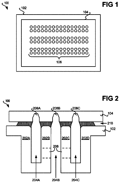
Sheet 1 of 6 from the published document. All sheets in the USPTO PDF
Abstract From the patent
A wide-array inkjet printhead assembly with die carriers includes a backbone which delivers fluid through a manifold with a number of openings. The openings are spaced apart according to a opening pitch. A plurality of inkjet die includes trenches with a trench pitch which is smaller than the opening pitch. A plurality of die carriers include a plurality of oblique tapered channels, with one end of the oblique tapered channels having pitch matching the opening pitch and interfacing with the backbone and the opposite end of the oblique tapered channels having a pitch matching the trench pitch and interfacing with the inkjet die. A method for assembling a wide-array inkjet printhead assembly is also described.
Why it's free to use
- The USPTO Official Gazette of December 30, 2025 lists it as expired on November 5, 2025 for an unpaid maintenance fee.
- It isn't on any reinstatement notice published since.
- Its 1 US relative has also lapsed, expired or never issued.
- We check US rights only. Check foreign counterparts before selling abroad.
FiledAugust 19, 2010
GrantedNovember 5, 2013
Expired (fee)November 5, 2025
Application number13/703150
Classification (CPC)B41J2/155 +6 more
Length15 claims · 12 pages
Background From the patent
Wide-array inkjet printhead assemblies typically deposit ink across the width of a substrate as it is fed through the printer. Because the wide-array printheads are substantially as wide as the substrate, there is no need for translation of the printhead. However, the increased size of the wide-array inkjet printhead assembly can also increase the number of components, increase the cost of the printhead, and lead to more stringent manufacturing tolerances.
Drawings 6
1 of 6 drawing sheets so far from the published document, cropped to the drawing. Every sheet is in the USPTO PDF.
Figures as described
- FIG. 1 is a perspective view of an illustrative wide-array inkjet printhead assembly, according to one embodiment of principles described herein
- FIG. 2 is a partially cutaway view of an illustrative wide-array inkjet printhead assembly, according to one embodiment of principles described herein
- FIG. 3A is an exploded view of an illustrative die assembly which includes a die carrier, according to one embodiment of principles described herein
- FIG. 3B is a perspective view of an illustrative die assembly which includes a die carrier, according to one embodiment of principles described herein
- FIG. 4 is a cross sectional view of an illustrative wide-array inkjet printhead assembly, according to one embodiment of principles described herein
- FIGS. 5A and 5B are cross sectional views of bubbles in illustrative slots which feed inkjet die, according to one embodiment of principles described herein
- FIG. 6 is a flowchart of an illustrative method for assembling a wide-array inkjet printhead assembly, according to one embodiment of principles described herein
Claims 15 total, 3 independent
What the patent claimed, word for word. All of it is now free to use.
- 1Independent claimA wide-array inkjet printhead assembly comprising: a backbone including a manifold for delivery of fluid through a number of openings, the openings having a opening pitch; a plurality of inkjet die, the inkjet die comprising trenches with a trench pitch which is smaller than the opening pitch; and a plurality of die carriers, the die carriers comprising a plurality of oblique tapered channels, one end of the oblique tapered channels having a pitch matching the opening pitch and interfacing with the backbone and the opposite end of the oblique tapered channels having a pitch matching the trench pitch and interfacing with the inkjet die.
- 2The assembly of claim 1, in which the die carriers have a substantially vertical channel on a first side and an angled channel on an opposite side.
- 3The assembly of claim 1, in which the die carriers are staggered back-to-back across the length of the inkjet printhead, with a portion of the die carriers being oriented to the left and a portion of the die carriers being oriented to the right.
- 4The assembly of claim 3, in which inkjet die all are placed on the die carriers in the wide-array inkjet printhead assembly with the same orientation.
- 5The assembly of claim 1, in which the inkjet die are connected to die carriers to form a die assembly and the die assembly is connected to the backbone.
- 6The assembly of claim 1, in which the oblique tapered channels extend a distance that the ink flows to the inkjet die.
- 7The assembly of claim 1, in which the die carriers further comprise a plurality of support features for supporting a shroud.
- 8The assembly of claim 7, in which the support features comprise a first post on a first side of the die carrier and a second post on a second side of the die carrier.
- 9The assembly of claim 7, in which a die connection comprises a bend in conductors that extend from a flex cable to contacts on the inkjet die such that the flex cable is disposed below the plurality of support features on the die carriers.
- 10The assembly of claim 1, in which both the die carriers and the backbone are formed from injection molded thermoplastic.
- 11The assembly of claim 1, in which the opening pitch is greater than 2 millimeters and the trench pitch is less than 1.5 millimeters.
- 12Independent claimA die carrier comprising: a first planar surface; a second planar surface; a plurality of oblique tapered channels extending through the die carrier from the first planar surface to the second planar surface, the oblique tapered channels having a first pitch at the first planar surface and a second smaller pitch at the second planar surface, the first planar surface interfacing with manifold openings in a backbone of a printhead assembly and the second planar surface interfacing with trenches in an inkjet die.
- 13The die carrier of claim 12, further comprising a plurality of support features for supporting a shroud, the plurality of support features comprising a first post on a first side of the die carrier and a second post on a second side of the die carrier.
- 14The die carrier of claim 12, in which the first pitch is greater than 2 millimeters and matches a opening pitch of fluidic channels in an underlying backbone and the second smaller pitch is less than 1.5 millimeters and matches a trench pitch of the inkjet die.
- 15Independent claimA method for assembling a wide-array inkjet printhead assembly comprises: attaching a inkjet die to a die carrier such that trenches on the inkjet die are in fluidic communication with oblique tapered channels which extend through the die carrier; attaching a flex cable to the die carrier to form a die assembly; attaching a plurality of the die assemblies to a backbone in back-to-back staggered configuration, such that the die assemblies extend across a substantial portion of the backbone and flex cables for each die assembly extend to one side of the printhead; in which the oblique tapered channels in the plurality of die assemblies are in fluidic communication with manifold openings in the backbone.
Description
Background
Wide-array inkjet printhead assemblies typically deposit ink across the width of a substrate as it is fed through the printer. Because the wide-array printheads are substantially as wide as the substrate, there is no need for translation of the printhead. However, the increased size of the wide-array inkjet printhead assembly can also increase the number of components, increase the cost of the printhead, and lead to more stringent manufacturing tolerances.
Brief description of the drawings
The accompanying drawings illustrate various embodiments of the principles described herein and are a part of the specification. The illustrated embodiments are merely examples and do not limit the scope of the claims.
FIG. 1 is a perspective view of an illustrative wide-array inkjet printhead assembly, according to one embodiment of principles described herein.
FIG. 2 is a partially cutaway view of an illustrative wide-array inkjet printhead assembly, according to one embodiment of principles described herein.
FIG. 3A is an exploded view of an illustrative die assembly which includes a die carrier, according to one embodiment of principles described herein.
FIG. 3B is a perspective view of an illustrative die assembly which includes a die carrier, according to one embodiment of principles described herein.
FIG. 4 is a cross sectional view of an illustrative wide-array inkjet printhead assembly, according to one embodiment of principles described herein.
FIGS. 5A and 5B are cross sectional views of bubbles in illustrative slots which feed inkjet die, according to one embodiment of principles described herein.
FIG. 6 is a flowchart of an illustrative method for assembling a wide-array inkjet printhead assembly, according to one embodiment of principles described herein.
Throughout the drawings, identical reference numbers designate similar, but not necessarily identical, elements.
Detailed description
Wide-array inkjet printhead assemblies typically deposit printing fluid across the width of a substrate as it is fed through the printer. Because the wide-array printheads are substantially as wide as the substrate, there is no need for translation of the printhead. However, the increased size of the wide-array inkjet printhead assembly can also increase the number of components, increase the cost of the printhead, and lead to more stringent manufacturing tolerances.
According to one illustrative embodiment, a wide-array inkjet printhead assembly is composed of an array of printhead die. These printhead die are among highest precision components in the printhead assembly and contain the ink droplet ejection mechanisms. For example, the printhead die may contain thermal, piezo, or MEMs ejection elements. These ejection elements are activated to force droplets of fluid out of an array of nozzles. These droplets may have a volume on the order of 1-30 picoliters. The droplets may take the form of ink droplets are deposited on a substrate to create the desired image.
The remainder of the printhead assembly supports this droplet ejection functionality of the printhead die. For example, a printhead assembly structurally supports the printhead die, provides electrical connections to each printhead die, and routes ink to each nozzle in each printhead die.
In one embodiment, each printhead die is packaged with an individual die carrier before mounting the resulting modules to the manifold assembly. The die carriers act as physical and fluidic interface between the manifold assembly and the inkjet die. The use of die carriers allows for modularity in constructing the printhead and allows the manifold to be formed with larger, less precise features. Consequently, the manifold can be formed using low cost materials and methods of fabrication. This can result in a significant reduction in the cost to produce the manifold, while maintaining or improving the printing performance of the printhead.
In the following description, for purposes of explanation, numerous specific details are set forth in order to provide a thorough understanding of the present systems and methods. It will be apparent, however, to one skilled in the art that the present apparatus, systems and methods may be practiced without these specific details. Reference in the specification to "an embodiment," "an example" or similar language means that a particular feature, structure, or characteristic described in connection with the embodiment or example is included in at least that one embodiment, but not necessarily in other embodiments. The various instances of the phrase "in one embodiment" or similar phrases in various places in the specification are not necessarily all referring to the same embodiment.
FIG. 1 is a perspective view of an illustrative wide-array inkjet printhead assembly (100). The printhead
includes a backbone (115), a plurality of inkjet die (105), a shroud (110), a circuit board
and flex cables
which electrically connect to the die
to the circuit board (125). The backbone
structurally supports the printhead die
and routes ink or any other suitable fluid to each of the printhead die (105). A manifold structure within the backbone
accepts ink from an ink reservoir and distributes the ink to the individual die (105). The shroud
attaches to the backbone
and encloses the die assemblies to provide a sealing surface for a cap which is placed over the die
when they are not in use. The shroud
and cap prevent the die
from drying out and subsequently malfunctioning. The shroud
may be formed from a number of materials using a variety processes. According to one illustrative embodiment, the shroud
is formed from stainless steel using sheet metal techniques.
The circuit board
electrically controls the individual firing mechanisms within the die
so that the appropriate color, amount, and pattern of ink is ejected from the die
to create the desired image on a substrate. The circuit board
is connected to the die
by flex cables (120). Flex cables
contain a number of parallel conductors which are sandwiched between two flexible sheets. Typically, the flexible sheets are a plastic such as polyimide, polyester or PEEK films. The shroud (110), flex cables (120), electrical connections at the ends of the flex cables (120), circuit board (125), and sealing the perimeter of the shroud
over the electrical connections are discussed in U.S. patent application Ser. No. 13/703,171 entitled "Wide-Array Inkjet Printhead Assembly with a Shroud," attorney docket number 201000617, to Silam J. Choy, filed Aug. 19, 2010, which is hereby incorporated by reference in its entirety.
The inkjet die
are among the highest precision parts in the printhead assembly
and represent a significant portion of the cost of the printhead (100). In a thermal inkjet system, the die
are typically manufactured from silicon using lithographic or other techniques to produce firing chambers which are arranged in a trench along the length of the die (105). The firing chambers include a cavity, a resistive heater adjacent to the cavity, and a nozzle. The ink or any other suitable fluid is fed into the trench and enters the cavities of the firing chambers. To eject an ink droplet, an electrical current is passed through the flex cable
to the resistive heater. The heater rapidly heats to a temperature above the boiling point of the ink. This creates a localized vapor bubble in the ink filled cavity and sharply increases the pressure within the cavity. This ejects an ink droplet from the nozzle. After the current is removed, the heater rapidly cools and the vapor bubble collapses, thereby drawing more liquid into the cavity from the trench. For purposes of illustration, the geometry of the die
has been simplified in the figures. The die
are illustrated as having four parallel trenches which run along a substantial length of the die (105), with each trench being dedicated to a specific ink color. For example, each die
may dispense magenta, cyan, yellow and black ink. The die are arranged in a staggered configuration so that trenches from the die
are able to dispense ink of each color across substantially the entire width of a substrate which passes under the printhead (100).
To ensure high print quality, the array of inkjet die
should be tightly aligned in all six degrees of motion. For example, all the printheads
may be coplanar to within 100 to 200 microns to ensure that the nozzle to media distance is substantially similar. This improves drop placement as the media is continuously advanced under the printhead. The larger the variation in nozzle to media distance, the larger the dot placement error.
In most embodiments, the printhead
would be a least as long as the media size. For example for A4 media, the staggered die
array would be at least 210 millimeters long and possibly longer. Additionally, for print quality, the printhead
should deliver ink to the die
with a relatively uniform pressure. This helps to ensure that the ink droplets delivered by the inkjet die
are uniform.
FIG. 2 is a partially cutaway view of an illustrative wide-array inkjet printhead assembly (100). In this view the shroud
has been partially cutaway to show the underlying die carriers (107, 109) and other aspects of the printhead (100). In one embodiment, both the left and right die carriers (107, 109) are identical, but oriented in different directions. Because the die carriers (107, 109) are identical, only a single die carrier design needs to be manufactured. The higher volume production results in lower costs per part.
As discussed above, a flex cable
connects each die carrier (107, 109) to the circuit board (125). The first end of the flex cable
makes a first connection with the circuit board (125), which is labeled in FIG. 2 as the board connection (122). The other end of the flex cable
makes a second connection with the contact pads on the die
which is labeled in FIG. 2 as the die connection (124). These connections (122, 124) may be made in a variety of ways. One design aspect of the die connection
is that the die connection
and the flex cable
as it leaves the die connection
should not interfere with the fit of the shroud (110).
The shroud
includes a perimeter flange
which is sealed to the backbone (115). The shroud
serves at least three functions. First, the shroud
protects the underlying components from damage and contamination. Second, the shroud
provides a planar surface
which is at approximately the same level as the top of the die (105). This planar surface
supports a wiper which passes over and cleans the die (105). Third, the shroud
provides a uniform sealing surface for a cap which covers the die
when the printer is not in use. Covering the die
with the cap can prevent the evaporation of solvent from the ink. When the solvent evaporates, the ink solids are left behind. These ink solids can accumulate and cause a number of issues including blocked nozzles and misdirected ink droplets. The cap seals onto the shroud
to enclose the die
in a sealed cavity. As ink begins to evaporate from the die (105), the humidity in the sealed cavity increases and prevents further evaporation.
The dashed line labeled 4-4 indicates the location and viewing direction of FIG. 4. As discussed below, FIG. 4 shows the interior of manifold openings in the backbone
and ink channels in the die carriers (107, 109).
FIG. 3A is an exploded view of an illustrative die assembly
which includes a die carrier (108), die (105), and flex cable (120). As discussed above, the lower surface of the die carrier
is sealed over manifold openings in the backbone (115, FIG. 2). Oblique tapered channels
in the die carrier
direct fluid from the lower surface
to the upper surface
of the die carrier (108). At the upper surface
of the die carrier
the oblique tapered channels
have approximately the same pitch and length as the trenches
in the die (105). Thus the oblique tapered channels
direct ink from the manifold openings in the backbone (115, FIG. 2) through the die carrier
and into the trenches (145).
Because the die carrier
is similar in length to the die (105), the die carrier
can be molded flat enough to allow the die
to be bonded to the die carrier
without requiring costly secondary operations. For example, if a 25 millimeter long die requires an upper surface flatness of 0.1 millimeter, the flatness specification is 0.4% of the die carrier length. This is within the capability of precision thermoplastic injection molding without any secondary operations.
The flex cable
is attached to the die contacts (106). According to one embodiment, the electrical conductors in the flex cable
are copper ribbons or wires, which are covered with gold. These copper ribbons extend beyond the sandwiching polymer films. In one example, the copper ribbons are attached to the gold plated die contacts
using Tape Automated Bonding (TAB). After making the electrical connections, a number of additional operations can be performed to ensure that the connection is electrically/mechanically secure and that the flex cable
exits the connection at the desired angle. For example, the connection may be encapsulated with a curable polymer (i.e. "glob topping"). In some embodiments, a small amount of curable polymer may be deposited under the flex cable
and adhere to the underside of the flex cable
to the die
and/or die carrier (108). An additional quantity of curable polymer is then deposited on top of the connection.
FIG. 3B is a perspective view of a die assembly (140). The die assembly
includes the die (105), the die carrier (108), the flex cable
and the die connection (124). The die assembly
is a modular unit which can be independently tested to verify its functionality. For example, the die assembly
can be electrically tested to verify that the flex cable
makes a proper electrical connection with the die
through the die connection (124). The electrical test may also include checking electrical functions of the die (105). For example, the resistance of the various heater elements in the die
can be measured by attaching appropriate testing equipment to the opposite end of the flex cable (120).
The embodiment of the die assembly
shown in FIG. 3B has a right facing die carrier (108). To form a die assembly
with a left facing die carrier (108), the die carrier
is rotated 180 degree prior to adhering the die
to the upper surface (138, FIG. 3A) of the die carrier (108). However, the die
and flex cable
orientation remains the same. This allows the flex cables
on both the right and left facing die carriers
to come off the same side and simplifies their connection to a single circuit board (125, FIG. 2).
The die carriers
include a number of features which are configured to interface with and support the shroud (110, FIG. 2). In this example, the support features include posts
on either side of the die
and corners
at either end of the die carrier (108). The upper surfaces of these support features (135, 137) are formed in a common plane. When the shroud (110, FIG. 2) is put in place, the support features (135, 137) make contact with the under surface of the shroud (110, FIG. 2). This provides additional support for the center of the shroud (110, FIG. 2).
FIG. 4 is a cross sectional view of an illustrative wide-array inkjet printhead assembly along line 4-4 shown in FIG. 2. In this embodiment, cross sections are taken of two back-to-back die carriers: a left facing die carrier
and a right facing die carrier (109). As discussed above, the backbone
provides structural support for the die carriers (107, 109) and contains manifold openings (166). The manifold openings
have a opening pitch
which is significantly greater than the trench pitch
of the die (105). According to one illustrative embodiment, the opening pitch
is greater than 2 millimeters and the trench pitch
is less than 1.5 millimeters. For example, the opening pitch
may be approximately 3 millimeters and the trench pitch
may be approximately 1 millimeter.
The size of the die
is a significant factor in the overall cost of the printhead (100). As discussed above, the die
can be formed from a silicon wafer using lithography techniques. It is conceivable that a single inkjet die
could be created which would span the width of the printhead
and substrate. For a number of reasons this approach may be more expensive and result in a printhead which is less robust than a printhead which uses an array of smaller die. For example, the single large die would be more expensive to produce than the equivalent number of smaller die, may have tighter manufacturing tolerances, and may be more likely to have a fatal manufacturing error which would result in the larger die being scrapped. Further, in operation, the larger die may be significantly more fragile due to its small cross section and greater length. Additionally, the thermal mismatch between the larger die and the supporting material may be exacerbated by the length. Consequently, there are significant cost and engineering benefits to reducing the size of the inkjet die.
In addition to manufacturing the die
with a shorter length, the width of the die
can be minimized by reducing the distance between the trenches (145). For example, the trench pitch
can be reduced to less than 1 millimeter without detriment to the operation of the firing chambers. By reducing the width of the die (105), more die
can be manufactured from a single silicon wafer, resulting in a reduced cost per die.
However, supplying ink to die with more closely spaced trenches can be challenging. Specifically, manufacturing a backbone which spans the length of printhead and also contains manifold openings which are spaced less than a millimeter apart is challenging. Plastic injection molding, which is a low cost, high volume production method, cannot reliably produce a backbone with manifold openings with less than a millimeter pitch. A variety of other more expensive approaches could be used. For example, the backbone could be machined from metal. However, machining the backbone results in manufacturing costs which are two or three orders of magnitude greater than injection molding.
The use of a die carrier (107, 109) with oblique tapered slots
resolves this challenge by allowing the manifold opening pitch
to remain relatively large, while permitting the die trench pitch
to be reduced. The backbone
can still be designed and manufactured as an inexpensive injection molded part and the die width can be reduced to lower the cost of the die (105). As discussed above, the oblique tapered channels
act as fluidic interfaces between the manifold openings
and the die trenches (145).
Additionally the oblique nature of the channels
in the die carriers (107, 109) allows the back-to-back distance
between the die
to be minimized. Each of the tapered channels
are arranged at a different angle to transition between the manifold opening pitch (e.g. 2.5 millimeter) and the die trench pitch (e.g. <1 millimeter). In the center of the staggered row, the oblique tapered channels of the die carriers (107, 109) are substantially vertical. This allows the die
to be located to one side of the die carrier such the back-to-back distance
between the die
on the left facing and right facing die carriers (107, 109) is minimized. Minimizing the back-to-back distance between the die
can significantly reduce printing errors. For example, a number of factors which directly influence printing quality, such as timing and droplet flight distances, influenced by the back-to-back distance
between the die (105). Specifically, the greater the lateral distance between the die (107, 109), the greater the variability in the substrate distance and droplet flight distances. Other factors, such as ejection timing, are also influenced by the back-to-back distance
between the die (105).
FIGS. 5A and 5B are cross sectional views of a small portion of two different die and their ink delivery system. The die are located at the bottom of the figures and the ink is delivered to the die through slot/channels from the top of the figures. In general, inkjet die can operate in any orientation, but typically the droplets are ejected downward from a die onto an underlying substrate.
FIG. 5A is a cross sectional diagram of a bubble
trapped in a straight sided manifold slot (605). Bubbles
can form in the slots
and channels which feed the inkjet die
for a variety of reasons. For example, the bubble
may have been entrained in the ink and carried by the ink into the slot. Additionally, the bubble
may have entered through the nozzle. However, one of the more common reasons that bubbles
form in ink is related to a change in temperature of the ink. Ink, like most fluids, has a temperature dependent capacity to contain dissolved gasses. Colder ink can contain more dissolved gas than warmer ink. As the ink passes through the manifold, it can become warmer by absorbing heat generated by the operation of the thermal inkjets. The warmer ink no longer has the capacity to contain all of the dissolved gas. Consequently, the gas comes out of the ink as bubbles (610). These bubbles
can grow over time and eventually obstruct the slot (605), which causes pressure differences at the firing chambers and results in image degradation. The bubbles
can also migrate into the firing chambers, potentially causing malfunction and damage. Consequently, it is desirable to prevent the bubbles
from lodging near the die
and to provide a mechanism to manage the bubbles
which do occur.
In the embodiment shown in FIG. 5A, the bubble
is lodged in the slot
and contacts both walls of the slot. As the width of the slot
decreases, bubbles
are more likely to fill the slot
and stick to the side walls. The radius "R" of the bubble
is determined by the pressure differential across the bubble wall. The bubble
tends to grow in the direction which will allow the largest bubble radius. This is also the direction of least resistance for the bubble
to travel. Because the bubble
is trapped in a slot
with parallel sides, the bubble
will tend to grow in the direction of the die
and farther into the backbone
as shown by the arrows. This is undesirable because the bubble
remains trapped in the slot
and has a tendency to grow in both upward and downward. Additionally during printing, fluid would travel down to the die, potentially pushing the bubble towards the die. As discussed above, when the bubble
grows it will have a tendency to obstruct ink flow and interfere with the function of the firing chambers in the die (614).
FIG. 5B is a cross sectional diagram of a die carrier
which includes an oblique tapered channel (155). A bubble
is inside the oblique tapered channel (155). Unlike the slot (605, FIG. 5A), the tapered channel
has nonparallel walls. The bubble
has a tendency to grow in the direction of least resistance, which is toward the larger end of the tapered channel
and away from the die (105). As the bubble grows, it can escape by progressively moving up the tapered channel
and into a plenum or other passageway in the backbone. Once the bubble
is away from the die
and exits the die carrier
it can be extracted from the ink stream.
FIG. 6 is a flowchart of an illustrative method for assembling a wide-array inkjet printhead assembly. The method includes attaching the die to a die carrier
such that trenches on the die are in fluidic communication with oblique tapered slots which extend through the die carrier. The flex cable is attached to the die to form a die assembly (810). The die assembly can be either right handed or left handed depending on the orientation of the die carrier. The die assembly is a modular component which can be separately tested to verify its function (815). For example, the die assembly may be electrically and/or fluidically tested prior to incorporation of the die assembly into a wide-array printhead.
A plurality of die assemblies is attached to a backbone in back-to-back staggered configuration (820). The die assemblies extend across a substantial portion of the length of the backbone and flex cables for each die assembly extend to one side of the printhead to facilitate making electrical connections to a single circuit board using minimum length flex cables. The flex cables are attached to the circuit board
and a shroud is sealed over the die assemblies
with the upper surfaces of the die extending out of apertures in the shroud. As discussed above, the shroud provides a continuous capping surface around the printheads and protects the flex circuits from wiping operations. Support posts and other features on the die carriers support the shroud from wiping and capping forces and position the shroud height relative to the die.
The descriptions and examples given above are only illustrative. Although plastic and injection molding are described, many different material and processes could be used. For example, filled polymers, metals, ceramics and other materials could be shaped into the various components of the printhead. Possible fabrication methods include injection molding, machining, laser machining, laminating and other techniques. Additionally, steps may be added, omitted, or reordered. For example, in some embodiments, the flex cable may be attached to the die prior to attaching the die to the die carrier. Additional steps of encapsulating the flex cable connections can be added. A variety of other steps could be also be added.
In conclusion, the specification and figures describe a wide-array inkjet printhead assembly which incorporates die carriers. The die carriers support the die and provide a mechanical and fluidic interface between the manifold openings in the backbone. The die carriers contain oblique tapered slots which adapt the pitch of the manifold openings to the pitch of the trenches on the die. The die carriers also allow the distances between the die to be minimized by placing the die carriers in a staggered back-to-back configuration. The die carriers provide additional advantages, including but not limited to, compensating for irregularities in the flatness of the backbone and guiding bubbles in the ink away from the die.
The preceding description has been presented only to illustrate and describe embodiments and examples of the principles described. This description is not intended to be exhaustive or to limit these principles to any precise form disclosed. Many modifications and variations are possible in light of the above teaching.
In this description
About 4,360 words. The USPTO PDF has it with every drawing.
Timeline & family
Timeline From USPTO dates
Maintenance fees
Fees are due 3.5, 7.5 and 11.5 years after grant. This patent expired on November 5, 2025, so the fee marked "not paid" was the one that went unpaid.
3.5-year feeDue May 5, 2017Paid
7.5-year feeDue May 5, 2021Paid
11.5-year feeDue May 5, 2025Not paid
US family 2 documents, by filing date
Published applicationUS 2013/0106954 A1
WIDE-ARRAY INKJET PRINTHEAD ASSEMBLY
Filed Aug 2010 · published May 2013Published application
This documentUS 8,573,739 B2
Wide-array inkjet printhead assembly
Filed Aug 2010 · granted Nov 2013Lapsed, fee not paid
Earlier publications, parents and continuations. None of them can still be enforced, or this patent would not be listed.
US patents it cites 12
US 6,755,513US 7,175,256US 7,175,265US 7,416,277US 7,441,864US 7,669,964US 8,393,712US 2002/0140776US 2007/0210031US 2008/0170109US 2008/0174636US 2009/0141093
Prior art cited by the examiner or applicant. Useful when you check your own idea for novelty.
Sources & verification
Verification
- The USPTO Official Gazette of December 30, 2025 lists it as expired on November 5, 2025 for an unpaid maintenance fee.
- It isn't on any reinstatement notice published since.
- Its 1 US relative has also lapsed, expired or never issued.
- Rechecked against USPTO records every day.
- We check US rights only. Check foreign counterparts before selling abroad.
Confirm it yourself
- Open the file history on Patent Center.
- The status should read "Patent Expired Due to NonPayment of Maintenance Fees Under 37 CFR 1.362".
- Check the documents for any later petition to revive or reinstate.
Official USPTO records
USPTO Official GazetteNotice of Expiration of Patents Due to Failure to Pay Maintenance Fee, issue of December 30, 2025.Where this listing came fromMaintenance fee recordEnter the patent number to see its fee history.USPTO FeesFull published documentText and every drawing sheet as a PDF.USPTOFile historyStatus, office actions, notices, fee records and petitions.USPTO Patent CenterPatent Public Search recordSearchable full text and bibliographic data.USPTO
Everything on this page comes from the documents linked above.