Lapsed, fee not paid8 drawings
Medical Devices · US 8,573,220 B2
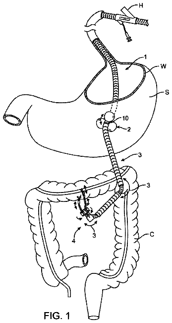
Device and method for tracheotomy
A device (11) for facilitating tracheotomy.
US 8,573,464 B2 · Assignee: Ethicon Endo-Surgery, Inc. · Inventors: Nalagatla; Anil K. et al.
Sheet 1 of 51 from the published document. All sheets in the USPTO PDF
A stapling cartridge assembly for a circular stapling instrument includes a casing, a staple driver, and a blade. The staple driver is receivable within the casing and configured to move within the casing from a pre-fired position to a fired position. The blade is attachable to the staple driver. The blade includes a cutting edge and a breakaway washer attachment member for fixedly attaching to a breakaway washer when the staple driver is moved from the pre-fired position to the fired position.
Circular stapling instruments are well known in the surgical art for bowel surgery. An example of such a device is the Endopath ILS ECS 25 Endoscopic Curved Intraluminal Stapler made by Ethicon Endo Surgery Inc. Many circular stapler patents exist, for example U.S. Pat. No. 4,207,898 to Becht, U.S. Pat. No. 4,351,466 to Noiles, U.S. Pat. No. 5,292,053 to Bilotti et al., and U.S. Pat. No. 5,344,059 to Green et. al. Typically circular stapling instruments are designed to be used once, during which cutting and stapling is completed, and then disposed of. The annular blade used for cutting tissue is advanced during the cutting and then retracted back into the device after use, thereby protecting the annular blade knife edge. However the circular stapling instrument may be inadvertently reused a second time if the circular stapling instrument is not immediately disposed of after the first use
1 of 51 drawing sheets so far from the published document, cropped to the drawing. Every sheet is in the USPTO PDF.
What the patent claimed, word for word. All of it is now free to use.
The present disclosure relates generally to a breakaway washer attachment member of a blade of a circular stapler.
Circular stapling instruments are well known in the surgical art for bowel surgery. An example of such a device is the Endopath ILS ECS 25 Endoscopic Curved Intraluminal Stapler made by Ethicon Endo Surgery Inc. Many circular stapler patents exist, for example U.S. Pat. No. 4,207,898 to Becht, U.S. Pat. No. 4,351,466 to Noiles, U.S. Pat. No. 5,292,053 to Bilotti et al., and U.S. Pat. No. 5,344,059 to Green et. al.
Typically circular stapling instruments are designed to be used once, during which cutting and stapling is completed, and then disposed of. The annular blade used for cutting tissue is advanced during the cutting and then retracted back into the device after use, thereby protecting the annular blade knife edge. However the circular stapling instrument may be inadvertently reused a second time if the circular stapling instrument is not immediately disposed of after the first use. On occasion reusable circular stapling instruments may leave the annular blade in an advanced position after use. This may pose a hazard to the user related to an exposed sharp edge. Some reusable circular stapling instruments rely solely on friction to retain a solid cutting board over and covering the annular blade knife edge. This is not a reliable means for covering the exposed annular blade knife edge as in some cases the cover may separate from the annular blade knife edge exposing the annular blade knife edge.
An apparatus for a circular stapling instrument, and a method for its use, is needed to reduce one or more problems of the prior circular stapling instruments.
The present disclosure is defined by the claims, and nothing in this section should be taken as a limitation on those claims.
In one aspect, a stapling cartridge assembly for a circular stapling instrument is provided. The stapling cartridge assembly comprises a casing, a staple driver, and a blade. The staple driver is receivable within the casing and configured to move within the casing from a pre-fired position to a fired position. The blade is attachable to the staple driver. The blade comprises a cutting edge and a breakaway washer attachment member for fixedly attaching to a breakaway washer when the staple driver is moved from the pre-fired position to the fired position.
In another aspect, a circular stapling instrument is provided. The circular stapling instrument comprises a casing, a staple driver, an anvil assembly, and a blade. The staple driver is disposed within the casing and moveable within the casing from a pre-fired position to a fired position. The anvil assembly comprises a breakaway washer assembly attached to an anvil base surface. The anvil assembly is moveable from an open position away from the casing to a closed position adjacent the casing. The blade is attached to the staple driver. The blade comprises a breakaway washer attachment member. When the staple driver is in the pre-fired position, the breakaway washer is not cut by the blade and the breakaway washer attachment member is not attached to the breakaway washer. When the staple driver is in the fired position and the anvil assembly is in the closed position, the blade cuts the breakaway washer and the breakaway washer attachment member fixedly attaches to the cut breakaway washer.
In an additional aspect, a method of locking a blade to a breakaway washer of a circular stapling instrument is provided. In one step, a circular stapling instrument is provided. The provided circular stapling instrument comprises a casing, a staple driver, an anvil assembly, and a blade. The staple driver is moveably disposed within the casing. The anvil assembly comprises a breakaway washer attached to an anvil base surface. The blade is attached to the staple driver. In another step, the anvil assembly is moved from an open position away from the casing to a closed position adjacent the casing. In an additional step, the staple driver is moved from a pre-fired position, in which the blade has not cut the breakaway washer and a breakaway washer attachment member of the blade has not attached to the breakaway washer, to a fired position in which the blade cuts the breakaway washer and the breakaway washer attachment member of the blade fixedly attaches to the cut breakaway washer.
The disclosure can be better understood with reference to the following drawings and description. The components in the figures are not necessarily to scale, emphasis instead being placed upon illustrating the principles of the disclosure.
FIG. 1 illustrates a perspective view of a reusable circular stapling instrument having an open assembly architecture, in accordance with one preferred embodiment;
FIG. 2 illustrates a perspective view of the reusable circular stapling instrument of FIG. 1 with the instrument in the open position with an anvil assembly separated from the remainder of the reusable circular stapling instrument;
FIG. 3 illustrates an exploded perspective view of a handle and shaft assembly of the reusable circular stapling instrument of FIG. 1;
FIG. 3A illustrates a cross-sectional view through line 3A-3A of a portion of a reciprocating anvil adjusting rod of the reusable circular stapling instrument of FIG. 3;
FIG. 3B illustrates a cross-sectional view through line 3B-3B of another portion of the reciprocating anvil adjusting rod of the reusable circular stapling instrument of FIG. 3;
FIG. 4 illustrates an exploded perspective view of a stapling reload assembly of the reusable circular stapling instrument of FIG. 1;
FIG. 5 illustrates a partial cross-sectional view through a stapling reload assembly of the reusable circular stapling instrument of FIG. 1 in an unassembled configuration;
FIG. 6 illustrates a cross-section view through a stapling reload assembly of the reusable circular stapling instrument of FIG. 1 in an assembled configuration with an anvil assembly in an open position and an annular blade in a pre-fired position;
FIG. 7 illustrates the view of FIG. 6 with the anvil assembly moved to a closed position and with the annular blade still being in the pre-fired position;
FIG. 8 illustrates an exploded perspective view of the anvil assembly of the reusable circular stapling instrument of FIG. 1;
FIG. 9 illustrates a flowchart of one embodiment of a method of aligning a stapling reload assembly of a circular stapling instrument;
FIG. 10 illustrates an exploded perspective view of another embodiment of an anvil assembly;
FIG. 11 illustrates a perspective view of the reusable circular stapling instrument of FIG. 1 replacing the anvil assembly with the anvil assembly of FIG. 10 separated from the remainder of the reusable circular stapling instrument;
FIG. 12 illustrates an exploded perspective view of an additional embodiment of an anvil assembly;
FIG. 13 illustrates a perspective view of the reusable circular stapling instrument of FIG. 1 replacing the anvil assembly with the anvil assembly of FIG. 12 separated from the remainder of the reusable circular stapling instrument;
FIG. 14 illustrate a flowchart showing one embodiment of a method of manufacturing an anvil assembly;
FIGS. 15A and 15B illustrate perspective assembly views, during different stages of assembly, of an anvil closure knob and a reciprocating anvil adjusting rod of the reusable circular stapling instrument of FIG. 1;
FIGS. 16A and 16B illustrate perspective assembly views, during different stages of assembly, of the anvil closure knob connected with the reciprocating anvil adjusting rod of FIGS. 15A and 15B along with a handle of the reusable circular stapling instrument of FIG. 1;
FIGS. 17A, 17B and 17C illustrate perspective assembly views, during different stages of assembly, of the anvil closure knob connected with the reciprocating anvil adjusting rod and the handle of FIGS. 16A and 16B along with a firing bar of the reusable circular stapling instrument of FIG. 1;
FIGS. 18A and 18B illustrate perspective assembly views, during different stages of assembly, of the anvil closure knob connected with the reciprocating anvil adjusting rod, the handle, and the firing bar of FIGS. 17A, 17B, and 17C along with a carrier cover of the reusable circular stapling instrument of FIG. 1;
FIGS. 19A, 19B and 19C illustrate perspective assembly views, during different stages of assembly, of the anvil closure knob connected with the reciprocating anvil adjusting rod, the handle, the firing bar, and the carrier cover of FIGS. 18A, and 18B along with a shaft assembly of the reusable circular stapling instrument of FIG. 1;
FIG. 20 illustrates a perspective view of a curved reusable circular stapling instrument having an open assembly architecture, in accordance with another preferred embodiment;
FIG. 21 illustrates an exploded perspective view of the curved reusable circular stapling instrument of FIG. 20;
FIG. 22 illustrates a cross-section view of a curved circular stapling instrument having a frictional reducing member, with the instrument in an open condition;
FIG. 23 illustrates a curved cross-section view of a circular stapling instrument having a frictional reducing member, with the instrument in a closed position before firing staples;
FIG. 24 illustrates a cross-section view of a curved circular stapling instrument having a frictional reducing member, with the instrument in a fully fired condition upon firing staples;
FIG. 25 illustrates a perspective view of a firing bar of a curved circular stapling instrument having a frictional reducing member;
FIG. 26 illustrates an exploded perspective view of a firing bar of a circular stapling instrument having a frictional reducing member;
FIG. 27 illustrates a cross-section view of a firing bar of a circular stapling instrument having a frictional reducing member;
FIG. 28 illustrates an enlarged side view of a firing bar of a circular stapling instrument having an alternate embodiment of a frictional reducing member adjacent a reciprocating anvil adjusting rod;
FIG. 29 illustrates a cross-section view of an annular blade of the stapling reload assembly of the circular stapling instrument of FIG. 4;
FIG. 30 illustrates a perspective view of an annular breakaway washer attached to a protective member;
FIG. 31 illustrates the view of FIG. 7 with the annular blade moved to the fired position cutting an annular breakaway washer while the anvil assembly is in the closed position;
FIG. 32 illustrates a close-up view, within the dotted circle of the annular blade of FIG. 31, showing the annular blade cutting the annular breakaway washer;
FIG. 33 illustrates the view of FIG. 31 with the anvil assembly having been moved back into the open position after the annular blade was fired;
FIG. 33A illustrates a close-up side view of one embodiment of an anvil control member connected to a handle of a reusable circular stapling instrument;
FIG. 34 illustrates the view of FIG. 33 with an anvil of the anvil assembly removed from the circular stapling instrument and the annular breakaway washer and a protective member attached to the annular blade;
FIG. 35 illustrates the view of FIG. 34 with a new anvil having been attempted to be attached to the stapling reload assembly and the protective member and the annular breakaway washer interfering with the attachment;
FIG. 36 illustrates a close-up view within the dotted circle of FIG. 35 showing the protective member and the annular breakaway washer interfering with the attachment of the new anvil to the stapling reload assembly;
FIG. 37 illustrates a flowchart of one embodiment of a method of locking a blade to a breakaway washer of a circular stapling instrument;
FIG. 38 illustrates a cross-sectional view through the reusable circular stapling instrument of FIG. 1 with the anvil assembly disposed in an open position, out of a firing zone, away from a casing with a firing trigger in a locked, pre-fired state;
FIG. 38B illustrates a close-up view showing the relationship between a firing trigger and the firing bar in the assembled condition of FIG. 17C;
FIG. 39 illustrates a partial perspective view of the cross-sectional view of FIG. 38;
FIG. 40 illustrates a cross-sectional view through line 40-40 of FIG. 38;
FIG. 41 illustrates a cross-sectional view through the reusable circular stapling instrument of FIG. 1 with the anvil assembly disposed in a closed position, in the firing zone, adjacent the casing with the firing trigger in an unlocked, pre-fired state ready to fire;
FIG. 42 illustrates a partial perspective cross-sectional view of FIG. 41;
FIG. 43 illustrates a cross-sectional view through line 43-43 of FIG. 41;
FIG. 44 illustrates a cross-sectional view through the reusable circular stapling instrument of FIG. 1 with the anvil assembly disposed in the closed position, in the firing range, adjacent the casing with the firing trigger having been fired;
FIG. 45 illustrates a partial perspective view of the cross-sectional view of FIG. 44;
FIG. 46 illustrates a cross-sectional view through line 46-46 of FIG. 44; and
FIGS. 47A and 47B illustrate cross-sectional views of a stapling reload assembly in an attached state to a handle, with an anvil in open and closed conditions respectively.
With reference to FIG. 1, there is shown a novel surgical circular stapling instrument 100 for the removal of tissue from a human patient consistent with the present disclosure. The surgical circular stapling instrument 100 may be used to remove tissue comprising internal hemorrhoids, or other types of human tissue. The circular stapling instrument 100 has been adapted from a conventional circular stapling instrument, as shown in U.S. Pat. No. 6,102,271, the contents of which are incorporated by reference herein in their entirety. The circular stapling instrument 100 has a stapling reload assembly 102 adapted to place an annular array of staples 104 (see FIGS. 7 and 31) into a mucosal layer at the base of internal hemorrhoids and to cut the mucosal tissue along with the internal hemorrhoids from the inside wall of a rectum or anus. In general, circular stapling instrument 100 may be used to anastomose two sections of bowel together with an annular ring of the staples 104 (see FIGS. 7 and 31) while cutting a plug from a center of an annular formed staple ring for the passage of fecal material.
With reference to FIGS. 1-2, circular stapling instrument 100 includes an ergonomic shaft assembly 106, a stapling cartridge assembly 108 having a casing 110, and an anvil assembly 112 detachably connected to a reciprocating anvil adjusting rod 114. The stapling reload assembly 102 of the circular stapling instrument includes the stapling cartridge assembly 108 and the anvil assembly 112. As shown in FIGS. 1-3, the circular stapling instrument 100 further includes a handle 116 forming a cavity 118. An anvil control member 120 is located on the proximal end of the handle 116 and is operatively coupled with the anvil assembly 112 such that rotation of the anvil control member 120 moves the anvil assembly 112 proximally or distally, depending on the direction of rotation of the anvil control member 120. The anvil control member 120 may comprise an anvil closure knob or other type of anvil control member. The circular stapling instrument 100 includes a firing trigger 122 which is rotate-able in direction 124 from the open position shown to a closed position in which the staples 104 (see FIGS. 7 and 31) are injected into tissue (see FIG. 31) and excess tissue is cut with an annular blade 126 (see FIG. 31) of the stapling reload assembly 102. A safety latch 128 is located on the firing trigger 122 and is shown in an up and engaged position which prevents operation of the firing trigger 122. When the safety latch 128 is disengaged and moved inwards and downwards in direction 128a, the firing trigger 122 is free to rotate in direction 124 from the open position to the closed position. The shaft assembly 106 extends distally from the handle 116 and detachably couples with the handle 116 at a proximal end using a connecting nut 130 that attaches to a threaded portion 132 (see FIG. 3) of handle 116. Opposed attachment members 134 (see FIG. 4) of the casing 110 detachably couple to receiving members 136 (see FIG. 3) at a distal end of the shaft assembly 106. The attachment members 134 comprise deflectable snap members and the receiving members 136 comprise apertures. In other embodiments, the attachment members 134 and the receiving members 136 may comprise any type of mating members.
As shown in FIG. 2, the casing 110 has an exterior surface 138 having a flared driver portion 140 and an outer tubular driver portion 142. Passageways 144 comprise a casing surface aperture extending from the flared driver portion 140 to the outer tubular driver portion 142. An annular staple holder 148 (see FIGS. 4-5, 7, and 31) is attached within a distal end of the casing 110 with attachment members 150 (see FIGS. 4, 7, and 31) of the staple holder 148 detachably connected to receiving members 152 (see FIGS. 4, 7, and 31) of the casing 110. The attachment members 150 comprise snap projections and the receiving members 152 comprise deflectable snaps. In other embodiments, the attachment members 150 and the receiving members 152 may each comprise any type of connectable members. The annular staple holder 148 includes an annular array of staple slots 154 (see FIGS. 4, 7, and 31) for holding and emitting the staples 104 (see FIG. 31).
As shown in FIGS. 4-7, a staple driver 156 slidably connects to the annular staple holder 148 with keys 158 (see FIG. 4) of the staple driver 156 providing an arrangement that is a detachable connection to keyways 160 (see FIG. 4) of the annular staple holder 148. The staple driver 156 movably mounts within the casing 110 with alignment slots 162 of an annular exterior driver surface 164 of the staple driver 156 moveably connected to alignment splines 166 of an annular interior casing surface 168 of the casing 110 allowing longitudinal movement of the staple driver 156 within the casing 110 while preventing rotation of the staple driver 156 within the casing 110. The exterior driver surface 164 of the staple driver 156 has a flared driver portion 170 and an outer tubular driver portion 171. The alignment slots 162 and alignment splines 166 are disposed parallel to longitudinal axis 172 and 174 of the staple driver 156 and the casing 110. In other embodiments, the casing 110 and staple driver 156 may be aligned relative to one another using any number, type, or configuration of alignment members which allow longitudinal movement.
The staple driver 156 has a plurality of fingers 176 that are received within the staple slots 154 within the staple holder 148. The fingers 176 are for engaging and driving a plurality of the staples 104 (see FIG. 31) from the staple slots 154 of the staple holder 148 as the staple driver 156 is moved from a pre-fired position (see FIG. 7) to a fired position (see FIG. 31) by actuation of the firing trigger 122 (see FIG. 3). As shown in FIGS. 4 and 7, flexible detent members 178 of the staple driver 156 are detachably connected to detent bumps 180 of the casing 110. This arrangement allows longitudinal movement of the staple driver 156 only when a predetermined amount of force is exerted by a firing bar 282 (see FIGS. 44-46) on the staple driver 156. When the required force is exerted the deflectable detent members 178 on the staple driver 156 bend inwards thereby disengaging from the detent bumps 180 on the casing 110 allowing the staple driver 156 to move longitudinally and distally. In other embodiments, the flexible detent member 178 and the detent bumps 180 may comprise other types of mating members.
The annular blade 126 is mounted within the distal end of the staple driver 156 and is attached by a plurality of blade mounting pins 182 (see FIGS. 5 and 31) that project through a like number of mounting holes 184 within a base 186 of the annular blade 126. The annular blade 126 has a blade opening 188 (see FIGS. 5 and 31) within the base 186. The open distal end 190 (see FIGS. 4, 29, and 31) of the annular blade 126 has a cutting edge 192. The annular blade 126 moves with the staple driver 156 when the staple driver 156 is moved distally from the pre-fired position of FIG. 7 to the fired position of FIG. 31 using the firing trigger 122 (see FIG. 3). When the firing trigger 122 is fired, the firing trigger 122 rotates in direction 124 from its position of FIGS. 38-43 to its position of FIGS. 44-46 forcing a mated firing bar 282 within the casing 110 to move in direction 392 abutting against and forcing the staple striver 156 to also move within the casing 110 in direction 392. This movement fires the staple driver 156, and its attached annular blade 126, from its pre-fired position of FIGS. 7 and 38-43 to its fired position of FIGS. 31 and 44-46. During the firing of the staple driver 156, the fingers 176 of the staple driver 156 fire the staples 104 from their pre-fired position in the staple holder 148 shown in FIG. 7 to their fired position out of the staple holder 148 shown in FIG. 31.
The reciprocating anvil adjusting rod 114 (see FIGS. 4 and 6) is located within the stapling cartridge assembly 108 and is positioned to extend through and move within an annular interior shaft 194 (see FIGS. 4 and 6) of the staple driver 156. As shown in FIGS. 3A and 3B, the cross-section of the reciprocating anvil adjusting rod 114 varies in shape and size with one portion along cross-sectional line 3A-3A being of circular shape and having a diameter 401 as shown in FIG. 3A, and another portion along cross-sectional line 3B-3B having parallel side-walls spaced apart by a distance 402, smaller than diameter 401, as shown in FIG. 3B. As shown in FIG. 4, the annular interior shaft 194 extends longitudinally within the staple driver 156 parallel to the longitudinal axis 172 of the staple driver 156. A hole 196 extends within the annular interior shaft 194. An anvil alignment surface 198 extends longitudinally along an annular interior surface 200 of the annular interior shaft 194. The anvil alignment surface 198 comprises at least one longitudinal slot. In other embodiments, the anvil alignment surface 198 may comprise any number or type of alignment surfaces in varying configurations. An exterior surface 204 of the annular interior shaft 194 is spaced apart from another annular interior surface 206 of the staple driver 156 with an annular hole 208 extending between the exterior surface 204 of the annular interior shaft 194 and the annular interior surface 206.
With reference to FIGS. 1, 2, 4-7, and in particular FIG. 8 the anvil assembly 112 comprises an anvil 210, a staple forming surface 212, an annular breakaway washer 214, and a metal shaft 216. The anvil 210 is a one-piece polymeric molded part comprising an anvil shaft 218 integrally molded to an anvil base surface 220. The anvil 210 is made of a polymer comprising glass filled or carbon filled Nylon. In other embodiments, the anvil 210 may be made of similar composite materials having a tensile strength greater than 15,000 psi in order to prevent excessive bending under tissue forces.
The anvil base surface 220 is molded to the staple forming surface 212 and metal shaft 216. In other embodiments, the anvil base surface 220 may be attached to the staple forming surface 212 using varying attachment mechanisms. The staple forming surface 212 is made of sheet metal or a plate comprising stainless steel, is annular in shape, and includes staple forming pockets. In other embodiments, the staple forming surface 212 may be made of Aluminum or other materials that can withstand staple forming forces.
The annular breakaway washer 214 is press-fit within a cavity 222 of the anvil base surface 220 adjacent to the anvil base surface 220. In other embodiments, the annular breakaway washer 214 may be attached within the cavity 222 of the anvil base surface 220 using varying attachment mechanisms. The annular breakaway washer 214 is made of a plastic comprising ABS (Acrylonotrile-Butadiene-Styrene). In other embodiments, the annular breakaway washer 214 may be made of Nylon, Polyethylene or Polypropylene.
The anvil shaft 218 is molded around an exterior surface 224 of an end 226 of the metal shaft 216, with the metal shaft 216 extending into a molded hole 228 of the anvil shaft 218. The molded hole 228 of the anvil shaft 218 ends within the anvil shaft 218 and does not extend through the distal end of the anvil base surface 220. An interior surface 230 of the anvil shaft 218 comprises receiving members 232 which are molded to attachment members 234 of the exterior surface 224 of the end 226 of the metal shaft 216. The receiving members 232 comprise molded annular ribs (FIG. 38), and the attachment members 234 comprise annular grooves (FIG. 8). In other embodiments, the receiving members 232 and attachment members 234 may comprise grooves and threads, female and male members, or other types of attachment mechanisms. In still other embodiments, the anvil shaft 218 may be attached to the metal shaft 216 using varying attachment mechanisms. A proximal end channel 236 extends through the metal shaft 216. End 238 of the metal shaft 216 includes expansion slots 240 (see FIG. 2). The metal shaft 216 is made of a stainless steel. In other embodiments, the metal shaft 216 may be made of varying materials.
At the time of manufacture of the anvil assembly 112, the metal shaft 216 and the staple forming surface 212 are pre-manufactured. The pre-manufactured metal shaft 216 and the pre-manufactured staple forming surface 212 are then inserted into an injection mold. The mold is then used to form the anvil 210 within the mold causing the anvil 210 to be molded to both the pre-manufactured metal shaft 216 and to the pre-manufactured staple forming surface 212. During the molding process the anvil base surface 220 forms and is molded to the pre-manufactured staple forming surface 212, while the anvil shaft 218 forms and is molded around the end 226 of the pre-machined metal shaft 216. The annular breakaway washer 214 is then press-fit within the cavity 222 of the molded anvil base surface 220. In other embodiments, the manufacturing process may vary.
The engagement member 244 (see FIGS. 2 and 6) of the reciprocating anvil adjusting rod 114 detachably couples within the proximal end channel 236 of the metal shaft 216 using a snap-fit coupling. This arrangement operatively couples the metal shaft 216 and the attached anvil 210 to the anvil control member 120 of the reciprocating anvil adjusting rod 114. In other embodiments, the engagement member 244 of the reciprocating anvil adjusting rod 114 may be attached to the metal shaft 216 using other attachment mechanisms. The expansion slots 240 allow end 238 of the metal shaft 216 to expand during the coupling to the engagement member 244 of the reciprocating anvil adjusting rod 114. After using the circular stapling instrument 100 on a patient, the entire anvil assembly 112 is disposed of. During a subsequent procedure, a new stapling reload assembly 102, which includes a new anvil assembly 112, is used.
As shown in FIG. 8, the anvil shaft 218 includes an alignment surface 246 formed at the time of molding the anvil 210. The alignment surface 246 comprises at least one spline disposed parallel to a longitudinal axis 248 of the anvil shaft 218. The alignment surface 246 extends from a top portion 250 of the anvil shaft 218, along an exterior annular surface 252 of the anvil shaft 218, to a bottom portion 254 of the anvil shaft 218. The metal shaft 216 of the anvil assembly 112 does not contain an alignment surface. In other embodiments, the alignment surface 246 may comprise any number or type of alignment surfaces in varying configurations. For instance, as shown in FIG. 12, in an embodiment in which the anvil assembly 112 only includes the anvil shaft 218 without the metal shaft 216 being attached to the anvil assembly 112, the alignment surface 246 may extend from a top portion 250 of the anvil shaft 218, along the exterior annular surface 252 of the anvil shaft 218, and stop at a middle portion 256 of the anvil shaft 218 without extending to the bottom portion 254 of the anvil shaft 218.
The anvil assembly 112 is movable from an open position (see FIG. 6) in which the staple forming surface 212 is disposed away from the casing 110 for the reception of tissue, to a closed position (see FIG. 7) in which the staple forming surface 212 is disposed adjacent to the casing 110 of the stapling cartridge assembly 108 clamping tissue between the staple holder 148 and the staple forming surface 212 prior to firing the staple driver 156 to staple and cut the clamped tissue. This is due to the tip 242 (see FIGS. 2 and 6) of the engagement member 244 of the reciprocating anvil adjusting rod 114 extending within the annular interior shaft 194 of the staple driver 156 and being connected within the channel 236 of proximal end 238 of the metal shaft 216 of the anvil assembly 112. As a result, due to movement of the connected reciprocating anvil adjusting rod 114, the anvil shaft 218, which is connected to the metal shaft 216, is moveably disposed within the annular interior shaft 194 of the staple driver 156 allowing movement of the staple forming surface 212 of the anvil assembly 112 relative to the staple driver 156 and casing 110.
The alignment surface 246 (see FIG. 8) of the anvil shaft 218 is configured to mate with the anvil alignment surface 198 (see FIG. 4) of the staple driver 156 to rotationally align the staple forming surface 212 with the staple holder 148 when the anvil base surface 220 is in the closed position (see FIG. 7) adjacent to the stapling cartridge assembly 108. Initially, as shown in FIG. 6, as the reciprocating anvil adjusting rod 114 moves the metal shaft 216 and the attached anvil shaft 218, thereby moving the anvil base surface 220 from the open position shown in FIG. 6 towards the closed position shown in FIG. 7, the alignment surface 246 (see FIG. 8) of the anvil shaft 218 is not mated with the anvil alignment surface 198 (see FIG. 4) of the annular interior shaft 194 of the staple driver 156 because the anvil alignment surface 198 will only be disposed adjacent to the metal shaft 216 which lacks an alignment surface. During this time, the staple forming surface 212 will not be rotationally aligned with the staple holder 148. However, as shown in FIG. 7, when the alignment surface 246 of the anvil shaft 218 reaches the annular interior shaft 194 of the staple driver 156, the alignment surface 246 will mate with the anvil alignment surface 198 of the annular interior shaft 194 rotationally aligning the staple forming surface 212 with the staple holder 148 as the anvil base surface 220 moves into the closed position adjacent to the stapling cartridge assembly 108. Referring to FIG. 33A, the markings 120A adjacent the anvil control member 120 visually indicate the gap distance between the staple forming surface 212 of the anvil 112 (see FIG. 7) and the staple guide 148 (see FIG. 7) providing feedback to the user on the compressed tissue thickness. When the device is near full closure the proximal end of the reciprocating anvil adjusting rod 114 pops through the hole 120F in the anvil control member 120.
When the anvil assembly 112 is in the closed position of FIG. 7 and the circular stapling instrument is fired 100, moving the staple driver 156 from its pre-fired position within the casing 110 shown in FIG. 7 to its fired position shown in FIG. 31, the fingers 176 of the staple driver 156 drive the staples 104 from the staple slots 154 of the staple holder 148 against the staple forming surface 212 of the anvil assembly 112. The staple forming surface 212 form the ejected staples 104 into a closed staple shape thereby stapling portions of tissue together. Simultaneously, the staple driver 156 drives the annular blade 126 into the compressed tissue captured between the staple forming surface 212 on the anvil 210 and the surface of the staple guide 148, thereby cutting the tissue against the breakaway washer 214 of the anvil assembly 112.
FIG. 9 illustrates a flowchart 258 showing one embodiment of a method of aligning a stapling reload assembly of a circular stapling instrument. In step 260, a stapling reload assembly of a circular stapling instrument is provided. The provided circular stapling instrument includes a casing, a staple holder attached to the casing, a staple driver, an annular blade, and an anvil. In step 262, the staple driver is movably mounted within the casing in an aligned configuration, and attachment members of the staple driver are connected to receiving members of the casing preventing the staple driver from moving past a certain point within the casing until a predetermined amount of force is applied on the staple driver by a firing bar. In step 264, an anvil base surface of the anvil is moved from an open position away from the casing, in which a staple forming surface of the anvil is not rotationally aligned with the staple holder attached to the casing, towards a closed position adjacent to the casing. In step 266, an alignment surface of the anvil is mated with an anvil alignment surface of the staple driver to rotationally align the staple forming surface of the anvil with the staple holder when the anvil base surface is in the closed position adjacent to the casing. The alignment surface of the anvil comprises at least one spline, and the anvil alignment surface of the staple driver comprises at least one slot. In other embodiments, the number, type, and configuration of the alignment surface of the anvil and the anvil alignment surface of the driver may vary.
One or more embodiments of the disclosure may reduce one or more problems associated with alignment in previous surgical circular stapling instruments. For instance, use of one or more embodiments of the disclosure may provide proper alignment directly between the anvil and the staple driver instead of requiring a first alignment between the anvil and the casing, and a second alignment between the staple driver and the casing as is done in current devices. This method of directly aligning the driver and the anvil reduces the potential of alignment variation and results in improved staple form.
FIG. 10 illustrates an exploded view of another embodiment of an anvil assembly 112A comprising an anvil 210A, a staple forming surface 212A, an annular breakaway washer 214A, and a metal shaft 216A. The anvil 210A is a one-piece, polymer, molded part comprising an anvil shaft 218A molded to an anvil base surface 220A. The anvil 210A is made of a polymer comprising glass filled or carbon filled Nylon. In other embodiments, the anvil 210A may be made of similar composite materials having a tensile strength greater than 15,000 psi in order to prevent excessive bending under tissue forces.
The metal shaft 216A extends through a molded hole 228A which extends through both the anvil shaft 218A and the anvil base surface 220A. One end 226A of the metal shaft 216A extends out of the molded hole 228A and abuts against a top portion 268 of the anvil base surface 220A. End 226A of the metal shaft 216A has a larger diameter 270 than the diameter 272 of the molded hole 228A. The other end 238A of the metal shaft 216A extends out of the molded hole 228A of the anvil shaft 218A. The metal shaft 216A comprises attachment members (hidden from sight) which attach to receiving members (hidden from sight) of the anvil shaft 218A. The attachment members comprise threads and the receiving members comprise grooves. In other embodiments, the attachment members and receiving members may comprise male and female members, or other types of attachment mechanisms. In still other embodiments, the metal shaft 216A may be attached to the anvil shaft 218A using varying attachment mechanisms. A channel 236A extends within proximal end 238A of the metal shaft 216A. End 238A of the metal shaft 216A also includes expansion slots 240A. The metal shaft 216A is made of a metal comprising heat-treated stainless steel. In other embodiments, the metal shaft 216A may be made of other steels.
The anvil base surface 220A is molded to the staple forming surface 212A. In other embodiments, the anvil base surface 220A may be attached to the staple forming surface 212A using varying attachment mechanisms. The staple forming surface 212A is made of a sheet metal comprising austenitic stainless steel, is annular in shape, and includes staple forming pockets. In other embodiments, the staple forming surface 212A may be made of other metals, stainless steels, Aluminum, sheet, or plate.
The annular breakaway washer 214A is press-fit within a cavity 222A of the anvil base surface 220A adjacent to the anvil base surface 220A. In other embodiments, the annular breakaway washer 214A may be attached within the cavity 222A of the anvil base surface 220A using varying attachment mechanisms. The annular breakaway washer 214A is made of a plastic comprising ABS (Acrylonotrile-Butadiene-Styrene). In other embodiments, the annular breakaway washer 214A may be made of Nylon, Polyethylene, or Polypropylene.
At the time of manufacture of the anvil assembly 112A, the staple forming surface 212A is pre-manufactured. The pre-manufactured staple forming surface 212A is then inserted into an injection mold. The mold is then used to form the anvil 210A within the mold causing the anvil 210A to be molded to the staple forming surface 212A. During the molding process the anvil base surface 220A forms and is molded to the staple forming surface 212A. The annular breakaway washer 214A is then press-fit within the cavity 222A of the molded anvil base surface 220A. After molding the anvil base surface 220A, end 238A of a pre-manufactured metal shaft 216A is extended into the molded hole 228A in the anvil base surface 220A and out of the molded hole 228A in the anvil shaft 218A so that end 226A of the metal shaft 216A abuts against the top portion 268 of the anvil base surface 220A. This step can be performed by the user prior to use. The metal shaft 216A is detachably connected to the anvil shaft 218A due to the attachment members (hidden from view) of the metal shaft 216A mating with the receiving members (hidden from view) of the anvil shaft 218A as end 238A of the pre-manufactured metal shaft 216A is extended into and out of the molded hole 228A in the anvil 210A. In other embodiments, the manufacturing process may vary.
The description continues in the full USPTO document.
About 6,513 words. The USPTO PDF has it with every drawing.
Fees are due 3.5, 7.5 and 11.5 years after grant. This patent expired on November 5, 2025, so the fee marked "not paid" was the one that went unpaid.
CIRCULAR STAPLING INSTRUMENT HAVING A BREAKAWAY WASHER ATTACHMENT MEMBER
Filed May 2011 · published Nov 2012Circular stapling instrument having a breakaway washer attachment member
Filed May 2011 · granted Nov 2013Earlier publications, parents and continuations. None of them can still be enforced, or this patent would not be listed.
Prior art cited by the examiner or applicant. Useful when you check your own idea for novelty.
Everything on this page comes from the documents linked above.