Background of the invention
The present application claims priority on Japanese Patent Application No. 2009-217792, filed Sep. 18, 2009, the content of which is incorporated herein by reference.
Field of the invention
The present invention relates to an inverted pendulum type moving body, which can move in all directions on a floor surface.
Description of the related art
An omnidirectional vehicle (an inverted pendulum type moving body) which can move in all directions (i.e., all directions in two dimensional space) on a floor surface has been suggested by the applicant, for example, in PCT International Publication No. WO 08/132778 (hereinafter referred to as "Patent Document 1") and in PCT International Publication No. WO 08/132779 (hereinafter referred to as "Patent Document 2"). According to the omnidirectional vehicle described in Patent Documents 1 and 2, a drive unit, which can move in all directions on a floor surface while contacting the floor surface and is spherically shaped, wheel shaped, or a crawler shaped, and an actuator device comprising an electric motor and the like driving the drive unit are assembled to a base body of a vehicle. This vehicle moves over the floor surface by driving the drive unit with an actuator device.
Further, a technology controlling a moving operation of this type of omnidirectional vehicle is suggested by the applicant, for example, in Japanese Patent No. 3070015 (hereinafter referred to as "Patent Document 3"). According to this technology, a base body of a vehicle is provided on a spherical drive unit so that the base body can freely tilt in a fore-and-aft and lateral directions. Further, by measuring the tilt angle of the base body, and by controlling the torque of an electric motor driving the drive unit so that this tilt angle is maintained to be a predetermined angle, the vehicle is moved according to tilting movement of the base body.
A desirable characteristic of such an omnidirectional vehicle is a characteristic such that the vehicle follows another omnidirectional vehicle running in front of the vehicle, by moving along the track of the omnidirectional vehicle running ahead.
However, there has never been such an omnidirectional vehicle (i.e., an inverted pendulum type moving body) which can move along a certain path in an inverted pendulum position.
Further, the following problems may occur when such an omnidirectional vehicle is actually configured:
For example, when a first omnidirectional vehicle runs along a track of another omnidirectional vehicle running ahead, and the omnidirectional vehicle running ahead turns, it is necessary that the first omnidirectional vehicle follow the omnidirectional vehicle running ahead without deviating from the track which is bent due to the turning of the omnidirectional vehicle running ahead. When the first omnidirectional vehicle does not follow the omnidirectional vehicle running ahead, the first omnidirectional vehicle may, for example, hit an obstacle that the omnidirectional vehicle running ahead has averted.
Furthermore, when a plurality of omnidirectional vehicles run by being connected in one line by a cord member, and the omnidirectional vehicle running in front makes a turn, the resultant force of the tensional force of the cord member faces the center around which the omnidirectional vehicle running in front turns. Therefore, the omnidirectional vehicle following the omnidirectional vehicle running in front may slip laterally due to the resultant force, and may deviate from the track of the omnidirectional vehicle running ahead.
Summary of the invention
The present invention is made considering the problems described above. Accordingly, an object of the present invention is to provide an inverted pendulum type moving body which can move along a predetermined track while being positioned as an inverted pendulum.
Namely, an inverted pendulum type moving body according to an aspect of the present invention comprises: a base body; a moving behavior unit movable in all directions on a floor surface; an actuator driving the moving behavior unit; and a control unit. The control unit controls the actuator so that at least a tilt angle of the base body equals a predetermined target angle. The control unit also controls the actuator so that the moving behavior unit moves along a predetermined trajectory.
As a result, the control unit may control the actuator so that at least the tilt angle of the base body may be a predetermined target angle. The control unit may also control the actuator so that the drive unit may move along a predetermined track.
In addition, the inverted pendulum type moving body may be configured as follows: when the moving behavior unit is deviating from the predetermined trajectory, the control unit controls the actuator so that the moving behavior unit is translated in a direction orthogonal to the predetermined trajectory, and so that the moving behavior unit is placed onto the predetermined trajectory.
As a result, when the inverted pendulum type moving body is deviating from a predetermined track, the control unit may move the drive unit in a direction perpendicular to a predetermined track.
In addition, the inverted pendulum type moving body may be configured as follows: the inverted pendulum type moving body comprises a cord member attaching member attachable to a cord member; and a tensional force sensor outputting a signal according to a tensional force of the cord member attached to the cord member attaching member and a signal indicating a direction in which the tensional force is applied. Here, the control unit controls the actuator based on the signal according to the tensional force and based on the signal indicating a direction in which the tensional force is applied, so that the tensional force acting on the base body through the cord member attaching member balances out a force acting on the cord member due to a tilting of the base body.
As a result, the control unit may control the actuator so that a tensional force, acting on the base body via a cord member affixing unit, and a force, acting on the cord member due to a tilting of the base body, balances out one another.
In addition, the inverted pendulum type moving body may be configured as follows: the inverted pendulum type moving body further comprises a position calculator computing a position of an another moving body based on a signal according to a tensional force and based on a direction in which the tensional force is applied. The inverted pendulum type moving body also comprises a memory unit storing a plurality of different positions computed by the position calculator as the predetermined trajectory. Here, the control unit controls the actuator so that the moving behavior unit moves along the predetermined trajectory stored in the memory unit.
As a result, the control unit may compute the position of another moving body which is moving ahead based on a tensional force of the cord member connecting an inverted pendulum type moving body and the another moving body moving ahead, as well as the direction in which the tensional force applies. In this way, the control unit may determine the track by connecting the plurality of positions which were computed.
According to the inverted pendulum type moving body described in
above, the control unit controls the actuator so that at least the tilt angle of the base body may be a predetermined target angle. The control unit also controls the actuator so that the drive unit moves along a predetermined track. As a result, the inverted pendulum type moving body may move along a predetermined track in a condition in which the base body is positioned as an inverted pendulum.
According to the inverted pendulum type moving body described in
above, when the inverted pendulum type moving body is deviating from a predetermined track, the control unit moves the drive unit in a direction perpendicular to a predetermined track. As a result, the inverted pendulum type moving body may return to the predetermined track by moving a minimum amount of distance without spinning the base body, and can move along the track.
According to the inverted pendulum type moving body described in
above, the control unit controls the actuator so that a tensional force, acting on the base body via a cord member affixing unit, and a force, acting on the cord member due to a tilting of the base body, balances out one another. As a result, even if the track is curved due to the turning of the another moving body moving ahead, the inverted pendulum type moving body may move without deviating from the curved track.
According to the inverted pendulum type moving body described in
above, the control unit computes the position of another moving body which is moving ahead based on a tensional force of the cord member connecting an inverted pendulum type moving body and the another moving body moving ahead, as well as the direction in which the tensional force applies. Thus, the control unit determines the track by connecting the plurality of positions which were computed. Hence, the inverted pendulum type moving body may move along a track determined by connecting the plurality of computed positions in chronological order.
Brief description of the drawings
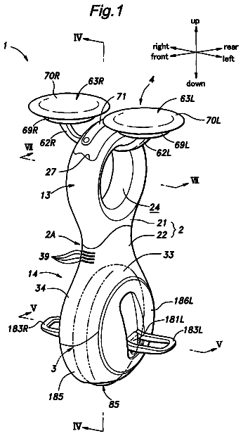
FIG. 1 is a frontal view of an omnidirectional vehicle according to an embodiment of the present invention.
FIG. 2 is a side view of an omnidirectional vehicle according to an embodiment of the present invention.
FIG. 3 is an expanded view of a lower portion of an omnidirectional vehicle according to an embodiment of the present invention.
FIG. 4 is a perspective view of a lower portion of an omnidirectional vehicle according to an embodiment of the present invention.
FIG. 5 is a perspective view of a drive unit (wheel assembly) of an omnidirectional vehicle according to an embodiment of the present invention.
FIG. 6 is a view showing a relative position of a drive unit (wheel assembly) of an omnidirectional vehicle and a free roller according to an embodiment of the present invention.
FIG. 7 is a flowchart showing a processing of a control unit of an omnidirectional vehicle according to an embodiment of the present invention.
FIG. 8 is a diagram showing an inverted pendulum type model representing dynamic behavior of an omnidirectional vehicle according to an embodiment of the present invention.
FIG. 9 is a block diagram showing a processing of step S9 shown in FIG. 7.
FIG. 10 is a block diagram showing a processing of a gain adjusting unit shown in FIG. 9.
FIG. 11 is a block diagram showing a processing of a limiting processor shown in FIG. 10 (or a limiting processor shown in FIG. 12).
FIG. 12 is a block diagram showing a processing of a center-of-gravity point velocity restrictor 76 shown in FIG. 9.
FIG. 13 is a block diagram showing a processing of a posture control calculator 80 shown in FIG. 9.
FIG. 14 is a flowchart showing a processing of a required center-of-gravity point velocity generator 74 shown in FIG. 9.
FIG. 15 is a flowchart showing a subroutine of a processing in step S23 shown in FIG. 14.
FIG. 16 is a flowchart showing a subroutine of a processing in step S24 shown in FIG. 14.
FIG. 17 is a flowchart showing a subroutine of a processing in step S25 shown in FIG. 14.
FIG. 18 is a flowchart showing a second control computation processing in step S23 shown in FIG. 14.
FIG. 19 is a flowchart showing a computational processing in a velocity following mode in step S24 shown in FIG. 14.
FIG. 20 is a flowchart showing a computational processing in a velocity holding mode in step S25 shown in FIG. 14.
FIG. 21 is a diagram showing a relative position of an omnidirectional vehicle 1b, an omnidirectional vehicle 1a running ahead of the omnidirectional vehicle 1b, and a trajectory 400 of the omnidirectional vehicle 1a.
FIG. 22 is a diagram showing a relative position of a vehicle 1b, which ran at a center-of-gravity point velocity of Vb between time .DELTA.T, and a vehicle 1a.
FIG. 23 is a diagram showing a tensional force T1a, a tensional force T1c, a resultant force F of the tensional force T1a and the tensional force T1c, and a trajectory 400 of the vehicle 1a. The tensional force T1a is a tensional force of a cord member 200 applied to three omnidirectional vehicles, which are linked together, and an omnidirectional vehicle 1b and a cord member 300.
FIG. 24 is a block diagram showing a processing of step S9 shown in FIG. 7.
FIG. 25 is a block diagram showing a processing of a posture control calculator 80 shown in FIG. 9 and FIG. 24.
FIG. 26 is a block diagram showing a processing of a posture control calculator 80 shown in FIG. 9 and FIG. 24.
Detailed description of the preferred embodiments
Hereunder, a first embodiment of the present invention is described with reference to the diagrams. First, a configuration of an omnidirectional vehicle according to the present embodiment is described with reference to FIGS. 1-6.
As shown in FIGS. 1 and 2, the omnidirectional vehicle 1 (hereinafter may also be referred to as an inverted pendulum type moving body) according to the present embodiment comprises a payload supporting part 3 of an occupant, who may also be a driver, a drive unit 5, which can move in all directions (i.e., all directions in two dimensional space including the fore-and-aft direction and a lateral direction) on a floor surface while contacting the floor surface, an actuator 7 which supplies to the drive unit 5, a power for driving the drive unit 5, a base body 9 assembled with the payload supporting part 3, the drive unit 5, and the actuator 7, a hook 500a, a hook 500b, a hook base body 510a, a hook base body 510b, a tensional force sensor 520a, and a tensional force sensor 520b.
Here, in the description regarding the present embodiment, the "fore-and-aft direction" and the "lateral direction" respectively refer to a direction which is equal to or approximately matches the fore-and-aft direction and the lateral direction of an upper body of an occupant riding in a standard posture in the payload supporting part 3. Incidentally, a "standard posture" refers to a posture which can be estimated based on a configuration of the payload supporting part 3. This "standard posture" is such that the axis of the upper body of the occupant is aligned roughly in an upper-lower direction. Further, the upper body of the occupant is not twisted and the like.
Here, in FIG. 1, the "fore-and-aft direction" and the "lateral direction" respectively refer to a direction perpendicular to the paper and a lateral direction of the paper. In FIG. 2, the "fore-and-aft direction" and the "lateral direction" respectively refer to a lateral direction of the paper and a direction perpendicular to the paper. Further in the description regarding the present embodiment, a suffix "R" or a suffix "L" are appended to a reference numeral. The suffix "R" is used to refer to a component or a concept corresponding to a right side of the vehicle 1. The suffix "L" is used to refer to a component or a concept corresponding to a left side of the vehicle 1.
The base body 9 comprises a lower part frame 11, which is assembled to the drive unit 5 and the actuating unit 7, and a supporting frame 13, which is provided to extend upwards from an upper end of the lower part frame 11.
A seat frame 15 is fixed to an upper part of the supporting frame 13. The seat frame 15 protrudes towards the front from the supporting frame 13. In addition, a seat 3 is provided on the seat frame 15. A occupant sits on the seat 3. According to the present embodiment, this seat 3 is the riding unit of the occupant. Therefore, the omnidirectional vehicle 1 (hereinafter may also be referred simply as a "vehicle 1") according to the present embodiment moves over a floor surface while the occupant is seated on the seat 3.
In addition, a grip 17R and a grip 17L are placed on the left and right portions of the seat 3. The occupant seated on the seat 3 holds on to the grips 17R, or 17L, if necessary. Each of these grips 17R, 17L fixed respectively on a tip part of a bracket 19R, and a bracket 19L, which extend from the supporting frame 13 (or the seat frame 15).
The lower part frame 11 comprises a pair of cover members 21R and 21L. Each of the cover members 21R and 21L are placed to face one another in a two-pronged form while being separated in a lateral direction. The upper part of these cover members 21R and 21L (i.e., a branching portion of the two-pronged form) are connected via a hinge shaft 23 comprising a shaft center in the fore-and-aft direction. One of the cover members 21R and 21L can move around the hinge shaft 23 relative to the other one of the cover members. In this case, the cover members 21R and 21L are biased towards a direction by a spring (not diagramed) in a direction in which that the lower end portion of the cover members 21R and 21L (i.e., a tip portion of the two-pronged form) narrows towards one another.
Further, a step 25R at an external surface portion of each of the cover members 21R and 21L, a step 25R, on which the right foot of the occupant seated on the seat 3 is placed, and a step 25L, on which the left foot of the occupant is placed, are provided so as to protrude respectively towards the right and the left directions.
In addition, a hook base body 510a is provided at a frontal direction of the supporting frame 13. Further, a hook 500a is provided on the hook base body 510a. Meanwhile, a hook base body 510b is provided at a rear direction of the supporting frame 13. Further, a hook 500b is provided on the hook base body 500b. The hook base body 510a and 510b may be a hinge.
A cord member may be attached to the hook 500a and the hook 500b. Hereinafter, the hook 500a and the hook 500b are collectively referred to as the hook 500. Incidentally, the cord member attached to the hook 500 may be elastic.
A tensional force sensor 520a is provided on the hook base body 510a. The tensional force sensor 520a outputs a signal corresponding to a tensional force of a cord member attached to the hook 500a and a signal indicating a direction in which the tensional force applies. In addition, a tensional force sensor 520b is provided on the hook base body 510b. The tensional force sensor 520b outputs a signal corresponding to a tensional force of a cord member attached to the hook 500b and a signal indicating a direction in which the tensional force applies. Incidentally, the tensional force sensor 520a, 520b may be a single axial sensor detecting an absolute value of the tensional force. In addition, a contact sensor is provided on the hook base body 510a and 510b, which detects a contact. Thus, a signal indicating the direction in which the tensional force is applied may be outputted from the contact sensor. Moreover, the tensional force sensor 520a, 520b may be a hexaxial force sensor and the like. Further, the tensional force sensor 520a, 520b may also be capable of detecting other loads at the same time as detecting a tensional force of a cord member.
The drive unit 5 and the actuator 7 are placed between the cover members 21R, 21L of the lower part frame 11. A configuration of the drive unit 5 and the actuator 7 are described with reference to FIGS. 3-6.
According to the present embodiment, the drive unit 5 is a wheel assembly being a ring-shaped component comprising a rubber elastic material. The cross section of the drive unit 5 is approximately a circle. This drive unit 5 (hereinafter may also be referred to as a wheel assembly 5) can rotate around a center C1 of the circular cross section as indicated in arrow Y1 in FIGS. 5 and 6 due to the elastic deformation of the wheel assembly 5. In particular, the wheel assembly 5 rotates around a circumferential line which passes through the center C1 of the circular cross section and becomes concentric with the shaft core of the wheel assembly 5.
This wheel assembly 5 is placed between the cover members 21R and 21L while the shaft center C2 (a shaft center C perpendicular to the diameter direction of the wheel assembly 5 in general) faces the lateral direction. In addition, the wheel assembly 5 contacts the floor surface with the lower end part of the outer peripheral surface of the wheel assembly 5.
Further, the wheel assembly 5 may perform a movement rotating around the shaft center C2 of the wheel assembly 5 as indicated in arrow Y2 in FIG. 5 (a movement rolling around the floor surface), and a movement rotating around the shaft center C1 of the cross section of the wheel assembly 5. As a result, the wheel assembly 5 may move in all directions on the floor surface by a combination of these rotating movements.
The actuator 7 comprises a free roller 29R and a rotating part 27R, provided between the wheel assembly 5 and the right cover member 21R, a free roller 29L and a rotating part 27L, provided between the wheel assembly 5 and the left cover member 21L, an electric motor 31R placed as an actuator above the rotating part 27R and the free roller 29R, and an electric motor 31L placed as an actuator above the rotating part 27L and the free roller 29L.
A housing of each of the electric motors 31R and 31L is attached respectively to the cover members 21R and 21L. Although not diagrammed, the power source (capacitor) of the electric motors 31R, 31L is provided on appropriate places on the base body 9 such as on the supporting frame 13 and the like.
The rotation member 27R is rotatably supported by the cover member 21R via the supporting axis 33R comprising a shaft center in the lateral direction. Similarly, the rotation member 27L is rotatably supported by the cover member 21L via the supporting axis 33L comprising a shaft center in the lateral direction. In this case, rotational shaft center of the rotation member 27R (the shaft center of the supporting axis 33R) and a rotational shaft center of the rotation member 27L (the shaft center of the supporting axis 33L) are coaxial.
The rotation members 27R, 27L are connected respectively to the output axis of the electric motors 31R, 31L via a power transmission mechanism comprising a decelerating mechanism. The rotation members 27R, 27L are rotated by a power (torque) transmitted by each of the electric motors 31R, 31L. Examples of the power transmission mechanism includes a pulley-type/belt-type device. In other words, as shown in FIG. 3, the rotation member 27R is connected to the output axis of the electric motor 31R via the pulley 35R and the belt 37R. Similarly, the rotation member 27L is connected to the output axis of the electric motor 31L via the pulley 35L and the belt 37L.
Further, the power transmission mechanism may, for example, be a device comprising a sprocket and a linking chain, or, a device comprising a plurality of gears. Further, for instance, the electric motors 31R and 31L may be placed so as to face the rotation members 27R and 27L respectively, so that the output axis of each of the electric motors 31R and 31L is coaxial with the rotation members 27R and 27L respectively. In addition, the output axis of each of the electric motors 31R, 31L may be connected to the rotation members 27R, 27L respectively, via a decelerating device such as a planetary gear drive and the like.
Each of the rotation members 27R and 27L are configured to be the same shape as a circular cone, the diameter of which decreases towards the side of the wheel assembly 5. The outer peripheral surface of the rotation members 27R and 27L are the tapered outer peripheral surfaces 39R and 39L respectively.
A plurality of free rollers 29R are aligned around the tapered outer peripheral surface 39R of the rotation member 27R. Here, the plurality of free rollers 29R are aligned at equal intervals along the circumference of a circle which is coaxial with the rotation member 27R. Further, these free rollers 29R are attached respectively to the tapered outer peripheral surface 39R via the bracket 41R. Moreover, the free rollers 29R are rotatably supported by the bracket 41R.
Similarly, a plurality of free rollers 29L are aligned around the tapered outer peripheral surface 39L of the rotation member 27L. Here, the plurality of free rollers 29L are aligned at equal intervals along the circumference of a circle which is coaxial with the rotation member 27L. Further, these free rollers 29L are attached respectively to the tapered outer peripheral surface 39L via the bracket 41L. Moreover, the free rollers 29L are rotatably supported by the bracket 41L. The number of free rollers 29L is equal to the number of free rollers 29R.
The wheel assembly 5 is placed coaxial with the rotation member 27R and 27L so as to be sandwiched between the free roller 29R at the rotation member 27R side and the free roller 29L at the rotation member 27L side.
In this case, as shown in FIGS. 1 and 6, the shaft center C3 of each of the free rollers 29R and 29L is tilted with respect to the shaft center C2 of the wheel assembly 5. At the same time, the shaft center C3 is placed so as to be tilted with respect to the diameter direction of the wheel assembly 5. Here, the "diameter direction" refers to a radial direction connecting the shaft center C2 and each of the free rollers 29R, 29L, viewing the wheel assembly 5 from a direction of the shaft center C2 of the wheel assembly 5. Further, in this position, the outer peripheral surface of each of the free rollers 29R, 29L are pressed against the inner peripheral surface of the wheel assembly 5 in a diagonal direction.
In more general terms, the free roller 29R at the right side is pressed against the inner peripheral surface of the wheel assembly 5 so that, when the rotation member 27R is driven to rotate around the shaft center C2, a frictional force element in a peripheral direction of the shaft center C2, and a frictional force element in a peripheral direction of the center C1 of the cross section of the wheel assembly 5, may be applied to the wheel assembly 5 at a surface at which the free roller 29R contacts the wheel assembly 5. Here, the frictional force element in the peripheral direction of the shaft center C2 refers to a frictional force element in a direction of a tangential line of an inner circumference of the wheel assembly 5. In addition, the frictional force element in a peripheral direction of the center C1 refers to a frictional force element in a direction of a tangential line of a circular cross section of the wheel assembly 5. The free roller 29L at the left side is configured in a similar manner.
As described above, the cover members 21R and 21L are biased towards a direction by a spring (not diagramed) in a direction in which that the lower end portion of the cover members 21R and 21L (i.e., a tip portion of the two-pronged form) narrows towards one another. Due to this biasing force, the wheel assembly 5 is held between the free roller 29R at the right side and the free roller 29L at the left side. At the same time, the condition of the free rollers 29R and 29L being pressed against the wheel assembly 5 is maintained. In particular, the condition in which frictional force may be applied between each of the free rollers 29R, 29L and the wheel assembly 5.
According to the vehicle 1 configured as described above, when the rotation members 27R, 27L are driven to rotate in the same direction at a same velocity by the electric motors 31R and 31L, the wheel assembly 5 rotates around the shaft center C2 in the same direction as the rotation member 27R, 27L. Therefore, the wheel assembly 5 rolls in a fore-and-aft direction on the floor surface. Thus, the entire vehicle 1 moves in a fore-and-aft direction. Incidentally, in this case, the wheel assembly 5 does not rotate around the center C1 of the lateral cross section.
Further, when the rotation members 27R, 27L are driven to rotate in directions opposite to one another and at a same speed, the wheel assembly 5 rotates around the center C1 of the lateral cross section. As a result, the wheel assembly 5 moves in a direction of the shaft center C2 (i.e., the lateral direction). Further, the entire vehicle 1 moves in the lateral direction. In this case, the wheel assembly 5 does not rotate around the shaft center C2.
Further, when the rotation members 27R, 27L are driven in different velocities in the same direction or in opposite directions, the vehicle wheel 5 rotates around the shaft center C2, and, at the same time, rotates round the center C1 of the lateral cross section of the vehicle wheel 5.
At this time, due to the combination of these rotational movements, the wheel assembly 5 moves in a direction tilted with respect to the fore-and-aft direction and a lateral direction. Moreover, the entire vehicle 1 moves in the same direction as the wheel assembly 5. The direction in which the wheel assembly 5 moves in this case varies depending on the difference between a rotational velocity of the rotation members 27R, 27L. Here, the rotational velocity refers to a rotational velocity vector such that the polarity is defined based on the rotational direction.
Since the moving operation of the wheel assembly 5 is conducted as described above, the velocity with which the vehicle 1 moves and the direction in which the vehicle 1 moves may be controlled by controlling the rotational velocity of each of the electrically operated motors 31R and 31L, and by controlling the rotational velocity of the rotation members 27R and 27L.
Next, a configuration for the moving operation of the vehicle 1 according to the present embodiment is described. In the following description, an xyz coordinate system is envisioned comprising the x axis, referring to the horizontal axis in the fore-and-aft direction, the y axis, referring to the horizontal axis in the lateral direction, and the z axis, referring to the orthogonal axis, as shown in FIGS. 1 and 2. The fore-and-aft direction may also be referred to as the x axis direction. The lateral direction may also be referred to as the y axis direction.
First, a moving operation of the vehicle 1 is described below in general terms. According to the present embodiment, when an occupant who sits on the seat 3 tilts his or her upper body, the base body 9 and the seat 3 tilts towards the direction that the occupant's upper body was tilted. In particular, the tilting of the occupant's upper body refers to a displacement of the position of the center-of-gravity point of a combination of the occupant and the vehicle 1 projected on a horizontal plane. Further, at this time, the moving operation of the wheel assembly 5 is controlled so that the vehicle 1 moves in a direction in which the base body 9 is tilted. For example, when the occupant tilts his or her upper body forward, and also tilts the base body 9 and the seat 3 forward, the moving operation of the wheel assembly 5 is controlled so that the vehicle 1 moves forward.
In other words, according to the present embodiment, the motion of the occupant moving his or her upper body and tilting the base body 9 along with the seat 3 is considered to be a basic maneuvering operation with respect to the vehicle 1. This motion is referred to as an operation request of the vehicle 1. According to this maneuvering operation, the moving operation of the wheel assembly 5 is controlled via the actuator 7.
Here, according to the vehicle 1 based on the present embodiment, a surface at which the wheel assembly 5 contacts the floor surface is a surface at which the entire vehicle 1 contacts the floor surface. This surface at which the wheel assembly 5 contacts the floor surface is a single local region and has a small area (i.e., size) compared to a region obtained by projecting the vehicle 1 and the occupant riding the vehicle 1 in their entirety to the floor surface. A floor reaction force applies only on this single local region. Therefore, in order to prevent the base body 9 from tilting and falling down, it is necessary to move the wheel assembly 5 so that the center-of-gravity point of the occupant and the vehicle 1 in their entirety is positioned approximately right above the surface at which the wheel assembly 5 touches the ground.
Therefore, according to the present embodiment, a target position is referred to as a position of the base body 9 under a condition in which the center-of-gravity point of the occupant and the vehicle 1 in their entirety is positioned approximately right above the center point of the wheel assembly 5 (i.e. the center point along the shaft center C2). In more accurate terms, the center-of-gravity point of the occupant and the vehicle 1 in their entirety is positioned approximately right above the surface at which the wheel assembly 5 contacts the ground. The moving operation of the wheel assembly 5 is controlled so that the actual position of the base body 9 converges with the target position.
Further, when the vehicle 1 is started to move forward and the like, and when the vehicle 1 receives a propulsion force due to the actuator 7 along with an additional external force such as a propulsion force provided by the occupant kicking the floor with his or her foot when necessary in order to increase the velocity at which the vehicle 1 moves, the moving operation of the wheel assembly 5 is controlled so that the velocity of the vehicle 1 increases along with the application of the propulsion force and an additional external force. In more precise terms, the moving operation of the wheel assembly is controlled so that the velocity of the center-of-gravity point of the occupant and the vehicle 1 in their entirety increases. Here, the additional external force provided by the occupant is a propulsion force due to the frictional force created by the back side of the occupant's foot and the floor.
Incidentally, in a condition in which the additional external force is not provided as a propulsion force, the moving operation of the wheel assembly 5 is controlled so that the velocity of the vehicle 1 is once retained at a certain velocity, the velocity of the vehicle 1 then decreases, and the vehicle 1 comes to a halt.
Further, in a condition in which the occupant is not riding the vehicle 1, a target position is referred to as a position of the base body 9 such that the center-of-gravity point of the vehicle 1 in its singular form is positioned approximately right above the center point of the wheel assembly 5 (i.e., the center point of the shaft center C2). In more precise terms, this center-of-gravity point is positioned approximately right above the surface at which the wheel assembly 5 contacts the floor. The moving operation of the wheel assembly 5 is controlled so that the actual posture of the base body 9 converges to the target position, and that the vehicle I may stand on its own without the base body 9 tilting.
According to the present embodiment, in order to control the movement of the vehicle 1 as described above, the vehicle 1 comprises a control unit 50, a tilting sensor 52, a load sensor 54, and a rotary encoder 56R, 56L at appropriate places, as indicated in FIGS. 1 and 2. The control unit 50 comprises an electric circuit unit comprising, for example, a micro computer and a drive circuit unit of the electric motor 31R, 31L. The tilting sensor 52 measures a tilt angle .theta.b with respect to an orthogonal direction (gravitational direction) of a predetermined component of the base body 9. The tilting sensor 52 also measures a rate of change of the tilt angle (=d.theta.b/dt). The load sensor 54 detects whether or not an occupant is boarding the vehicle 1. The rotary encoder 56R, 56L acts as an angle sensor to detect a rotational angle and a rotational angular velocity of an output axis of each of the electric motors 31R and 31L.
In this case, the control unit 50 and the tilting sensor 52 are, for example, assembled to the supporting frame 13 in a condition such that the control unit 50 and the tilting sensor 52 are contained inside the supporting frame 13 of the base body 9. In addition, the load sensor 54 is embedded in the seat 3. Further, each of the rotary encoders 56R and 56L are integrated respectively with the electrically motors 31R and 31L. In addition, each of the rotary encoders 56R and 56L may be integrated respectively with the rotating parts 27R and 27L.
In more detail, the tilting sensor 52 comprises a rate sensor (angular velocity sensor) such as an acceleration sensor and a gyro sensor and the like. The tilting sensor 52 outputs the detection signal of these sensors to the control unit 50. In addition, the control unit 50 carries out a predetermined a predetermined measurement and computation procedure based on an output by the acceleration sensor and the rate sensor of the tilting sensor 52. The predetermined measurement and computation procedure may be a known computation. In this way, the control unit 50 computes a measured value of a tilt angle .theta.b of the component equipped with the tilting sensor 52 with respect to an orthogonal direction and a measured value of a tilting angular velocity .theta.bwdot, which is a rate of change, i.e., a differential of the tilt angle .theta.b. According to the present embodiment, the component equipped with the tilting sensor 52 is the supporting frame 13.
In this case, the measured tilt angle .theta.b (hereinafter, may be referred to as a base body tilt angle .theta.b) each comprises an element .theta.b.sub.--x in the y axis rotational direction (the pitch direction) and an element .theta.b.sub.--y in the x axis rotational direction (the rolling direction). Similarly, the measured tilting angular velocity .theta.bdot (hereinafter, may be referred to as a base body tilting angular velocity .theta.bdot) also comprises an element .theta.bdot_x (=d.theta.b_x/dt) in the y axis rotational direction (the pitch direction) and an element .theta.bdot_y d.theta.b_y/dt) in the x axis rotational direction (the rolling direction).
Further, in the description of the present embodiment, a variable representing a quantity of a movement condition comprising an element in the x axis direction and in the y axis direction or a direction rotating around each of the axes such as the base body tilt angle .theta.b is used. In addition, a variable representing a coefficient and the like relating to the quantity of a movement condition is used. When each element of these variables are expressed separately, a subscript "_x" or "_y" are appended to the reference numeral indicating these variables.
In this case, for variables concerning a translational movement, such as a translational velocity and the like, a subscript "_x" is appended to an element in the x axis direction, while a subscript "_y" is appended to an element in the y axis direction.
Meanwhile, for variables concerning a rotational movement such as an angle, a rotational velocity, i.e., an angular velocity, and an angular acceleration, a subscript "x" is appended to an element in the y axis direction, while a subscript "_y" is appended to an element in the x axis direction, as a matter of convenience, in order to make the subscripts consistent with the subscripts of the variables concerning a translational movement.
Furthermore, when a variable is represented as a pair of elements in the x axis direction and in the y axis direction, or as a pair of elements rotating around the y axis and around the x axis, a subscript "_xy" is appended to the reference numeral indicating these variables. For example, when the base body tilt angle .theta.b is represented as a pair of an element .theta.b_x around the y axis and an element .theta.b_y around the x axis, the subscript "_xy" is used as follows: "base body tilt angle .theta.b_xy."
The description continues in the full USPTO document.
 Lapsed, fee not paid7 drawings