Background of the invention
1. Field of the invention
The present invention relates to a glass run.
2. Related art
In general, a glass run is provided along a circumferential end of a glass opening of a motor vehicle. The glass run is provided with extruded portions which are extruded substantially in straight line (or in an elongated fashion) and molded portions which each connect the extruded portions together in such a state that the extruded portions are connected together at a predetermined angle and includes, for example, a front vertical section, a top section and a rear vertical section so as to follow the shape of the glass opening. In addition, when viewed in a cross-sectional direction, the glass run has a main body which is provided with a base portion, and an interior side wall portion and an exterior side wall portion which extend from the base portion to thereby be formed substantially into a U-shape in cross section, an interior seal lip and an exterior seal lip, the interior seal lip and the exterior seal lip extending into an inner space of the main body from substantially distal ends of both the side wall portions, respectively. In the glass run, the main body is mounted on an inner part of a mounting frame (or a channel portion) which is provided to extend along the glass opening, whereby the door glass is sealed by the pair of seal lips on an internal side and an external side thereof.
In addition, as materials for forming the glass run, ethylene-.alpha.-olefin non-conjugated diene copolymer (EPDM), olefin-based thermoplastic elastomer (TPO) and the like are known.
Incidentally, there occurs from time to time a case where in sliding up and down, a door glass gets loosened or rattles when it is caused to vibrate in a transverse direction of a vehicle. To cope with this problem, conventionally, there has been proposed a technique in which a solid piece, a sponge member or the like is affixed to a predetermined part on an inner surface of the interior side wall portion of the glass run so as to support the interior seal lip which is deflected towards the inside of the vehicle when it is pushed by the door glass. In this case, although the looseness of the door glass is suppressed, since the solid piece or the sponge member needs to be affixed separately, there may be caused a fear that a reduction in working efficiency in manufacturing glass runs and an increase in production cost thereof are called for.
To cope with this problem, there has been proposed another technique in which a sub-lip is provided on the interior side wall portion so as to extend therefrom on the side of the inner space of the main body, so that the sub-lip is made to be brought into contact with an opposite surface (a back surface) of the interior seal lip to a glass contact surface thereof when the door glass is displaced largely towards the inside of the vehicle, so as to suppress the looseness of the door glass (for example, refer to JP-A-2000-33822).
Since the sub-lip and the interior side wall portion can be formed simultaneously by adopting the configuration described in JP-A-2000-33822, the reduction in working efficiency in manufacturing glass runs and increase in production costs thereof can be prevented. In the technique described in JP-A-2000-33822, however, it is not until the door glass is largely displaced towards the inside of the vehicle and as a result, the interior seal lip is largely deflected towards the inside of the vehicle that the interior seal lip is brought into contact with the sub-lip. Namely, the displacement of the door glass towards the inside of the vehicle is still suppressed or absorbed only by the internal seal slip until the interior seal lip is brought into contact with the sub-lip.
Moreover, the part of the back surface of the interior seal lip which is brought into contact with the sub-lip (or the distal end portion of the sub-lip) is set on a root portion side of the interior seal lip, and hence, the sub-lip of JP-A-2000-33822 was not such as to give an effective reaction force to the interior seal lip so as to allow the interior seal lip to return to its normal position.
Because of this, for example, in the event that the interior seal lip wears as a result of sliding contact with the door glass, whereby the elastic force (or the reaction force attempting to push back the door glass) is weakened, once it is pushed by the door glass, the interior seal lip deflects relatively easily towards the inside of the vehicle until it comes into contact with the sub-lip. Because of this, not only the effect to suppress the looseness of the door glass is reduced but also there is caused a concern that the sealing properties are decreased.
Summary of the invention
The invention was made in view of the situations, and an object thereof is to provide a glass run which can suppress the looseness of the door glass while suppressing the reduction in working efficiency in producing glass runs and increase in production costs thereof.
Hereinafter, several aspects of the invention suitable for attaining the object will be described one by one. Note that specific functions and advantages will also be described.
One aspect of the invention provides a glass run adapted to be mounted on an inner part of a mounting frame provided along a door glass opening of a vehicle, comprising:
a main body provided with a base portion, and an interior side wall portion and an exterior side wall portion which extend from the base portion to thereby be formed substantially into a U-shape in cross section;
an interior seal lip extending into an inner space of the main body substantially from a distal end of the interior side wall portion;
an exterior seal lip extending into the inner space of the main body substantially from a distal end of the interior side wall portion;
wherein a sub-lib is provided on the interior side wall portion in a section of the glass run which corresponds to a vertical edge of a door glass so as to extend substantially linearly on a side of the inner space of the main body while inclined towards an inner side of the door glass opening, the sub-lib being formed integrally with the interior side wall portion simultaneously to extrusion of the interior side wall portion, and
a projecting length of the sub-lip is set such that a distal end portion of the sub-lip is brought into abutment with a back surface of the interior seal lip that is opposite to a glass contact surface thereof, when the door glass is inserted into the inner space of the main body.
According to the above aspect of the invention, the sub-lip is provided on the interior side wall portion so as to, extend therefrom substantially linearly on a side of the inner space of the main body while inclined, and when the door glass is inserted into the inner space of the main body, the distal end portion of the sub-lip is made to be brought into abutment (or contact) with the surface of the interior seal lip which is opposite to the glass contact surface thereof (that is, the back surface of the interior seal lip) at the part of the glass run where the door glass is inserted into the inner space of the main body. Because of this, in the event that the door glass attempts to be displaced towards the inside of the vehicle even by a slight amount, the interior seal lip and the sub-lip support, while being deflected, the door glass in such a way as to push it back in cooperation with each other. Consequently, compared to the configuration in which it is not until the door glass is largely displaced towards the inside of the vehicle and as a result, the interior seal lip is largely deflected towards the inside of the vehicle that the interior seal lip is brought into contact with the sub-lip, the sub-lip and the interior seal lip can start to cooperate with each other from the early stage to support the door glass, and hence, the looseness of the door glass can be suppressed in an ensured fashion.
Furthermore, even in the event that the interior seal lip wears to lose its elasticity as a result of sliding contact with the door glass to thereby weaken the elastic force (that is, the reaction force to push back the door glass) of the interior seal lip, the door glass, which attempts to be displaced towards the inside of the vehicle even by a small amount, can be supported by the sub-lip. Consequently, for example, compared to the configuration in which it is not until the door glass is largely displaced towards the inside of the vehicle and as a result, the interior seal lip is largely deflected towards the inside of the vehicle that the interior seal lip is brought into contact with the sub-lip, not only the function and advantage of suppressing the looseness of the door glass can be provided in an ensured fashion but also the reduction in sealing properties can be prevented. Note that the reduction in noise insulating properties can also be prevented by preventing the reduction in sealing properties.
In addition, since the sub-lip and the interior side wall portion are formed simultaneously, for example, compared to the case where the separate member (for example, the solid piece, the sponge member or the like) is affixed to the interior side wall portion, the reduction in working efficiency in manufacturing glass runs and increase in manufacturing costs thereof can be suppressed.
Note that when the door glass enters the inner space of the main body, it is desirable that the distal end portion of the sub-lip is brought into contact with the distal end portion (or a portion in the vicinity of the distal end portion) of the interior seal lip. As this occurs, the advantage that the sub-lip supports the interior seal lip, which is being deflected towards the inside of the vehicle, to thereby suppress the displacement of the door glass in cooperation with the interior seal lip is provided more reliably. Furthermore, by setting such that the distal end portion of the sub-lip and the distal end portion of the interior seal lip are brought into contact with each other, the interior seal lip is allowed to return to its normal position easily by taking a chance of the sub-lip exhibiting the reaction force. In addition, the sub-lip may be provided on the interior side wall portion of the glass run at a part which corresponds to a top side portion of the door glass. Furthermore, a sub-lip may be provided also on the exterior side wall portion so as to extend substantially linearly on a side of the inner space of the main body while inclined towards an inner side of the glass opening. Normally, however, since the normal position of the door glass is offset towards the outside of the vehicle to meet the demand for flush or semi-flush glass, no external sub-lip may be provided particularly.
Note that the description, "the door glass is inserted into the inner space of the main body" is intended to include the fact meaning, "the door glass which slides along a sliding track set in advance for the door glass is inserted into the inner space of the main body without being displaced in the transverse direction of the vehicle."
In the invention, a surface treatment to enhance a slidability of the sub-lip may be applied to the distal end portion of the sub-lip.
According to this aspect of the invention, a fear can be avoided that the distal end portion of the sub-lip and the back surface of the interior seal lip get sticking to each other. In addition, a fear can also be suppressed that the sub-lip and the interior seal lip rub against each other to get worn.
Note that as the surface treatment, such treatments can be raised as forming a sliding layer (for example, a polyethylene resin layer) or applying a coating (for example, a urethane coating) to the surface of the distal end portion of the sub-lip and using a formulation in which a sliding component which enhances the sliding properties is mixed into a material from which the sub-lip is made.
In the invention, a groove portion may be formed along a boundary portion between the sub-lip and the interior side wall portion.
According to this aspect of the invention, in conjunction with the fact that it is formed in a straight line, the sub-lip is made easy to be deformed in such a way as to fall towards the distal end portion side of the interior side wall portion about the boundary portion between the sub-lip and the interior side wall portion. Because of this, in the event that the door glass is largely displaced towards the inside of the vehicle, the interior seal lip and the sub-lip are deformed relatively smoothly while applying a force to push back the door glass. Consequently, a fear can be prevented that deterioration in sliding properties of the door glass is called for due to a force received by the door glass from the sub-lip via the interior seal lip becoming too large.
Note that the groove portion includes conceptually a notched portion, a cut-made portion, a recess, a thinned portion and the like. In addition, the groove portion may be formed at the time of extrusion.
In the invention, a first restricting projection may be provided on the interior seal lip along a part which lies on a distal side with respect to a part which is first brought into contact with the distal end portion of the sub-lip so as to project towards the interior side wall portion, the first restricting projection being formed integrally with the interior seal lip simultaneously to extrusion of the interior seal lip.
In the invention, a projecting length of the first restricting projection may be set to be 0.5 or more times and 1.8 or less times a thickness of the sub-lip.
In the invention, the first restricting projection may be made thicker than the sub-lip.
In the invention, a plurality of projections elongated along a longitudinal direction of the main body may be provided on the interior side wall portion at a part with which the sub-lip can be brought into contact, the projections being formed integrally with the interior side wall portion simultaneously to extrusion of the interior side wall portion.
In the invention, an accommodating recess towards an interior side of the vehicle may be formed at a part of the interior side wall portion with which the sub-lip can be brought into contact such that the projections are formed on a bottom portion of the accommodating recess, and
viewed in a direction perpendicular to a direction in which the interior side wall portion extends, distal ends of the projections may lie on the interior side of the vehicle with respect to a surface of the interior side wall on which the accommodating recess is not formed.
In the invention, a ratio in area on the interior side wall portion of the part where the projections are formed to the part with which the sub-lip can be brought into contact may be 50% or more and 100% or less.
In the invention, a second restricting projection may be provided at a part of the interior seal lip which lies a proximal side with respect to a part which is first brought into contact with the distal end portion of the sub-lip, the second restricting projection being formed integrally with interior seal lip simultaneously to extrusion of the interior seal lip.
In the invention, the second restricting projection may be set such that an angle formed by the interior seal lip and a side portion of the second restricting projection which is on a side of the distal end portion of the interior seal lip constitutes an acute angle.
In the invention, a projecting length of the second restricting projection may be set to be 0.5 or more times and 1.5 or less times a thickness of the sub-lip.
In the invention, the sub-lip may be made from a foamed material and may be formed integrally with the interior side wall portion simultaneously to extrusion of the interior side wall portion.
In the invention, the interior side wall portion may be made from a solid material or a foamed material.
In the invention, the interior side wall portion may be made from an olefin-based thermoplastic elastomer and the sub-lip may be made from a dynamic crosslinking olefin-based thermoplastic elastomer, or
the interior side wall portion and the sub-lip are made from an olefin-based rubber.
Brief description of the drawings
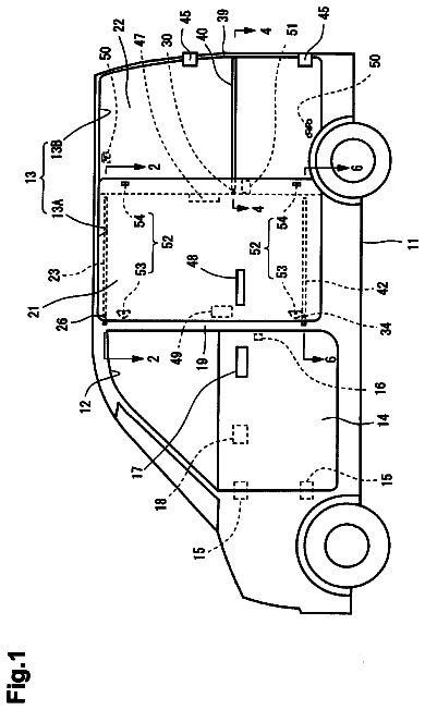
FIG. 1 is a front exemplary view which shows schematically the configuration of a door.
FIG. 2 is a cross-sectional view taken along the line J-J in FIG. 1 which shows the glass run according to the first embodiment.
FIG. 3 is a cross-sectional view of the glass run of one modification of the first embodiment.
FIG. 4 is a cross-sectional view of the glass run of another modification of the first embodiment.
FIG. 5 is a cross-sectional view taken along the line J-J in FIG. 1 which shows the glass run according to the second embodiment.
FIG. 6 is a cross-sectional view of the glass run of one modification of the second embodiment.
FIG. 7 is a cross-sectional view taken along the line J-J in FIG. 1 which shows the glass run according to the third embodiment.
FIG. 8 is a cross-sectional view taken along the line J-J in FIG. 1 which shows the glass run according to the fourth embodiment.
FIG. 9 is a cross-sectional view showing a deformation of the sub-lip according to the fourth embodiment.
FIG. 10 is a cross-sectional view taken along the line J-J in FIG. 1 which shows the glass run according to the fifth embodiment.
Detailed description of the preferred embodiments
First Embodiment
Hereinafter, the first embodiment of the invention will be described by reference to the drawings. FIG. 1 is a front exemplary view which shows schematically the configuration of a door. FIG. 2 is a cross-sectional view taken along the line J-J in FIG. 1 which shows the configuration of a glass run.
As is shown in FIG. 1, a glass run 1 is mounted so as to follow an outer periphery of a glass opening W of an automotive door (a front door in the figure; hereinafter, referred to as a door DF). The glass run 1 is divided as viewed in a longitudinal direction thereof into an extruded portion 2 which corresponds to a top side portion, extruded portions 3, 4 which correspond to front and rear vertical sections, and molded portions 5, 6 (portions which are shaded with dispersed dots in FIG. 1) which connect together end portions of the extruded portions 2, 3 and end portions of the extruded portions 2, 4, respectively. The respective extruded portions 2 to 4 are extruded substantially in a straight line (or in an elongated fashion) by an extruding machine, not shown. The molded portions 5, 6 are molded by a molding apparatus, not shown, in such a state that the two extruded portions 2, 3 and the two extruded portions 2, 4 are connected to each other at predetermined angles, respectively.
As is shown in FIG. 2, the door DF includes an outer panel 51, an inner panel 52 and a molding member 53 which is attached to the panels 51, 52. To be more specific, end portions of the outer panel 51 and the inner panel 52 are bent to the outside of the vehicle and are then superposed one on the other to be formed into a flange portion 55, and the molding member 53 is fixedly attached to the flange portion 55 so formed with a rivet 56. In this embodiment, a groove (hereinafter, referred to a channel portion DC) with a substantially U-shaped cross section is formed by the inner panel 52 and the molding member 53. In addition, the channel portion DC is formed so as to follow an outer circumferential shape of the door DF, and the glass opening W, which is opened and closed by a door glass DG sliding up and down, is defined by this channel portion DC. Then, the glass run 1 is mounted on an inner part of the channel portion DC, and in this embodiment, the channel portion DC constitutes a mounting frame.
In addition, as is shown in FIG. 2, the extruded portion 3, which makes up the front side portion, includes a main body 11 provided with a base portion 14 which is fitted in the channel portion DC, and an exterior side wall portion 15 and an interior side wall portion 16 which extend from the base portion 14 to thereby be formed substantially into a U-shape in cross section, an exterior seal lip 12 and an interior seal lip 13, the exterior seal lip 12 and the interior seal lip 13 extending into an interior (or towards the base portion 14) of the main body 11 from substantially distal ends of the exterior side wall portion 15 and the interior side wall portion 16, respectively. With the glass opening W closed, a surface of the exterior seal lip 12 which constitutes a slide contact surface with the door glass DG (or a surface lying on an inner side of the glass opening W) is brought into press contact with an external surface of the door glass DG, and a surface of the interior seal lip 13 (or a surface lying on the inner side of the glass opening W) is brought into press contact with an inner surface of the door glass DG, whereby the door glass DG is sealed on the external side and the internal side thereof. Note that the extruded portions 2, 4 and the molded portions 5, 6 also each include a main body 11, a pair of seal lips 12, 13 and the like. In addition, the main body 11 and the seal lips 12, 13 of this embodiment are made from TPO (olefin-based thermoplastic elastomer).
In addition, the exterior side wall portion 15 is formed relatively short compared to the interior side wall portion 16, and in conjunction with this configuration, the exterior seal lip 12 is also set relatively small (or short) compared to the internal seal 13, whereby an external side surface of the molding member 53 can be set small, so that not only the appearance is enhanced but also the door glass is situated further outwards in the transverse direction of the vehicle so as to realize flush or semi-flush glass.
Now then, in this embodiment, a sub-lip 31 is provided on the interior side wall portion 16 of the extruded portion 3 which makes up the front vertical section so as to extend substantially linearly therefrom on a side of the inner space of the main body 11 while inclined towards an inner side of the door glass opening W. The sub-lip 31 is formed or extruded together with the interior side wall portion 16 simultaneously to extrusion of the interior side wall portion 16 through extrusion. A back surface of the interior seal lip 13 and a distal end portion of the sub-lip 31 are spaced apart from each other at a part on the extruded portion 3 when the door glass DG is not inserted into the inner space of the main body 11 and, when the door glass DG is inserted into the inner space of the main body 11, at a part on the extruded portion 3 the back surface of the interior seal lip 13 and the distal end portion of the sub-lip 31 are brought into contact with each other. In this embodiment, the distal end portion of the sub-lip 31 is set so as to be brought into contact with a distal end portion of the back surface of the interior seal lip 13.
In addition, in this embodiment, the sub-lip 31 is set such that with the main body 11 mounted in the channel portion DC, an angle formed by a surface (a surface on a base portion 14 side) of the sub-lip 31 and an inner surface of the door glass DG becomes an acute angle (about 35 degrees in this embodiment). However, the extending angle of the sub-lip 31 discussed here is an angle resulting in such a state that no stress is applied to the sub-lip 31. Furthermore, an extending or projecting length of the sub-lip 31 is made shorter than the interior seal lip 13 (in this embodiment, the sub-lip is 4.0 mm long, while the interior seal lip is 15 mm long). In addition, the sub-lip 31 is made thicker than the interior seal lip 13 (in this embodiment, the sub-lip is 0.7 mm thick, while the interior seal lip is 2.0 mm thick). In addition, the angle formed by the surface of the sub-slip 31 and the inner surface of the door glass DG is preferably 25 degrees or more and 45 degrees or less. The length of the interior seal lip 13 is preferably 8 mm or longer and 20 mm or shorter, and the thickness of the interior seal lip 13 is preferably 0.6 mm or thicker and 2.2 mm or thinner. The length of the sub-lip 31 is preferably 3.0 mm or longer and 4.5 mm or shorter, and the thickness of the sub-lip is preferably 0.4 mm thicker and 1.0 mm or thinner.
Additionally, a surface treatment is applied to the distal end portion of the sub-lip 31 in order to increase the sliding properties of the sub-lip 31 relative to the back surface of the interior seal lip 13. Furthermore, a notched portion 32 as a groove portion is formed on a back surface (a surface on a glass opening W side) of the sub-lip 31 at a boundary portion with the interior side wall portion 16. In addition, an accommodating recess 33 is formed on the interior side wall portion 16 for accommodating therein the sub-lip 31 when the sub-lip 31 is largely deflected towards the inside of the vehicle to thereby be shifted closer to the interior side wall portion 16. The notched portion 32 and the recess 33 are formed together with the interior side wall portion 16 simultaneously to extrusion of the interior side wall portion 16. Note that as the surface treatment, as the surface treatment, such treatments can be raised as forming a sliding layer (for example, a polyethylene resin layer) or applying a coating (for example, a urethane coating) to the surface of the distal end portion of the sub-lip 31 and using a formulation in which a sliding component which enhances the sliding properties is mixed into a material from which the sub-lip 31 is made. In particular, when a sliding layer is formed on the surface of the distal end portion of the sub-lip 31 or when a sliding component for enhancing sliding properties is mixed in to a material from which the sub-lip 31 is formed, such a surface treatment can so applied simultaneously to extrusion of the sub-lip 31, thereby making it possible to enhance the workability.
Next, the deforming operation of the interior seal lip 13 and the sub-lip 31 will be described. When the door glass DG is gradually raised to cover the glass opening W, as is shown by chain double-dashed lines in FIG. 2, the door glass DG is inserted into the inner space of the main body 11. As this occurs, the seal lip 12, 13 are pushed by the door glass DG and are slightly deflected, whereby door glass sliding contact surfaces of the seal lips 12, 13 are brought into press contact with the outer and inner surfaces of the door glass DG. In this embodiment, when the door glass DG is inserted into the inner space of the main body 11, the distal end portion of the sub-lip 31 is brought into contact with the back surface of the interior seal lip 13.
In addition, for example, in the event that the door glass DG gets loosened and is displaced towards the inside of the vehicle as the door glass DG is raised further, the interior seal lip 13 is pushed by the door glass DG and is deformed so as to fall towards a proximal end portion side of the interior side wall portion 16 about a connecting portion between the interior seal lip 12 and the interior side wall portion 16. Furthermore, linking with the deformation of the interior seal lip 13 (or being pushed by the interior seal lip 13), the straight-line sub-slip 31 is deformed so as to fall towards a distal end portion side of the interior side wall portion 16 about a boundary portion between the sub-lip 31 and the interior side wall portion 16 while in sliding contact with the back surface of the interior seal lip 13 at the distal end portion thereof. Thus, there may be no occurrence where a reaction force to push back the door glass DG is increased drastically while both the sub-lip 31 and the interior seal lip 13 are deflected together, and because of this, a deterioration in sliding properties of the door glass DG due to the door glass DG being strongly pressed by the sub-lip 31 and the interior seal lip 13 may be avoided.
Note that as on the extruded portion 3, on the extruded portion 4 which makes up the rear vertical section, a sub-lip 31 is also provided on an interior side wall portion 16 so as to extend substantially linearly therefrom towards an inner space of a main body 11 while inclined towards the glass opening W.
As has been described in detail heretofore, according to the embodiment, the sub-lip 31 is provided which extends from the interior side wall portion 16 on a side of the inner space of the main body 11, and the distal end of the sub-lip 31 so provided is made to be brought into contact with the back surface of the distal end portion of the interior seal lip 13 at the part of the glass run where the door glass DG is inserted into the inner space of the main body 11. Because of this, when the door glass DG attempts to be displaced towards the inside of the vehicle even by a small amount, the interior seal lip 13 and the sub-lip 31 cooperate with each other to support the door glass DG so as to push it back while both the interior seal lip 13 and the sub-lip 31 are being deflected. Consequently, compared to the configuration in which it is not until the door glass DG is largely displaced towards the inside of the vehicle and as a result, the interior seal lip 13 is largely deflected towards the inside of the vehicle that the interior seal lip 13 is brought into contact with the sub-lip 31, the sub-lip 31 and the interior seal lip 13 can start to cooperate with each other from the early stage to support the door glass DG, and hence, the looseness of the door glass DG can be suppressed in an ensured fashion. Furthermore, since the distal end portion of the sub-lip 31 and the distal end portion of the seal lip 13 are set so as to be brought into contact with each other, the interior seal lip 13 is allowed to return easily to its normal position by making full use of the reaction force of the sub-lip 31.
Furthermore, even in the event that the elastic force (or the reaction force to push back the door glass DG) of the interior seal lip 13 is weakened as a result of the sliding contact with the door glass DG or deformation resulting from aging, the door glass DG attempting to be displaced towards the inside of the vehicle even by a small amount can be supported by sub-lip 31. Consequently, for example, compared to the configuration in which it is not until the interior seal lip 13 is largely deflected that the interior seal lip 13 and the sub-lip 31 are brought into contact with each other, the function and advantage that the looseness of the door glass DG can be suppressed can be provided in an ensured fashion, thereby making it possible to prevent the reduction in sealing properties. Note that the reduction in noise insulation properties can also be prevented by enabling the prevention of reduction in sealing properties.
In addition, when adopting the configuration in which it is not until the door glass DG is largely displaced towards the inside of the vehicle and as a result, the interior seal lip 13 is largely deflected towards the inside of the vehicle that the interior seal lip 13 and the sub-slip 31 are brought into contact with each other, the aging deformation of only the interior seal lip 13 is prompted, and the reaction force to push back the door glass DG is weakened, whereby it becomes impossible to realize the flush or semi-flush glass in the door glass DG, and moreover, a fear is called for that the door glass DG is attracted towards the inside of the vehicle. In this regard, according to the embodiment, even in the event that the elastic force of the interior seal lip 13 is weakened, since the door glass DG can be supported by the sub-lip 31 when the door glass DG attempts to be displaced towards the inside of the vehicle even by a small amount, the aforesaid drawbacks can be suppressed.
Additionally, since the sub-lip 31 and the interior side wall portion 16 are formed simultaneously, for example, compared to the case where the separate member (for example, a solid piece, a sponge member or the like) is affixed to the interior side wall portion 16, the reduction in working efficiency and increase in production costs can be suppressed.
Furthermore, in the event that a projecting portion (or a thick portion) is provided which projects from the interior side wall portion 16 on a side of the inner space of the main body 11 and is formed together with the interior side wall portion 16 through extrusion, the interior seal lip 13 comes to a so-called bottoming state at the point in time at which the interior seal lip 13 comes into contact with the projecting portion, causing a fear that deterioration in sliding properties of the door glass DG is called for. In this regard, according to the embodiment, since the interior seal lip 13 further continues to be deflected towards the inside of the vehicle even after the sub-lip 31 has come into contact with the sub-lip 31, the occurrence of the aforesaid drawback can be suppressed.
In addition, when the interior seal lip 13 is deflected in such a way as to fall towards the proximal end portion side of the interior side wall portion 16, a force is applied which causes the interior side wall portion 16 to be deformed in such a way as to fall on a side of the inner space of the main body 11. Because of this, for example, when adopting a configuration in which the sub-lip extends on a side of the inner space of the main body 11 while inclined towards a base portion 14 side (or extends substantially parallel to the interior seal lip 13), the sub-lip is deflected towards the inside of the vehicle together with the interior seal lip 13, whereby a fear may be caused that the aforesaid force is enhanced. Namely, a fear is caused that the connecting portion between the interior side wall portion 16 and the interior seal lip 13 and the channel portion DC are separated apart from each other, calling for a fear that the external appearance quality is deteriorated. In this regard, according to the invention, the sub-lip 31 extends substantially linearly on a side of the inner space of the main body 11 while inclined towards the inner side of the glass opening W. Because of this, the sub-lip 31 is deformed in such a way as to fall from its root portion (a proximal end portion) as a starting point, whereby a force is produced which attempts to suppress the aforesaid force. Consequently, the displacement of the connecting portion between the interior side wall portion 16 and the interior seal lip 13 on a side of the inner space of the main body 11 can be suppressed, thereby making it possible to prevent the reduction in external appearance quality.
In addition, the surface treatment is applied to the distal end portion of the sub-slip 31 in order to enhance sliding properties. Because of this, a fear can be avoided that the distal end portion of the sub-slip 31 and the back surface of the interior seal lip 13 get sticking to each other. In addition, a fear can also be suppressed that the sub-lip 31 and the interior seal lip 13 rub against each other to get worn.
Furthermore, the notched portion 32 is formed at the boundary portion between the sub-lip 31 and the interior side wall portion 16. Because of this, the straight-line sub-lip 31 is made easy to be deformed in such a way as to fall towards the distal end portion side of the interior side wall portion 16 about the boundary portion between the sub-lip 31 and the interior side wall portion 16. Because of this, in the event that the door glass DG is largely displaced towards the inside of the vehicle, the interior seal lip 13 and the sub-lip 31 are deformed relatively smoothly while applying a reaction force to push back the door glass DG. Consequently, a fear can be prevented that deterioration in sliding properties of the door glass DG is called for due to a force received by the door glass DG from the sub-lip 31 via the interior seal lip 13 becoming too large.
In addition, the accommodating recess 33 is formed on the interior side wall portion 16 for accommodating therein the sub-slip 31 when the sub-slip 31 is largely deflected towards the inside of the vehicle so as to be attracted towards the interior side wall portion 16. Because of this, a deformation amount of the sub-slip 31 until the sub-slip 31 comes into contact with the interior side wall portion 16 can be increased, thereby making it possible to absorb the looseness of the door glass DG more by an extent equaling such an increase in the deformation amount.
In addition, the sub-lip 31 and the interior seal lip 13 are separated apart from each other in such a state that the door glass DG is not inserted into the inner space of the main body 11. Because of this, an initial load resulting in inserting the door glass DG into the inner space of the main body 11 can be reduced. As a result, an increase in sliding properties of the door glass DG can be realized.
Furthermore, compared to the configuration in which the looseness of the door glass DG is suppressed by extending the interior seal lip 13, the invention can avoid a fear that the door glass DG is attracted towards the outside of the vehicle too close by the interior seal lip 13, the reduction in sliding properties being thereby called for.
Note that the invention is not limited to what has been described heretofore, and hence, the invention may be carried out, for example, as below. Of course, other applications and modifications than those which will be described below can also be included.
While in the embodiments, the sub-lip 31 is provided on the glass run 1 of the type in which the glass run 1 is mounted in the channel portion DC which is provided with the inner panel 52 and the molding member 53, the invention is not limited particularly to such a configuration. For example, the sub-slip 31 may be provided on a glass run which is mounted in a channel portion DC with a substantially U-shaped cross section which is formed in a sashed door as shown in FIG. 3, or the sub-lip 31 may be provided on a glass run which is mounted in a channel portion DC with a substantially U-shaped cross section which is formed in a door such as a pressed-type door as shown in FIG. 4.
In addition, the sub-lip 31 may be provided on the interior sidewall portion 16 of the part (the extruded portion 2) of the glass run 1 which corresponds to the top side portion of the door glass DG. Furthermore, a sub-slip may be provided on the exterior side wall portion 15 so as to extend substantially linearly therefrom on a side of the inner space of the main body 11 while inclined towards the inner side of the glass opening W.
The shape of the notched portion 32 in the embodiments is not limited particularly, and hence, the notched portion 32 is formed into any shape, provided that the shape is such that the sub-slip 31 is allowed to be deformed in such a way as to fall. In addition, the notched portion 32 is such as to prevent the reduction of the sliding properties of the door glass DG due to the rigidity of the sub-lip 31 being too high, and in the event that the sub-lip 31 is allowed to be deformed in such a way as to fall without the provision of the notched portion 32, the notched portion may be omitted. Of course, since the sub-lip 31 is such as to support the door glass DG which is displaced towards the inside of the vehicle in cooperation with the interior seal lip 13, the size and shape of the notched portion 32 can be modified so as to obtain the required elastic force in the sub-lip 31, or the notched portion 32 can be omitted, provided that the required elastic force is obtained.
The description continues in the full USPTO document.
 Lapsed, fee not paid5 drawings