 Lapsed, fee not paid5 drawings
Vehicles & Drones · US 8,564,729 B2
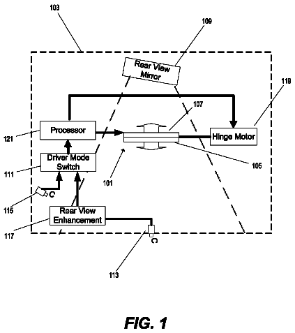
Dual-sided display for vehicle rear-viewing system
A display system for a vehicle including a dual-sided display panel pivotably mounted to the interior ceiling of the vehicle.
US 8,565,953 B2 · Assignee: Toyota Jidosha Kabushiki Kaisha · Inventors: Kato; Norihiko et al.
Sheet 1 of 10 from the published document. All sheets in the USPTO PDF
A power supply system includes a main power storage device and a plurality of sub power storage devices. A converter is connected to a selected one of the sub power storage devices to convert voltage between the selected sub power storage device and an electric power feeding line bidirectionally. The sub power storage device undergoes a connection switching process, and when the last sub power storage device is currently used, then, in accordance with that sub power storage device's SOC and the vehicle's state, a request is generated to disconnect the sub power storage device and a relay is turned off. In doing so, if a process is currently performed for starting or stopping an engine, generating the request is refrained even if a decreased SOC is sensed. Similarly, if a process is performed to disconnect a sub power storage device, and therewhile a request is generated to start/stop the engine, starting the process performed for starting or stopping the engine is refrained.
In recent years as an environmentally friendly vehicle hybrid vehicles have been developed into practical use. A hybrid vehicle has mounted therein an internal combustion engine as a normal vehicular power source, and in addition thereto an electric motor generating force to drive the vehicle, and a power supply system for supplying electric power to drive the motor. The power supply system includes a power storage device. For hybrid vehicles, there has been proposed a configuration charging a vehicle-mounted power storage device by a power supply external to the vehicle (hereinafter also referred to as an "external power supply"), and accordingly, there is a demand for increased distances travelable on electric power stored in the vehicle-mounted power storage device. Hereinafter, charging a vehicle-mounted power storage device by an external power supply will also simply be referred to
1 of 10 drawing sheets so far from the published document, cropped to the drawing. Every sheet is in the USPTO PDF.
What the patent claimed, word for word. All of it is now free to use.
This is a 371 national phase application of PCT/JP2009/060589 filed 10 Jun. 2009, the contents of which are incorporated herein by reference.
The present invention relates generally to hybrid vehicles and methods of controlling the same, and particularly to controlling a power supply system of a hybrid vehicle having a main power storage device and a plurality of sub power storage devices mounted therein.
In recent years as an environmentally friendly vehicle hybrid vehicles have been developed into practical use. A hybrid vehicle has mounted therein an internal combustion engine as a normal vehicular power source, and in addition thereto an electric motor generating force to drive the vehicle, and a power supply system for supplying electric power to drive the motor. The power supply system includes a power storage device.
For hybrid vehicles, there has been proposed a configuration charging a vehicle-mounted power storage device by a power supply external to the vehicle (hereinafter also referred to as an "external power supply"), and accordingly, there is a demand for increased distances travelable on electric power stored in the vehicle-mounted power storage device. Hereinafter, charging a vehicle-mounted power storage device by an external power supply will also simply be referred to as "external charging".
For example, Japanese Patent Laying-Open No. 2008-109840 (PTL 1) describes a power supply system having a plurality of power storage devices (batteries) connected in parallel. The power supply system described in PTL 1 is provided with a voltage converter (a converter) for each power storage device (or battery) as a charging/discharging adjustment mechanism. In contrast, Japanese Patent Laying-Open No. 2008-167620 (PTL 2) describes a power supply device in a vehicle having a main power storage device and a plurality of sub power storage devices mounted therein, that provides a converter associated with the main power storage device and a converter shared by the plurality of sub power storage devices. This configuration can achieve a reduced number of converters and also an increased storable amount of energy.
In particular, the configuration described in PTL 2 has one of the plurality of sub power storage devices selectively connected to the converter to allow the main power storage device and the selected sub power storage device to supply electric power to drive an electric motor for driving a vehicle. In the power supply device when the sub power storage device in use has a decreased state of charge (SOC) a different sub power storage device is connected to the converter to use the plurality of sub power storage devices sequentially to allow stored electric energy to be used to achieve increased electric vehicle (EV) travelable distance.
Patent Literature
PTL 1: Japanese Patent Laying-Open No. 2008-109840 PTL 2: Japanese Patent Laying-Open No. 2008-167620
Technical Problem
In the power supply system described in PTL 2, when all of the sub power storage devices have completely used their stored electricity, positively, electrically disconnecting all of the sub power storage devices from the converter can be expected to allow the power supply system to be subsequently controlled with an increased degree of freedom.
Furthermore, for a hybrid vehicle, traveling depending solely on an output of a motor and that depending on both the output of the motor and that of an engine are selected depending on how the vehicle travels. Accordingly, the engine is operated intermittently as a process is performed to start or stop it while the vehicle is traveling.
When the engine starts/stops, a request is generated to charge/discharge the power supply system. More specifically, to start the engine, the engine is cranked, and to do so, the motor's electric power is output from the power supply system. In stopping the engine, the power supply system receives/outputs the motor's electric power for controlling speed reduction by driving the motor after cutting fuel, and for using regenerative braking immediately before stopping, so as to reduce vibration.
As such, if a disconnection process that accompanies the end of using the last sub power storage device in the power supply system, and starting/stopping the engine are done concurrently, vehicular driving power that can be generated varies, and drivability may be affected.
The present invention has been made to overcome such disadvantage and it contemplates preventing a hybrid vehicle that includes a main power storage device and a plurality of sub power storage devices sharing a voltage converter (a converter) from being negatively affected in drivability by a process performed to disconnect a last sub power storage device as its use ends.
Solution to Problem
The present invention provides a hybrid vehicle including: a motor generating power to drive the vehicle; an internal combustion engine; a main power storage device; an electric power feeding line; a first voltage converter; a plurality of sub power storage devices provided in parallel to each other; a second voltage converter; a connection unit; a control device; and a traveling control unit. The internal combustion engine is configured to be capable of outputting power to drive the vehicle independently of the motor. The electric power feeding line is configured to supply electric power to an inverter that controls and drives the motor. The first voltage converter is provided between the electric power feeding line and the main power storage device and configured to convert voltage therebetween bidirectionally. The second voltage converter is provided between the plurality of sub power storage devices and the electric power feeding line and configured to convert voltage between one of the plurality of sub power storage devices and the electric power feeding line bidirectionally. The connection unit is provided between the plurality of sub power storage devices and the second voltage converter and configured to control connection and disconnection between the plurality of sub power storage devices and the second voltage converter. The control device is operative in a first mode for controlling the connection unit to connect a selected sub power storage device selected sequentially from the plurality of sub power storage devices to the second voltage converter and also disconnect the sub power storage devices other than the selected sub power storage device from the second voltage converter, and the control device is operative in a second mode for controlling the connection unit to disconnect each of the plurality of sub power storage devices from the second voltage converter. The traveling control unit divides and thus assigns a total power required for the hybrid vehicle to power output from the motor and power output from the internal combustion engine. The traveling control unit in a disconnection process performed for disconnecting a sub power storage device of the plurality of sub power storage devices that is last used from the second voltage converter to shift from the first mode to the second mode, prohibits a process performed for starting the internal combustion engine in a stopped state, and the traveling control unit in the disconnection process prohibits a process performed for stopping the internal combustion engine in an operation state.
The present invention provides a method for controlling a hybrid vehicle including: a motor; an internal combustion engine; a main power storage device; an electric power feeding line; a first voltage converter; a plurality of sub power storage devices; a second voltage converter; a connection unit; a control device; and a traveling control unit, as aforementioned. The method includes the steps of: determining whether a disconnection process is currently performed to disconnect a sub power storage device of the plurality of sub power storage devices that is last used from the second voltage converter to shift from the first mode to the second mode; and prohibiting in the disconnection process a process performed for starting the internal combustion engine in a stopped state and a process performed for stopping the internal combustion engine in an operation state.
The present hybrid vehicle and method for controlling the same prohibits performing a process for starting an internal combustion engine and that for stopping the internal combustion engine while a process is performed for disconnecting a sub power storage device. This can prevent electric power from being input/output as the engine starts/stops. As the disconnection process can be performed with the engine starting/stopping process refrained, the power that can be output to drive the vehicle can be free of variation otherwise introduced. This can prevent the disconnection process from negatively affecting the vehicle in drivability.
Preferably the hybrid vehicle further includes: a rotary element configured to have a speed of rotation varying as an output from the internal combustion engine varies; and a protection control unit generating one of a request to start the internal combustion engine and a request to stop the internal combustion engine to prevent the rotary element from excessive rotation. When the protection control unit generates one of the request to start the internal combustion engine and the request to stop the internal combustion engine, then, regardless of whether the disconnection process is currently performed, the traveling control unit permits one of the process performed for starting the internal combustion engine and the process performed for stopping the internal combustion engine. The method further includes the step of permitting one of the process performed for starting the internal combustion engine and the process performed for stopping the internal combustion engine, regardless of whether the disconnection process is currently performed, when the protection control unit generates one of the request to start the internal combustion engine and the request to stop the internal combustion engine.
Thus, when a request to start or stop the internal combustion engine is generated for the purpose of protecting a component, ensuring drivability can be anteceded by starting/stopping the engine to ensure that the component is protected.
Still preferably, the control device includes a disconnection determination unit and a disconnection prohibition unit. The disconnection determination unit is configured to generate a disconnection request requesting that the disconnection process be started, as based on a state of charge of a residual capacity (SOC) of the selected sub power storage device currently used, in the first mode when there is no remaining sub power storage device allowed to be exchanged with the selected sub power storage device currently used. The disconnection prohibition unit is configured to instruct the disconnection determination unit to avoid generating the disconnection request when one of the process performed for starting the internal combustion engine and the process performed for stopping the internal combustion engine is performed. The method further includes the steps of: generating a disconnection request requesting that the disconnection process be started, as based on a state of charge of a residual capacity (SOC) of the selected sub power storage device currently used, in the first mode when there is no remaining sub power storage device allowed to be exchanged with the selected sub power storage device currently used; and providing an instruction to avoid generating the disconnection request, regardless of the state of charge of the selected sub power storage device, when one of the process performed for starting the internal combustion engine and the process performed for stopping the internal combustion engine is performed.
Thus, starting the process for disconnecting a sub power storage device can be prohibited while the process for starting or stopping the internal combustion engine is performed. This further ensures that the process for starting/stopping the internal combustion engine and that for disconnecting the sub power storage device are not performed concurrently.
Preferably the control device further includes a stop-stepping-up-voltage permission unit configured to decrease a lower limit value of a voltage control range for the electric power feeding line in the second mode to be smaller than the lower limit value in the first mode to set the lower limit value at a voltage output from the main power storage device. The method further includes the step of decreasing a lower limit value of a voltage control range for the electric power feeding line in the second mode to be smaller than the lower limit value in the first mode to set the lower limit value at a voltage output from the main power storage device.
This allows the electric power feeding line to have a reduced voltage without forming a short circuit between the main power storage device and the sub power storage devices in the second mode, as the connection unit disconnects all of the sub power storage devices from the converter. Thus in the second mode the first voltage converter's switching loss can be reduced and the hybrid vehicle's energy efficiency can be increased.
The present invention in another aspect provides a hybrid vehicle including: a motor generating power to drive the vehicle; an internal combustion engine; a main power storage device; an electric power feeding line; a first voltage converter; a plurality of sub power storage devices provided in parallel to each other; a second voltage converter; a connection unit; and a control device. The internal combustion engine is configured to be capable of outputting power to drive the vehicle independently of the motor. The electric power feeding line is configured to supply electric power to an inverter that controls and drives the motor. The first voltage converter is provided between the electric power feeding line and the main power storage device and configured to convert voltage therebetween bidirectionally. The second voltage converter is provided between the plurality of sub power storage devices and the electric power feeding line and configured to convert voltage between one of the plurality of sub power storage devices and the electric power feeding line bidirectionally. The connection unit is provided between the plurality of sub power storage devices and the second voltage converter and configured to control connection and disconnection between the plurality of sub power storage devices and the second voltage converter. The control device is operative in a first mode for controlling the connection unit to connect a selected sub power storage device selected sequentially from the plurality of sub power storage devices to the second voltage converter and also disconnect the sub power storage devices other than the selected sub power storage device from the second voltage converter, and the control device is operative in a second mode for controlling the connection unit to disconnect each of the plurality of sub power storage devices from the second voltage converter. The control device includes a disconnection determination unit and a disconnection prohibition unit. The disconnection determination unit is configured to generate a disconnection request indicating that the first mode be shifted to the second mode, as based on a state of charge of a residual capacity of the selected sub power storage device currently used, in the first mode when there is no remaining sub power storage device allowed to be exchanged with the selected sub power storage device currently used. The disconnection prohibition unit is configured to instruct the disconnection determination unit to avoid generating the disconnection request when one of a process performed for starting the internal combustion engine and a process performed for stopping the internal combustion engine is performed.
The present invention in another aspect provides a method for controlling a hybrid vehicle including: a motor; an internal combustion engine; a main power storage device; an electric power feeding line; a first voltage converter; a plurality of sub power storage devices; a second voltage converter; a connection unit; and a control device, as aforementioned. The method includes the steps of: generating a disconnection request indicating that the first mode be shifted to the second mode, as based on a state of charge of a residual capacity of the selected sub power storage device currently used, in the first mode when there is no remaining sub power storage device allowed to be exchanged with the selected sub power storage device currently used; and providing an instruction to avoid generating the disconnection request, regardless of the state of charge of the selected sub power storage device, when one of a process performed for starting the internal combustion engine and a process performed for stopping the internal combustion engine is performed.
The present hybrid vehicle and method for controlling the same prohibits starting a process for disconnecting a sub power storage device while a process is performed for starting an internal combustion engine or a process is performed for stopping the internal combustion engine. This can prevent electric power from being input/output as the engine starts/stops while the process for disconnecting a sub power storage device is performed. The disconnection process is not performed while the engine starting/stopping process is performed, and the power that can be output to drive the vehicle can be free of variation otherwise introduced. This can prevent the disconnection process from negatively affecting the vehicle in drivability.
Preferably the control device further includes a step-up-voltage instruction unit, an electric power limiter unit, a disconnection control unit, and a stop-stepping-up-voltage permission unit. The step-up-voltage instruction unit is configured to instruct the first voltage converter to provide a voltage on the electric power feeding line to be a first voltage higher than at least voltages output from the main power storage device and the plurality of sub power storage devices, respectively, when the disconnection request is generated. The electric power limiter unit is configured to decrease a value of an upper limit on electric power input/output to/from the selected sub power storage device, gradually to zero after the voltage on the electric power feeding line has reached the first voltage. The disconnection control unit instructs the connection unit to disconnect the selected sub power storage device from the second voltage converter and also hold the sub power storage devices other than the selected sub power storage device disconnected from the second voltage converter when the electric power limiter unit sets at zero the value of the upper limit on electric power input/output. The stop-stepping-up-voltage permission unit is configured to decrease a lower limit value of a voltage control range for the electric power feeding line to be smaller than the lower limit value in the first mode to set the lower limit value at a voltage output from the main power storage device after the disconnection control unit disconnects each the sub power storage device from the second voltage converter. The method further includes the steps of: instructing the first voltage converter to provide a voltage on the electric power feeding line to be a first voltage higher than at least voltages output from the main power storage device and the plurality of sub power storage devices, respectively, when the disconnection request is generated; decreasing a value of an upper limit on electric power input/output to/from the selected sub power storage device, gradually to zero after the voltage on the electric power feeding line has reached the first voltage; instructing the connection unit to disconnect the selected sub power storage device from the second voltage converter and also hold the sub power storage devices other than the selected sub power storage device disconnected from the second voltage converter when the step of decreasing sets at zero the value of the upper limit on electric power input/output; and decreasing a lower limit value of a voltage control range for the electric power feeding line to be smaller than the lower limit value in the first mode to set the lower limit value at a voltage output from the main power storage device after the step of instructing disconnects each the sub power storage device from the second voltage converter.
Thus in disconnecting a sub power storage device the electric power feeding line can have a voltage stepped up to a first voltage higher than both a voltage output from the main power storage device and that output from a sub power storage device that is next used and thereafter the sub power storage device that is next used can be connected to the second electric power converter. This can prevent a short circuit from being formed between a sub power storage device and the main power storage device via the electric power feeding line. Furthermore, the connection unit that disconnects all of the sub power storage devices from the converter allows in the second mode the electric power feeding line to have a reduced voltage without a short circuit formed between the main power storage device and the sub power storage devices. Thus in the second mode the first voltage converter's switching loss can be reduced and the hybrid vehicle's energy efficiency can be increased.
Advantageous Effects of Invention
The present invention can thus prevent a hybrid vehicle configured with a power supply including a main power storage device and a sub power storage devices, with a plurality of power storage devices sharing a voltage converter (a converter), from being negatively affected in drivability by a process performed to disconnect a last sub power storage device as its use ends.
FIG. 1 shows a main configuration of a hybrid vehicle in an embodiment of the present invention.
FIG. 2 is a circuit diagram showing in detail a configuration of each inverter shown in FIG. 1.
FIG. 3 is a circuit diagram showing in detail a configuration of each converter shown in FIG. 1.
FIG. 4 is a functional block diagram for illustrating how traveling of a hybrid vehicle is controlled.
FIG. 5 is a flowchart of a general procedure of a process performed to disconnect a selected sub power storage device in a hybrid vehicle in an embodiment of the present invention.
FIG. 6 is a flowchart for illustrating in detail a process performed to determine whether a sub power storage device should be disconnected, as shown in FIG. 5.
FIG. 7 is a flowchart for illustrating in detail a pre-disconnection voltage step up process shown in FIG. 5.
FIG. 8 is a flowchart for illustrating in detail an electric power limit modification process shown in FIG. 5.
FIG. 9 is a flowchart for illustrating in detail a disconnection operation shown in FIG. 5.
FIG. 10 is a flowchart for illustrating in detail a shifting process shown in FIG. 5.
FIG. 11 illustrates a concept of comparing a voltage control range for a power supply line before and after a disconnection process.
FIG. 12 is a waveform diagram of an operation performed in the process for disconnecting a selected sub power storage device in a hybrid vehicle in an embodiment of the present invention.
FIG. 13 is a first flowchart for illustrating a control process for restricting starting/stopping an engine in a hybrid vehicle in an embodiment of the present invention.
FIG. 14 is a second flowchart for illustrating a control process for restricting starting/stopping an engine in a hybrid vehicle in an embodiment of the present invention.
FIG. 15 is a functional block diagram for illustrating a functional portion in a configuration controlling a hybrid vehicle in an embodiment of the present invention, that is provided for the process for disconnecting a selected sub power storage device, and restricting starting/stopping the engine.
Hereinafter reference will be made to the drawings to more specifically describe the present invention in embodiments. In the following description, identical or equivalent components are denoted by identical reference characters and will in principle not be described repeatedly.
FIG. 1 shows a main configuration of a hybrid vehicle in an embodiment of the present invention.
With reference to FIG. 1, a hybrid vehicle 1 includes power storage devices implemented as batteries BA, BB1, BB2, connection units 39A, 39B, converters 12A, 12B, smoothing capacitors C1, C2, CH, voltage sensors 10A, 10B1, 10B2, 13, 21A, 21B, temperature sensors 11A, 11B1, 11B2, current sensors 9A, 9B1, 9B2, an electric power feeding line PL2, inverters 14, 22, motor generators MG1, MG2, a wheel 2, a power split device 3, an engine 4, and a control device 30.
The present embodiment provides a hybrid vehicle power supply system configured to include a main power storage device implemented as battery BA, electric power feeding line PL2 supplying electric power to inverter 14 driving motor generator MG2, converter 12A provided between main power storage device (BA) and electric power feeding line PL2 to serve as a voltage converter converting voltage bidirectionally, batteries BB1, BB2 implementing a plurality of sub power storage devices provided in a manner parallel to each other, and converter 12B provided between the plurality of sub power storage devices (BB1, BB2) and electric power feeding line PL2 to serve as a voltage converter converting voltage bidirectionally. Voltage converter (12B) is connected selectively to one of the plurality of sub power storage devices (BB1, BB2) to convert voltage between the connected sub power storage device and electric power feeding line PL2 bidirectionally.
A sub power storage device (one of BB1 and BB2) and the main power storage device (BA) have their storable capacity set so that for example when they are concurrently used they can output maximum power tolerated for an electric load (22 and MG2) connected to the electric power feeding line. This allows the vehicle without using the engine, i.e., traveling as an EV, to travel with maximum power. If the sub power storage device's state of charge is decreased, the sub power storage device can be exchanged to cause the vehicle to further travel, and if the sub power storage device's electric power has completely been consumed, then, in addition to the main power storage device, the engine can be used to allow the vehicle to travel with maximum power without using the sub power storage device.
Furthermore, such configuration allows converter 12B to be shared between the plurality of sub power storage devices. This can eliminate the necessity of increasing the number of converters to be equal to that of power storage devices. For further increased EV travelable distance, an additional battery can be introduced in parallel with batteries BB1, BB2.
Preferably, this hybrid vehicle has mounted therein a main power storage device and sub power storage devices that are externally chargeable. For this purpose, hybrid vehicle 1 further includes a battery charging device (a charging converter) 6 for connection to an external power supply 8 which is for example a commercial power supply of AC 100V. Battery charging device 6 converts alternate current to direct current and also adjusts voltage to supply electric power charged to a battery. Note that external charging may be achieved by the above described configuration and in addition a system connecting a neutral point of a stator coil of motor generator MG1, MG2 to alternate current power supply or a system causing converters 12A, 12B to together function as an ac/dc conversion device. Alternatively, the external power supply and the vehicle do not contact each other and in that condition they may be electromagnetically coupled together to provide external charging. Smoothing capacitor C1 is connected between a power supply line PL1A and a ground line SL2. Voltage sensor 21A senses voltage VLA across smoothing capacitor C1 and outputs it to control device 30. Converter 12A can step up voltage across smoothing capacitor C1 and supply it to electric power feeding line PL2.
Smoothing capacitor C2 is connected between a power supply line PL1B and ground line SL2. Voltage sensor 21B senses voltage VLB across smoothing capacitor C2 and outputs it to control device 30. Converter 12B can step up voltage across smoothing capacitor C2 and supply it to electric power feeding line PL2.
Smoothing capacitor CH smoothes the voltage stepped up by converter 12A, 12B. Voltage sensor 13 senses voltage VH across smoothing capacitor CH and outputs it to control device 30.
Alternatively, in an opposite direction, converters 12A, 12B can step down voltage VH smoothed by smoothing capacitor CH and supply it to power supply lines PL1A, PL1B.
Inverter 14 receives direct current voltage from converter 12B and/or 12A, converts it to 3 phase alternate current voltage, and outputs it to motor generator MG1. Inverter 22 receives direct current voltage from converter 12B and/or 12A, converts it to 3 phase alternate current voltage, and outputs it to motor generator MG2.
Power split device 3 is a mechanism coupled to engine 4 and motor generators MG1, MG2 to distribute power therebetween. The power split device can for example be a planetary gear mechanism having the three shafts of rotation of a sun gear, a planetary carrier, and a ring gear. In the planetary gear mechanism when two of the three shafts of rotation have their rotation determined, that of the other one shaft of rotation is compulsively determined. These three shafts of rotation are connected to engine 4, motor generators MG1, MG2 at their respective shafts of rotation, respectively. Motor generator MG2 has its shaft of rotation coupled to vehicular wheel 2 by a reduction gear, a differential gear or the like (not shown). Furthermore, power split device 3 may further have a speed reducer incorporated therein for the shaft of rotation of motor generator MG2. In other words, variation of the engine's output not only varies the engine's speed but also acts through the variation of the engine's speed to vary the speed of a rotary element (MG1, MG2 and the like) coupled to power split device 3.
Connection unit 39A includes a system main relay SMR2 connected between the positive electrode of battery BA and power supply line PL1A, a system main relay SMR1 and a limiting resistor R connected in series and connected in parallel with system main relay SMR2, and a system main relay SMR3 connected between the negative electrode of battery BA (a ground line SL1) and node N2.
System main relays SMR1-SMR3 have their conduction/non-conduction states controlled (or are turned on/off) by relay control signals CONT1-CONT3, respectively, issued from control device 30.
Voltage sensor 10A measures voltage VA across battery BA. Furthermore, temperature sensor 11 A measures temperature TA of battery BA, and current sensor 9A measures a current IA input/output to/from battery BA. These measurements are output to control device 30. Based on these measurements, control device 30 monitors a state of battery BA represented by state of charge (SOC).
Connection unit 39B is provided between power supply line PL1B and ground line SL2, and batteries BB1, BB2. Connection unit 39B includes a relay SR1 connected between the positive electrode of battery BB1 and power supply line PL1B, a relay SR1G connected between the negative electrode of battery BB1 and ground line SL2, a relay SR2 connected between the positive electrode of battery BB2 and power supply line PL1B, and a relay SR2G connected between the negative electrode of battery BB2 and ground line SL2.
Relays SRL SR2 have their conduction/non-conduction states controlled (or are turned on/off) by relay control signals CONT4, CONT5, respectively, issued from control device 30. Relays SR1G, SR2G have their conduction/non-conduction states controlled (or are turned on/off) by relay control signals CONT6, CONT7, respectively, issued from control device 30. Ground line SL2 extends through converters 12A, 12B toward inverters 14 and 22, as will be described later.
Voltage sensors 10B1 and 10B2 measure voltages VBB I and VBB2 across batteries BB1 and BB2, respectively. Temperature sensors 11B1 and 11B2 measure temperatures TBB1 and TBB2 of batteries BB1 and BB2, respectively. Current sensors 9B1 and 9B2 measure currents IB1 and IB2 input/output to/from batteries BB1 and BB2, respectively. These sensors' measurements are output to control device 30. Based on these measurements, control device 30 monitors the states of batteries BB1, BB2 represented by state of charge (SOC).
Battery BA, BB1, BB2 can for example be a lead-acid battery, a nickel metal hydride battery, a lithium ion battery or a similar secondary battery, an electric double layer capacitor or a similar capacitor of large capacity, or the like.
Inverter 14 is connected to electric power feeding line PL2 and ground line SL2. Inverter 14 receives voltage stepped up from converter 12A and/or converter 12B, and drives motor generator MG1 for example to start engine 4. Furthermore, inverter 14 returns to converters 12A and 12B the electric power generated by motor generator MG1 by power transmitted from engine 4. At the time, converters 12A and 12B are controlled by control device 30 to operate as step down converters.
Current sensor 24 senses a current that flows to motor generator MGI as a motor current value MCRT1, and outputs motor current value MCRT1 to control device 30.
Inverter 22 is connected to electric power feeding line PL2 and ground line SL2 in a manner parallel with inverter 14. Inverter 22 receives direct current voltage from converters 12A and 12B, converts it to 3 phase alternate current voltage, and outputs it to motor generator MG2 driving wheel 2. Furthermore, inverter 22 returns to converters 12A and 12B the electric power generated by motor generator MG2 as the vehicle is regeneratively braked. At the time, converters 12A and 12B are controlled by control device 30 to operate as step down converters.
Current sensor 25 senses a current that flows to motor generator MG2 as a motor current value MCRT2, and outputs motor current value MCRT2 to control device 30.
Control device 30 is constituted by an electronic control unit (ECU) having a central processing unit (CPU) and a memory (not shown) incorporated therein, and in accordance with a map and a program stored in the memory, uses each sensor's measurement to perform an operation process. Note that control device 30 may have a portion configured to allow an electronic circuit or similar hardware to perform predetermined arithmetic and logical operations.
More specifically, control device 30 receives torque command values for motor generators MG1, MG2, respectively, the motor generators' respective speeds, the voltage VBA, VBB1, VBB2, VLA, VLB, VH values, motor current values MCRT1, MCRT2, and a start signal IGON and accordingly controls converters 12A, 12B and inverters 14, 22.
Control device 30 outputs control signals PWUA, PWUB instructing converters 12A, 12B to step up voltage, control signals PWDA, PWDB instructing converters 12A, 12B to step down voltage, control signals PWFA, PWFB instructing converters 12A, 12B to hold voltage, and a shutdown signal (not shown) prohibiting converters 12A, 12B from operation.
Furthermore, control device 30 outputs a control signal PWMI1 instructing inverter 14 to convert direct current voltage output from converters 12A, 12B to alternate current voltage for driving motor generator MG1, and a control signal PWMC1 instructing inverter 14 to convert alternate current voltage generated by motor generator MG1 to direct current voltage and return it toward converters 12A, 12B for regeneration.
Similarly, control device 30 outputs a control signal PWMI2 instructing inverter 22 to convert direct current voltage to alternate current voltage for driving motor generator MG2, and a control signal PWMC2 instructing inverter 22 to convert alternate current voltage generated by motor generator MG2 to direct current voltage and return it toward converters 12A, 12B for regeneration.
FIG. 2 is a circuit diagram showing in detail a configuration of inverters 14 and 22 shown in FIG. 1.
With reference to FIG. 2, inverter 14 includes a U phase arm 15, a V phase arm 16, and a W phase arm 17. U phase arm 15, V phase arm 16, and W phase arm 17 are connected between electric power feeding line PL2 and ground line SL2 in parallel.
U phase arm 15 includes insulated gate bipolar transistor (IGBT) devices Q3, Q4 connected in series between electric power feeding line PL2 and ground line SL2, IGBT devices Q3, Q4, and their respective anti-parallel diodes D3, D4. Diode D3 has its cathode connected to IGBT device Q3 at the collector, and its anode to IGBT device Q3 at the emitter. Diode D4 has its cathode connected to IGBT device Q4 at the collector and its anode to IGBT device Q4 at the emitter.
V phase arm 16 includes IGBT devices Q5, Q6 connected in series between electric power feeding line PL2 and ground line SL2, and their respective anti-parallel diodes D5, D6. IGBT devices Q5, Q6 and anti-parallel diodes D5, D6 are connected similarly as done in U phase arm 15.
W phase aim 17 includes IGBT devices Q7, Q8 connected in series between electric power feeding line PL2 and ground line SL2, and their respective anti-parallel diodes D7, D8. IGBT devices Q7, Q8 and anti-parallel diodes D7, D8 are also connected similarly as done in U phase aim 15.
Note that in the present embodiment an IGBT device is indicated as a representative example of a power semiconductor switching element controllable to be turned on/off. In other words, it is also replaceable with a bipolar transistor, a field effect transistor or a similar power semiconductor switching element.
Each phase arm has an intermediate point connected to motor generator MGI at each phase coil at each phase end. In other words, motor generator MG1 is a 3 phase permanent magnet synchronous motor and the three U, V, W phase coils each have one end connected together to an intermediate point. The U phase coil has the other end connected to a line UL drawn from a connection node of IGBT devices Q3, Q4. The V phase coil has the other end connected to a line VL drawn from a connection node of IGBT devices Q5, Q6. The W phase coil has the other end connected to a line WL drawn from a connection node of IGBT devices Q7, Q8.
Inverter 22 shown in FIG. 1 is different in that it is connected to motor generator
MG2. However, its internal circuit configuration is similar to inverter 14. Accordingly it will not be described repeatedly in detail. Furthermore, FIG. 2 shows an inverter receiving control signals PWMI, PWMC. This is to avoid complexity. Specifically, as shown in FIG. 1, different control signals PWMI1, PWMC1 and control signals PWMI2, PWMC2 are input to inverters 14, 22, respectively.
FIG. 3 is a circuit diagram showing in detail a configuration of converters 12A and 12B shown in FIG. 1.
With reference to FIG. 3, converter 12A includes a reactor L1 having one end connected to power supply line PL1A, IGBT devices Q1, Q2 connected in series between electric power feeding line PL2 and ground line SL2, and their respective anti-parallel diodes D1, D2.
Reactor L1 has the other end connected to IGBT device Q1 at the emitter and to IGBT device Q2 at the collector. Diode D1 has its cathode connected to IGBT device Q1 at the collector and its anode to IGBT device Q1 at the emitter.
The description continues in the full USPTO document.
About 6,401 words. The USPTO PDF has it with every drawing.
Fees are due 3.5, 7.5 and 11.5 years after grant. This patent expired on October 22, 2025, so the fee marked "not paid" was the one that went unpaid.
HYBRID VEHICLE AND METHOD FOR CONTROLLING THE SAME
Filed Jun 2009 · published Jan 2012Hybrid vehicle and method for controlling the same
Filed Jun 2009 · granted Oct 2013Earlier publications, parents and continuations. None of them can still be enforced, or this patent would not be listed.
Prior art cited by the examiner or applicant. Useful when you check your own idea for novelty.
Everything on this page comes from the documents linked above.


