Technical field
The present invention relates to a wireless communication system, and more particularly, to an MS apparatus and method for transmitting signals using an FFR scheme.
Background art
In a Orthogonal Frequency Division Multiple Access (OFDMA) system of multi-carrier scheme, resources are allocated in units of subchannels, each including subcarriers. A plurality of users separately share all subcarriers, so multi-user diversity gain is obtained in frequency region. In an OFDMA broadband mobile Internet access system such as WiBro, all cells reuse the same frequency and an Adaptive Modulation & Coding (AMC) scheme is applied according to received signal strength and interference between neighbor cells due to reuse of the same frequency, thereby maximizing throughput.
However, in such a system having a Frequency reuse Factor (FRF) of 1, inter-cell interference is severe and throughput reduction is inevitable at edges (i.e., boundaries) of cells or sectors. This may cause service outage. In a method for improving performance at cell edges when a frequency reuse factor of 1 is used, all subcarriers are orthogonally divided into a number of frequency partitions and the frequency partitions are appropriately arranged in cells such that a specific frequency partition is not used or is used at low power in each cell, thereby reducing interference of the same channel between neighbor cells. This method is referred to as a Fractional Frequency Reuse (FFR) scheme.
In order to apply FFR to an actual system, a band to be used in each cell may be determined based on frequency partitions arranged in the cell according to location information of each Mobile Station (MS). In actual situations, a signal to interference ratio may be dynamically reflected in determining which frequency partitions are to be used for each cell among a band allocated to the cell since the signal to interference ratio constantly varies in the same band due to movement of the MS, fading, etc.
In order to dynamically use resources taking into consideration the signal to interference ratio or the like when partial frequency partitions have been allocated to each cell as described above, it is necessary to take into consideration fairness between users in addition to the given Frequency Reuse Factor (FRF).
When all subcarriers are orthogonally divided into a number of frequency partitions in the OFDMA system as described above, various types of FFR schemes may be taken into consideration to allow cells to share these frequency partitions. The following is a description of the concept and characteristics of such FFR schemes.
As the FRF approaches 1, inter-cell interference due to use of the same channel at cell edges may increase, thereby reducing communication performance, although the size of a band that is available in the cell increases. On the other hand, as the FRF increases, the size of the available band decreases, thereby reducing band efficiency, although inter-cell interference due to use of the same channel decreases.
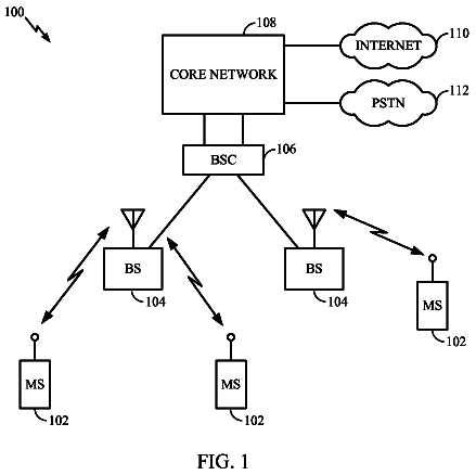
FIG. 1 illustrates an example FFR scheme.
Referring to FIG. 1, FFR is a method for increasing cell capacity and user Quality of Service (QoS). In the FFR scheme, services are provided to users located near a Base Station (BS) using a frequency reuse factor (FRF) of 1 (i.e., using all subcarriers) to maximize total cell capacity since the level of inter-cell interference will be relatively low for users located near the BS from the viewpoint of the entire cell. In the case where the FRF 1 is used, a FRF of 3 is used for cell-edge users expected to undergo a high inter-cell interference level (i.e., not all subcarriers are used but instead part of the bands of FRF 3 is used for each sector), thereby reducing inter-cell interference to provide high quality services.
FFR is classified into hard FFR in which frequency bands used by cell-edge users of other cells are not used and soft FFR in which such frequency bands are also used with restriction of power and specific conditions.
The soft FFR scheme is a general concept including hard FFR. In the soft FFR scheme, neighbor cells set different transmission power levels for each frequency partition, thereby increasing overall cell capacity. Here, the soft FFR scheme becomes a hard FFR scheme if transmission power is set to 0.
FIG. 2 illustrates example hard and soft FFR schemes.
Referring to FIG. 2, in the case of the hard FFR scheme, only specific frequency bands are used among frequency bands of FFR 1/3 in each cell. On the other hand, it can be seen that, in the case of the soft FFR scheme, all frequency bands of FFR 1/3 are at different power levels in each cell. For example, the power level of the same frequency band of FFR 1/3 may be different for each cell. In addition, each cell may have different power levels for the frequency bands of FFR 1/3.
When the FFR scheme is applied, each frequency band generally has a different power level as shown in FIG. 2. The present invention suggests how to set a power level for each FFR group or each frequency partition and how to perform signaling in downlink and uplink.
Disclosure
Technical Problem
An object of the present invention is to provide a method for transmitting signals in a wireless communication system.
Another object of the present invention is to provide an MS apparatus for transmitting signals in a wireless communication system.
Objects of the present invention are not limited to those described above and other objects will be clearly understood by those skilled in the art from the following description.
Technical Solution
A method for transmitting, at a mobile station, signals in a wireless communication system to achieve the objects of the present invention includes receiving information a specific frequency partition allocated to the mobile station according to a fractional frequency reuse scheme, receiving parameter information for controlling an inter-cell interference level for each frequency partition from a base station, determining a transmission power level for the allocated specific frequency partition using the received information, and transmitting a signal to the base station at the determined transmission power level.
The method may further include receiving, from the base station, at least one of a minimum required Signal to Interference plus Noise Ratio (SINR), a factor value according to the number of receive antennas of the base station, and a value indicating a MAC power control mode.
The inter-cell interference control parameter includes default inter-cell interference control parameter information representing a default value of each frequency partition and relative adjustment inter-cell control parameter information representing a relative difference value from the default cell interference control parameter value of a specific frequency partition.
A frequency partition which uses the default inter-cell interference control parameter alone may be determined according to a number of predefined frequency partitions.
When the number of predefined frequency partitions is 1, the frequency partition which uses the default inter-cell interference control parameter alone may correspond to a frequency partition of a frequency reuse factor of 1.
When the number of predefined frequency partitions is 3, the frequency partition which uses the default inter-cell interference control parameter alone may correspond to a specific frequency partition among frequency partitions of the frequency reuse factor of 3.
On the other hand, a specific frequency partition among frequency partitions of a frequency reuse factor of 3 may be different for each cell.
The default inter-cell interference control parameter value is equal for all frequency partitions or for a specific frequency partition group among the all frequency partitions or may be different for each frequency partition.
The default inter-cell interference control parameter value may be signaled in 4 bits from the base station.
The base station may notify the mobile station of the specific frequency partition among the frequency partitions of a frequency reuse factor of 3 is notified through broadcast signaling, or individual signaling of each mobile station.
The specific frequency partition among the frequency partitions of a frequency reuse factor of 3 may be determined as a cell Identifier (ID) function.
The relative adjustment inter-cell interference control parameter value may be used for a specific frequency partition among frequency partitions of a frequency reuse factor of 3.
The relative adjustment inter-cell interference control parameter value may be signaled in 2 or 3 bits from the base station.
The step of determining the transmission power level may include determining transmission power additionally taking into consideration a downlink signal to interference plus noise power ratio (SINR) measured at the mobile station.
The determined transmission power level may be a transmission power level determined for each stream and for each subcarrier.
The inter-cell interference control parameter may be determined through coordination between the base stations. The inter-cell interference control parameter may also be signaled to the mobile station through a control channel or message, wherein the control channel may be one of a superframe header, an uplink Advanced-MAP Information Element (A-MAP IE), and Additional Broadcast Information (ABI).
Advantageous Effects
According to the present invention, when uplink transmission is performed, it is possible to improve system throughput and cell edge-user throughput and to efficiently perform inter-cell interference level control.
Advantages of the present invention are not limited to those described above and other advantages will be clearly understood by those skilled in the art from the following description.
Description of drawings
The accompanying drawings, which are included to provide a further understanding of the invention, illustrate embodiments of the invention and together with the description serve to explain the principle of the invention.
In the drawings:
FIG. 1 illustrates an example FFR scheme.
FIG. 2 illustrates example hard and soft FFR schemes.
FIG. 3 illustrates an example FFR scheme.
FIG. 4 illustrates an example wherein a different SINR_target value is applied in each frequency partition when the FFR scheme is applied.
FIG. 5 illustrates the operation of a soft FFR scheme in downlink.
FIG. 6 illustrates an example operation scenario of a base station and a mobile station when a soft FFR scheme is applied in uplink.
FIG. 7 illustrates an example operation scenario of a base station and a mobile station when a soft FFR scheme is applied in uplink.
FIG. 8 illustrates duality of a downlink transmission power level and an uplink target IoT level.
FIG. 9 illustrates an example wherein a different transmission power value is used for each frequency partition in the case where an uplink FFR scheme is applied.
FIG. 10 illustrates an example wherein a sounding channel configuration is transmitted in one OFDM symbol at intervals of a predetermined frame period.
FIG. 11 is a block diagram illustrating a configuration of a preferred embodiment of a mobile station that can transmit signals according to the present invention.
Mode for invention
Reference will now be made in detail to the preferred embodiments of the present invention with reference to the accompanying drawings. The detailed description, which will be given below with reference to the accompanying drawings, is intended to explain exemplary embodiments of the present invention, rather than to show the only embodiments that can be implemented according to the invention. The following detailed description includes specific details in order to provide a thorough understanding of the present invention. However, it will be apparent to those skilled in the art that the present invention may be practiced without such specific details. For example, although the following description will be given with reference to specific terms, the present invention is not necessarily limited to the specific terms and other terms may also be used to indicate the same meanings. The same reference numbers will be used throughout this specification to refer to the same or like parts.
The expression "a portion includes a specific component" used throughout this specification indicates that the portion may also include other components, rather than includes the specific component alone, unless explicitly stated otherwise.
Technologies described below can be used in a variety of communication systems, which can provide a variety of communication services such as voice and packet data services. Communication system technologies can be used in downlink or uplink. The term "Base Station (BS)" may be replaced with another term such as "fixed station", "Node B", "eNode B (eNB)", "access point", or "ABS". The term "Mobile Station (MS)" may also be replaced with another term such as "User Equipment (UE)", "Subscriber Station (SS)", "Mobile Subscriber Station (MSS)", "AMS", or "mobile terminal".
The term "transmitting end" refers to a node that transmits data or audio services and "receiving end" refers to a node that receives data or audio services. Thus, in uplink, the MS may be a transmitting end and the BS may be a receiving end. Similarly, the MS may be a receiving end and the BS may be a transmitting end in downlink.
A Personal Digital Assistant (PDA), a cellular phone, a Personal Communication Service (PCS) phone, a Global System for Mobile (GSM) phone, a Wideband CDMA (WCDMA) phone, or a Mobile Broadband System (MBS) phone may be used as the MS in the present invention.
The embodiments of the present invention can be supported by standard documents of at least one of the Institute of Electrical and Electronics Engineers (IEEE) 802 system, the 3GPP system, the 3rd Generation Partnership Project Long Term Evolution (3GPP LTE) system, and the 3GPP2 system which are wireless access systems. That is, steps or portions that are not described in the embodiments of the present invention for the sake of clearly describing the spirit of the present invention can be supported by the standard documents. For all terms used in this disclosure, reference can be made to the standard documents. Especially, the embodiments of the present invention can be supported by P802.16-2004, P802.16e-2005, P802.16Rev2, and P802.16m AWD or P802.16m draft, which are standard documents of the IEEE 802.16 system.
Specific terms used in the following description are provided for better understanding of the present invention and can be replaced with other terms without departing from the spirit of the present invention.
The term "Base Station (BS)" used in the present invention conceptually includes "cell" or "sector", and can also be referred to as a cell or sector.
The present invention suggests how to set a power level for each FFR group or each frequency partition and how to perform signaling in downlink and uplink.
In addition, this specification describes a power control method for improving performance of cell-edge user and performance of cell or sector system using a Fractional Frequency Reuse (FFR) scheme in uplink. An object of this power control method is to reduce interference and to achieve minimum cell-edge user performance. Another object of this power control method is to improve performance in multi-user MIMO environments while maintaining the same level of interference as in the single-user scheme. One main feature of this power control method is to minimize control signaling in order to reduce overhead while achieving the same performance.
A system that uses the FFR scheme can use at least two frequency partitions. When two or more frequency partitions are present, the frequency partitions may undergo different communication environments such as different channel characteristics, different interference characteristics. This can be used for specific purposes. That is, when a Mobile Station (MS) is in a bad channel condition, the MS can achieve an improvement in performance by using resources of frequency and time regions in which a relatively low level of interference is measured.
FIG. 3 illustrates an example FFR scheme.
Referring to FIG. 3, four frequency partitions may be present and relatively large power may be used in a specific one of the three FFR 1/3 regions if the soft FFR scheme is used. It is preferable that the FFR 1/3 region be used for a specific MS which is in a bad channel condition. It is necessary to take into consideration the amount of interference caused to other cells or sectors when performing power and user allocation to the remaining two FFR 1/3 regions. This is because the benefits of the FFR scheme may not be achieved in the case where the resource allocation of the regions is not appropriate. In the present invention, it is possible to apply an algorithm suitable for each frequency partition in order to support a system, to which the FFR scheme is applied, to efficiently support such allocation. This algorithm may operate based on an open-loop power control scheme.
Since propagation loss, interference, noise, and the like may operate as factors reducing signal quality, to obtain signal quality required for the receiving end, it is necessary to appropriately control transmission power so as to overcome such signal quality reduction factors.
Power control generally satisfies the signal quality required for the receiving end by compensating for pathloss (or propagation loss), interference, and noise between the BS and the MS. Accordingly, transmission power may be determined taking into consideration a target Signal to Interference plus Noise Ratio (SINR), noise (N), interference (I), and pathloss (PL) or may be determined taking into consideration a target Carrier to Interference plus Noise Ratio (CINR), noise (N), interference (I), and pathloss (PL) as expressed in the following Mathematical Expression 1. P.sub.tx=f(SINR.sub.target,N,I,PL)or f(CINR.sub.target,N,I,PL) [Mathematical Expression 1]
Mobile communication system may have pathloss according to distance since electromagnetic waves are used as a transmission means. Such pathloss may be caused by attenuation that electromagnetic or radio waves undergo until arriving at a receive antenna after being transmitted from a transmit antenna, and may also be caused by changes in the distance between the transmitting and receiving ends due to the movement of the moving body or ambient environments.
Uplink power control in the IEEE 802.16e system is briefly described as follows. In the IEEE 802.16e system, system performance can be improved by performing power control taking into consideration not only the SINR or CINR, pathloss, interference, and noise but also offsets due to the BS and the MS (.DELTA.offset_MS and .DELTA.offset_BS) according to system characteristics. This can be represented by the following Mathematical Expression 2. P.sub.tx=SINR+(I+N)+PL+.DELTA..sub.offset.sub.--.sub.MS+.DELTA..sub.offse- t.sub.--.sub.BS[dBm] [Mathematical Expression 2]
Since interference due to neighbor cell is factor deteriorating system performance, it is necessary to control transmission power so as to overcome interference through power control in wireless communication systems. Transmission power is generally proportional to interference power. That is, increasing the transmission power to overcome interference causes an increase of interference caused to neighbor cells, which then may cause the serving cell to receive stronger interference from the neighbor cells. Accordingly, there is a need to provide a power control method which appropriately controls interference caused to neighbor cells while ensuring signal quality required for the receiving end.
Fractional power control compensates only for part of pathloss using a power control method for suppressing inter-cell interference (ICI). That is, if transmission power is reduced by compensating only for part of pathloss, it is possible to reduce interference caused to neighbor cells, resulting in a reduction of interference received from neighbor cells. Such power control may be represented by the following Mathematical Expression 3. P.sub.tx=SINR+(I+N)+.alpha.PL[dBm],0<.alpha..ltoreq.1 [Mathematical Expression 3]
Here, .alpha. is a factor to compensate for part of pathloss.
The following is a description of a power control method to achieve a target interference level.
A target interference level may be used as a method for minimizing interference caused to neighbor cells while satisfying signal quality required for the receiving end. The target interference level is a level of interference to satisfy required signal quality at a receiving end and may be expressed using a variety of terms including inter-cell interference terms (or elements) such as IoT, SINR, and CINR.
In the case inter-cell interference level in a cell or sector is greater than a level of required signal quality, the receiving end may request a neighbor cell or sector to restrict inter-cell interference and this request may be signaled through a backbone link. Power control may be performed through inter-cell coordination between BSs rather than through an individual request.
A BS of a cell or sector has received a request to perform power control for limiting or reducing inter-cell interference or a BS performs inter-cell coordination with other BSs, the BS may control transmission power of the transmitting end as expressed by the following Mathematical Expressions in order to reduce inter-cell interference caused to neighbor cells or sectors. P.sub.tx=(1-.alpha.)P.sub.IoT.sub.target/.alpha.P.sub.intra.sub.--.sub.tx where,0.ltoreq..alpha..ltoreq.1 if .alpha.=1,IoT.sub.tar.gtoreq.IoT.sub.e .alpha.=0,IoT.sub.tar<IoT.sub.e [Mathematical Expression 4] P.sub.tx=.alpha.P.sub.IoT.sub.target+(1-.alpha.)P.sub.intra.sub.--.sub.tx where,0.ltoreq..alpha..ltoreq.1 if .alpha.=1,IoT.sub.tar<IoT.sub.e .alpha.=0,IoT.sub.tar.gtoreq.IoT.sub.e [Mathematical Expression 5]
Here, IoT.sub.tar denotes a target level of inter-cell interference required from a neighbor cell or sector, P.sub.intra.sub.--.sub.tx denotes transmission power when inter-cell interference is not taken into consideration, IoT.sub.e denotes an estimated level of interference caused to a neighbor cell or sector, and P.sub.IoT.sub.target denotes a transmission power level for satisfying IoT.sub.tar.
Here, `N` may be omitted in the case where IoT.sub.term does not include noise unlike its original definition. P.sub.intra.sub.--.sub.tx may be represented as P.sub.intra.sub.--.sub.tx=SINR.sub.tarPL.sub.s(I+N) and may also be represented as P.sub.intra.sub.--.sub.tx=SINR.sub.tarPL.sub.s(I+N).DELTA..sub.offset.sub- .--.sub.MS.DELTA..sub.offset.sub.--.sub.BS taking into consideration BS offset and MS offset. The inter-cell interference power I.sub.inter is received as
##EQU00001## and IoT.sub.e is received as
.apprxeq. ##EQU00002## If N>>1,
##EQU00003## so that P.sub.IoT.sub.target=IoT.sub.tarPL.sub.sN.
In the case of Open Loop Power Control (OLPC) among power control methods for controlling inter-cell interference in which power control is performed by the MS, the BS may transmit, to the MS, an interference level (IoT.sub.tar) for controlling inter-cell interference such as a target IoT received from a neighbor cell or sector (or a target IoT determined through coordination between BSs or a target IoT randomly determined between BSs).
In the case where a system bandwidth is divided into multiple frequency partitions as in the IEEE 802.16m system, a different interference level may be transmitted for each frequency partition or to each MS.
The interference level (target IoT, i.e., IoT.sub.tar) for each frequency partition may be determined as in the following Mathematical Expression 6 or 7. IoT.sub.tar=.omega.IoT.sub.default[dB] [Mathematical Expression 6] IoT.sub.tar=.omega..+-.IoT.sub.default[dB] [Mathematical Expression 7]
In Mathematical Expression 6 or 7, .omega. denotes a weight factor for setting a target IoT and can be obtained using the following equation. The following is a description of various methods for setting the target IoT. In a first method, the target IoT can be represented by the following Mathematical Expression 8. IoT.sub.tar=(1-.gamma.)IoT.sub.min+.gamma.IoT.sub.default [Mathematical Expression 8]
Here, a list that is signaled by the BS may include a minimum target IoT (IoT.sub.min), a default target IoT (IoT.sub.default) and an IoT adjustment value .gamma. (0.ltoreq..gamma..ltoreq.1).
For example, when the number of frequency partitions is 4, IoT.sub.default=7 dB, and IoT.sub.min=4 dB, it may be possible that IoT.sub.target.sub.--.sub.FP0=4 dB, IoT.sub.target.sub.--.sub.FP1=5 dB, IoT.sub.target.sub.--.sub.FP2=6 dB, and IoT.sub.target.sub.--.sub.FP3=7 dB, and .gamma..sub.FP0=0, .gamma..sub.FP1=1/3, .gamma..sub.FP2=2/3, and .gamma..sub.FP3=1.
Here, the default target IoT is a reference value of the target IoT set for the each partitions in the case where multiple frequency partitions are present and may be the average of IoT values in all system bandwidth, the average of the target IoT values of the each frequency partition, or the like.
Here, the default target IoT value may be equal to the maximum target IoT value, the range of the target IoT value may be determined by the minimum IoT value, and the IoT.sub.tar value of each frequency partition may be determined by the value of .gamma.. In order to reduce transmission overhead of the .gamma. value, the transmitting end and the receiving end can signal the .gamma. value using a table of the .gamma. value according to a bit sequence and the number of bits required for signaling the .gamma. value and the table can be appropriately changed according to the system characteristics. The following are examples of the table and the number of bits required for signaling the .gamma. value.
IoT.sub.tar=(1-.gamma.)IoT.sub.min+.gamma.IoT.sub.default and IoT.sub.min can be signaled using 4 bits for each cell or sector, IoT.sub.default can be signaled using 4 bits for each cell or sector, and .gamma. can be signaled using 2 bits for each frequency partition.
In the case where the number of frequency partitions is 4, IoT.sub.default can be signaled as "IoT.sub.default=0111" if IoT.sub.default=7 dB and IoT.sub.min can be signaled as "IoT.sub.min=0100" if IoT.sub.default=4 dB. In addition, .gamma..sub.FP0, .gamma..sub.FP1, .gamma..sub.FP2, and .gamma..sub.FP3 can be signaled as ".gamma..sub.FP0=00", ".gamma..sub.FP1=01", ".gamma..sub.FP2=10", and ".gamma..sub.FP3=11" if .gamma..sub.FP0=0, .gamma..sub.FP1=1/3, .gamma..sub.FP2=2/3, and .gamma..sub.FP3=1, respectively. This can be represented by the following Table 1.
TABLE-US-00001 TABLE 1 Bit Value 00 0 01 1/3 10 2/3 11 1
Unlike the first method, in a second method, .gamma. and .eta. may be used in order to set a target IoT for each frequency partition. That is, it is possible to set a target IoT for each frequency partition as a ratio with respect to the default target IoT value using .gamma. and .eta. in the case of the second method. This method can be represented by the following Mathematical Expression 9.
.gamma..eta..times..times..times..times..times. ##EQU00004##
A list that is signaled by the BS may include a default target IoT (IoT.sub.default), an IoT adjustment value .gamma., and an IoT adjustment value .eta. where 0.ltoreq..gamma..ltoreq.1 and 0.ltoreq..eta..ltoreq.1.
For example, it may be possible that the number of frequency partitions is 4, IoT.sub.default=5 dB, IoT.sub.target.sub.--.sub.FP0=4 dB, IoT.sub.target.sub.--.sub.FP1=5 dB, IoT.sub.target.sub.--.sub.FP2=6 dB, and IoT.sub.target.sub.--.sub.FP3=7 dB, .gamma..sub.FP0=0.4, .gamma..sub.FP1=0.5, .gamma..sub.FP2=0.6, and .gamma..sub.FP3=0.7, and .eta..sub.FP0=0.5, .eta..sub.FP1=1, .eta..sub.FP2=0.5, and .eta..sub.FP3=0.5.
Unlike the first method, the values .gamma. and .eta. may be mapped to appropriate values according to a bit sequence using a predefined table by transmitting and receiving ends in order to reduce signaling overhead. The same table can be used for mapping of .gamma. and .eta. values and the table and the number of bits required for signaling can be appropriately changed according to system characteristics. The number of bits required to set a target IoT value for each frequency partition using the .gamma. and .eta. values and the default IoT value can be represented by the following Table 2. Table 2 is a table for .gamma. and .eta..
TABLE-US-00002 TABLE 2 Bit Value 000 0.2 001 0.3 010 0.4 011 0.5 100 0.6 101 0.7 110 0.8 111 0.9
.gamma..eta..times. ##EQU00005## and IoT.sub.default can be signaled using 4 bits for each cell or sector, and .gamma. can be signaled using 3 bits for each frequency partition, and .eta. can be signaled using 3 bits for each frequency partition.
In the case where the number of frequency partitions is 4, IoT.sub.default can be signaled as "IoT.sub.default=0101" if IoT.sub.default=5 dB, and .gamma..sub.FP0=0.4, .gamma..sub.FP1=0.5, .gamma..sub.FP2=0.6, and .gamma..sub.FP3=0.7 can be signaled as ".gamma..sub.FP0=010", ".gamma..sub.FP1=011", ".gamma..sub.FP2=100", and ".gamma..sub.FP3=101", and .eta..sub.FP0=0.5, .eta..sub.FP1=1, .eta..sub.FP2=0.5, and .eta..sub.FP3=0.5 can be signaled as ".eta..sub.FP0=011", ".eta..sub.FP1=011", ".eta..sub.FP2=011", and ".eta..sub.FP3=011".
In the case of the second method, in order to reduce signaling overhead that may be caused when .gamma. and .eta. values are used to set the target IoT for each frequency partition, the .gamma. value alone can be used as a scaling factor for the default IoT value, and the IoT of each partition can be adjusted as in the following example.
.gamma..gamma..times..times..times..times..times. ##EQU00006##
A list that is signaled by the BS may include a default target IoT (IoT.sub.default) and an IoT adjustment value .gamma. (0.ltoreq..gamma..ltoreq.1). IoT.sub.tar=IoT.sub.default if .gamma.=1.
For example, when the number of frequency partitions is 4, it may be possible that IoT.sub.default=5 dB, IoT.sub.target.sub.--.sub.FP0=4 dB, IoT.sub.target.sub.--.sub.FP1=5 dB, IoT.sub.target.sub.--.sub.FP2=6 dB, and IoT.sub.target.sub.--.sub.FP3=7 dB, and .gamma..sub.FP0=4/9, .gamma..sub.FP1=1, .gamma..sub.FP2=6/11, and .gamma..sub.FP3=7/12.
Unlike the first and second methods, the value .gamma. may be mapped to appropriate values according to a bit sequence using a table predefined by transmitting and receiving ends in order to reduce overhead due to signaling of the adjustment value of the IoT default value. The table and the number of bits required for signaling can be appropriately changed according to system characteristics.
In a fourth method, a scaling factor for a default IoT value is not used to set the target IoT value of each frequency partition and instead the target IoT value of each frequency partition may be set to a value obtained by increasing or decreasing the default IoT value. This method can be represented by the following Mathematical Expression 11. IoT.sub.tar=.gamma.+IoT.sub.default [Mathematical Expression 11]
A list that is signaled by the BS may include a default target IoT IoT.sub.default (default target IoT=minimum target IoT) and an IoT adjustment value .gamma..
For example, when the number of frequency partitions is 4, it may be possible that IoT.sub.default=4 dB, IoT.sub.target.sub.--.sub.FP0=4 dB, IoT.sub.target.sub.--.sub.FP1=5 dB, IoT.sub.target.sub.--.sub.FP2=6 dB, and IoT.sub.target.sub.--.sub.FP3=7 dB, and .gamma..sub.FP0=0, .gamma..sub.FP1=1, .gamma..sub.FP2=2, and .gamma..sub.FP3=3.
The following is an example of a method for setting an target IoT for each partition to a value obtained by increasing the default IoT and a method for signaling the target IoT. IoT.sub.default can be signaled using 4 bits for each cell or sector and .gamma. can be signaled using 2 bits for each frequency partition. IoT.sub.default may be signaled as IoT.sub.default=0100 and .gamma. may be signaled as .gamma..sub.FP00=000 (0 dB), .gamma..sub.FP1=001 (1 dB), .gamma..sub.FP2=010 (2 dB), and .gamma..sub.FP3=011 (3 dB).
In a fifth method, a target IoT value of each partition may be directly signaled as follows without using the default IoT value of each partition.
In the case where IoT.sub.default=4 dB, IoT.sub.target.sub.--.sub.FP0=4 dB, IoT.sub.target.sub.--.sub.FP1=5 dB, IoT.sub.target.sub.--.sub.FP2=6 dB, and IoT.sub.target.sub.--.sub.FP3=7 dB when the number of frequency partitions is 4, they may be represented as IoT.sub.target.sub.--.sub.FP0=0100 (4 dB), IoT.sub.target.sub.--.sub.FP1=0101 (5 dB), IoT.sub.target.sub.--.sub.FP2=0110 (6 dB), and IoT.sub.target.sub.--.sub.FP3=0111 (7 dB).
In a sixth method, an target IoT value can be set by using the .gamma. value as a weight factor of the default IoT value for adjusting the target IoT value, this can be represented by the following Mathematical Expression 12. IoT.sub.tar=.gamma.IoT.sub.default [Mathematical Expression 12]
Here, a list that is signaled by the BS may include a default target IoT (IoT.sub.default) and an IoT adjustment value .gamma..
In the case where the number of frequency partitions is 4, it may be possible that IoT.sub.default=10 dB, IoT.sub.target.sub.--.sub.FP0=9 dB, IoT.sub.target.sub.--.sub.FP1=10 dB, IoT.sub.target.sub.--.sub.FP2=11 dB, and IoT.sub.target.sub.--.sub.FP3=12 dB, and .gamma..sub.FP0=0.9, .gamma..sub.FP1=1, .gamma..sub.FP2=1.1, and .gamma..sub.FP3=1.2.
The number of bits required for the default IoT value and the target IoT value and the table for mapping as represented in the following Table 3 can be appropriately changed according to system characteristics. This can be represented by the following Table 3.
TABLE-US-00003 TABLE 3 bit Value 0000 0.0 0001 0.1 0010 0.2 0011 0.3 0100 0.4 0101 0.5 0110 0.6 0111 0.7 1000 0.8 1001 0.9 1010 1.0 1011 1.1 1100 1.2 1101 1.3 1110 1.4 1111 1.5
In Table 3, IoT.sub.default can be signaled using 4 bits for each cell or sector and .gamma. can be signaled using 4 bits for each frequency partition. In the case where the number of frequency partitions is 4, IoT.sub.default can be signaled as IoT.sub.default=1010 if IoT.sub.default=10 dB, and .gamma..sub.FP0=0.9, .gamma..sub.FP1=1, .gamma..sub.FP2=1.1, and .gamma..sub.FP3=1.2 can be signaled as .gamma..sub.FP0=1001, .gamma..sub.FP1=1001, .gamma..sub.FP2=1010, and .gamma..sub.FP3=1100, respectively.
The main concept of open-loop power control is to set transmission power of the MS. More specifically, transmission power that can achieve a target SINR is set based on a Modulation and Code Scheme (MCS) indicated by a control channel (for example, an Advanced-MAP Information Element (A-MAP IE)). Here, the A-MAP IE is briefly described as follows. Control channels may include a broadcast channel and an A-MAP IE. The BS may transmit MCS level information or the like through an A-MAP IE among control channels. The BS may also transmit resource allocation information, power control information, or the like using an A-MAP IE. In many cases, an A-MAP IE is transmitted being coded more strongly than a MAC message.
In order to include new features suitable for the IEEE 802.16m system, open-loop power control suggested in the present invention may control uplink transmission power according to the number of streams to support uplink Collaborative Spatial Multiplexing (CSM) or single user spatial multiplexing. According to this modification, the total amount of interference to a neighbor cell can be fixed regardless of the number of streams used. Open-loop power control according to the present invention can control transmission power of an MS so that the estimated IoT level does not exceed the target value. In addition, the suggested IoT control can be efficiently combined with the FFR scheme.
The following Mathematical Expression 13 is an example of an open-loop power control formula suggested in the present invention. P.sub.Tx=min(P.sub.Tx,1,P.sub.Tx,2)[dBm] [Mathematical Expression 13]
Here, P.sub.Tx,1=PL.sub.s+NI+SINR.sub.Target+Offset.sub.perAMS+Offset.sub- .perABS [dBm] and P.sub.Tx,2=TargetIoT+N.sub.0+PL.sub.i [dBm], P.sub.Tx,2=TargetIoT+N.sub.0+SIR+PL.sub.s [dBm], P.sub.Tx,2=TargetIoT+N.sub.0+SINR+PL.sub.s [dBm] P.sub.Tx,2=NI+SIR+PL.sub.s [dBm], P.sub.Tx,2=TargetIoT+NI+PL.sub.s+SINR, or P.sub.Tx,2=TargetIoT+N.sub.0-10 log 10(P.sub.RX/P.sub.Tx.sup.DL-10.sup.-PL.sup.s.sup./10)[dBm]. In all of these cases, the target IoT can be replaced with an arbitrary controlling parameter that is signaled to the MS in order to control inter-cell interference (or IoT). A different value may be signaled in each frequency partition (or band).
Here, PL.sub.s denotes pathloss for a serving BS, PL.sub.i denotes pathloss for a BS with the strongest interference, P.sub.Rx denotes total reception power, P.sub.Tx.sup.DL denotes transmission power of the BS, NI denotes a noise and interference level of the serving cell that is updated every 100 ms, N.sub.0 denotes noise power density, SINR.sub.Target may mean a function of an MCS and a target Block Error Rate (BLER) (i.e., SINR.sub.Target=f(MCS, targetBLER)), and Offset.sub.perAMS may denotes a correction term for a specific-MS power offset. Offset.sub.perABS may be a transmission power level adjustment value controlled by the MS. The MS can perform mode switching between open-loop power control and closed-loop power control using a power control message through a UL A-MAP.
The above Mathematical Expression 13 can be changed to the following Mathematical Expression 14 or 15. P.sub.Tx=min(P.sub.Tx,1,P.sub.TX,2)-10 log 10(MT.sub.T)[dBm] [Mathematical Expression 14] P.sub.Tx=min(P.sub.Tx,1,P.sub.Tx,2-10 log 10(MT.sub.T))[dBm] [Mathematical Expression 15]
Here, P.sub.Tx denotes transmission power of each stream and each subcarrier and MT.sub.T denotes the total number of streams for a corresponding resource unit indicated by a UL A-MAP IE. P.sub.Tx+10 log(10*(the total number of subcarriers in the frequency domain for each OFDMA symbol)) cannot exceed the maximum transmission power of the MS. The BS can transmit TargetIoT to the MS through a control channel or using message type. Here, TargetIoT may be signaled to an MS through a superframe header (for example, a Secondary Superframe Header (S-SFH) or Additional Broadcast Information (ABI)) in the control channel and may also be signaled to a specific MS through a unicast or the like. The MS may perform power control so that interference to another sector does not exceed the signaled TargetIoT. Here, TargetIoT may differ in each frequency partition. In the case of a Single-Input Multi-Output (SIMO) simulation, MT.sub.T can be set to "1".
An example procedure in which a BS determines a TargetIoT level is described as follows.
Each BS may calculate IoT.sub.avg and the network may calculate a mean IoT value by averaging the IoT.sub.avg levels of BSs. The network then compares the averaged mean IoT with a desired IoT level. Here, the desired IoT level is a common mean IoT level that the network desires all BSs to have. TargetIoT is reduced if the averaged mean IoT value is greater than the desired IoT level and is increased if the mean IoT value is less than the desired IoT level. Thereafter, the BS can signal the updated TargetIoT level. This procedure may be periodically repeated.
Another example procedure for determining the TargetIoT level is described as follows. BSs exchange desired IoT levels. Here, each BS may desire a different IoT level. Thereafter, each BS calculates TargetIoT taking into consideration a desired IoT level received from another BS. Then, the BS broadcasts the updated TargetIoT level. This procedure may be periodically repeated.
The description continues in the full USPTO document.
 Lapsed, fee not paid3 drawings