 Lapsed, fee not paid4 drawings
Medical Devices · US 8,563,800 B2
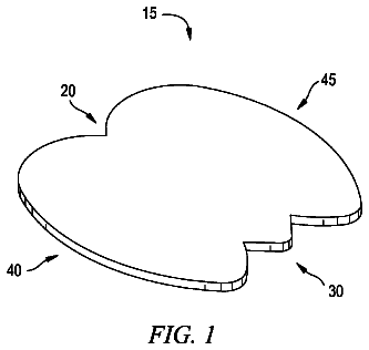
Method of use of a tulip-shaped sacral wound dressing
A sacral wound dressing having a bottom end with three substantially V-shaped projections.
US 8,563,943 B2 · Assignee: Mitsubishi Electric Corporation · Inventors: Iwata; Takaaki et al.
Sheet 1 of 14 from the published document. All sheets in the USPTO PDF
A particle beam irradiation apparatus There is provided a data processing apparatus that displays on a display unit a measured irradiation position value and an irradiation position value error, which is the error of the measured irradiation position relevant value related to the irradiation position of charged particle beam with respect to a desired irradiation position value related to a desired irradiation position, so that the measured irradiation position relevant value and the irradiation position relevant value error correspond to each other. The data processing apparatus displays a desired value display figure indicating a desired irradiation position relevant value at the coordinates of the desired irradiation position value and a measured value display figure at display coordinates, which are coordinates obtained by adding the desired irradiation position value to the coordinates acquired by arithmetically operating an irradiation position value error with deformation coefficients, and displays a line that connects the measured value display figure with the desired value display figure.
A particle beam therapy system is a medical apparatus for performing treatment by irradiating a charged particle beam onto a diseased site such as a cancer. The function, to be required, of a particle beam therapy system is to form an irradiation field in such a way as to provide a diseased site such as a cancer with a dose required for treatment and to provide other normal tissues with as few dose as possible. Irradiation field forming methods include the broad beam irradiation method and the scanning irradiation method. In the broad beam irradiation method, at first, an irradiation field is enlarged by use of a scatterer or the like and then is formed to conform to a diseased site by use of a collimator, a bolus, or the like. Because its safety had been assured through clinical research, the broad beam irradiation method has most widely been adopted in a conventional particle beam ther
1 of 14 drawing sheets so far from the published document, cropped to the drawing. Every sheet is in the USPTO PDF.
What the patent claimed, word for word. All of it is now free to use.
The present invention relates to a particle beam irradiation apparatus and a particle beam therapy system for performing treatment of a cancer or the like by use of a particle beam.
A particle beam therapy system is a medical apparatus for performing treatment by irradiating a charged particle beam onto a diseased site such as a cancer. The function, to be required, of a particle beam therapy system is to form an irradiation field in such a way as to provide a diseased site such as a cancer with a dose required for treatment and to provide other normal tissues with as few dose as possible. Irradiation field forming methods include the broad beam irradiation method and the scanning irradiation method.
In the broad beam irradiation method, at first, an irradiation field is enlarged by use of a scatterer or the like and then is formed to conform to a diseased site by use of a collimator, a bolus, or the like. Because its safety had been assured through clinical research, the broad beam irradiation method has most widely been adopted in a conventional particle beam therapy system. However, because the shape of a diseased site differs depending on a patient, or because even in a single and the same patient, a diseased site shrinks as a treatment proceeds, it is required to create a bolus each time the diseased site shrinks; therefore, there has been desired a more flexible irradiation field forming method. Accordingly, in recent years, there have actively been conducted R&Ds in which the scanning irradiation method is adopted in a particle beam therapy system.
The scanning irradiation method denotes a method in which a pencil-shaped thin charged particle beam is irradiated while being three-dimensionally scanned in such a way as to conform to the shape of a diseased site. The scanning irradiation method in which irradiation and non-irradiation of a pencil-shaped thin charged particle beam are alternatively repeated so that the pencil-shaped thin charged particle beam is irradiated in a spot shape and in a pointillism manner is referred to as the spot scanning method, in particular. The scanning irradiation method in which a pencil-shaped thin charged particle beam is scanned while being irradiated so that the pencil-shaped thin charged particle beam is irradiated in a one-stroke writing manner is referred to as the raster-scanning method, in particular. In each of the spot scanning method and the raster-scanning method, in order to scan a pencil-shaped thin charged particle beam, there is utilized an electromagnet, referred to as a scanning electromagnet or a "so-sa" electromagnet (referred to as a "scanning electromagnet", hereinafter), that makes a magnetic field change at high speed.
It goes without saying that in order to acquire high scanning accuracy of a scanning electromagnet, i.e., high irradiation accuracy of a particle beam therapy system, it is required to appropriately control the scanning electromagnet. However, the irradiation accuracy of a particle beam therapy system is deteriorated with time, even though the particle beam therapy system is adjusted at an initial stage. Accordingly, it is desirable to display the irradiation position accuracy in such a way that the tendency thereof is observed at a glance, so that the irradiation accuracy of the particle beam therapy system can appropriately be maintained and the maintenance thereof can be performed. Patent Document 1 discloses a charged particle beam irradiation system in which based on a detection signal from a position monitor, the deviation (the difference from the desired value) of a beam irradiation position is calculated; it is determined whether or not the calculated deviation of a beam irradiation position has exceeded an allowable value; for example, in the case where it is determined that the deviation of a beam irradiation position has exceeded the allowable value, an interlock signal and a display signal are outputted to an output unit; and then the beam irradiation is stopped.
Patent Document
[Patent Document 1] Japanese Patent Application Laid-Open No. 2009-39219 (Paragraphs 0043 and 0050)
Problems to be Solved by the Invention
The charged particle beam irradiation system disclosed in Patent Document 1 makes it possible that based on a detection signal from a position monitor, the deviation (the difference from the desired value) of a beam irradiation position is calculated; it is determined whether or not the calculated deviation of a beam irradiation position has exceeded an allowable value; then, in the case where it is determined that the deviation of a beam irradiation position has exceeded the allowable value, the beam irradiation is stopped. However, with regard to the foregoing charged particle beam irradiation system, there exists no method of displaying the accuracy of a charged particle beam irradiation position in such a way that the tendency thereof is observed at a glance, and the function therefor is not provided. In particular, in an apparatus of the type in which a beam is irradiated while being scanned, in terms of maintaining the irradiation accuracy and performing the maintenance, extremely important are that the irradiation position and the irradiation position error can be displayed in such a way as to correspond to each other and that the irradiation position relevant value related to the irradiation position and the irradiation position relevant value error can be displayed in such a way as to correspond to each other.
The "irradiation position relevant value related to the irradiation position" does not necessarily denote the irradiation position itself; it is a value that has a one-to-one relationship with the irradiation position and from which the irradiation position can be derived. For example, each of the output value of a position monitor, the output value of a magnetic-field sensor mounted on a scanning electromagnet, and the like corresponds to the irradiation position relevant value related to the irradiation position. Additionally, the irradiation position relevant value error denotes the error in the irradiation position relevant value with respect to a desired irradiation position relevant value. Here, even though the desired irradiation position relevant value does not necessarily denote the desired irradiation position itself, it is a value that has a one-to-one relationship with the desired irradiation position, because the desired irradiation position relevant value and the desired irradiation position are related to each other in the same manner as the irradiation position and the irradiation position relevant value are related to each other, and from which the desired irradiation position can be derived.
The present invention has been implemented for the purpose of solving the foregoing problems; the objective thereof is to provide a particle beam irradiation apparatus in which the irradiation position and the irradiation position error can be displayed in such a way as to correspond to each other or the irradiation position relevant value related to the irradiation position of a charged particle beam and the irradiation position relevant value error can be displayed in such a way as to correspond to each other.
Means for Solving the Problems
There are provided a detector that detects a measured irradiation position relevant value related to the irradiation position of a charged particle beam, and a data processing apparatus that displays on a display unit the measured irradiation position relevant value and an irradiation position relevant value error, which is an error of the measured irradiation position relative value with respect to a desired irradiation position relevant value related to a desired irradiation position of the charged particle beam, in such a way that the measured irradiation position relevant value and the irradiation position relevant value error correspond to each other. The data processing apparatus has an input unit that receives the measured irradiation position relevant value and the desired irradiation position relevant value; and a calculation unit that displays a desired value display figure indicating the desired irradiation position relevant value at the coordinates of the desired irradiation position relevant value and a measured value display figure indicating the measured irradiation position relevant value at display coordinates, which are coordinates obtained by adding the desired irradiation position relevant value to the coordinates acquired by arithmetically operating the irradiation position relevant value error with deformation coefficients, when the desired value display figure and the measured value display figure are displayed in a display region which is the reproduction of an irradiation-region relevant region related to an irradiation region of the charged particle beam, and that displays a line that connects the measured value display figure with the desired value display figure.
There are provided a detector that detects a measured irradiation position relevant value related to the irradiation position of a charged particle beam, and a data processing apparatus that calculates a measured irradiation position of the charged particle beam, based on the measured irradiation position relevant value, and displays on a display unit the measured irradiation position and an irradiation position error, which is the error of the measured irradiation position with respect to a desired irradiation position of the charged particle beam, in such a way that the measured irradiation position and the irradiation position error correspond to each other. The data processing apparatus has an input unit that receives the measured irradiation position relevant value and the desired irradiation position; and a calculation unit that displays a desired value display figure indicating the desired irradiation position at the coordinates of the desired irradiation position and a measured value display figure indicating the measured irradiation position at display coordinates, which are coordinates obtained by adding the desired irradiation position to the coordinates acquired by arithmetically operating the irradiation position error with deformation coefficients, when the desired value display figure and the measured value display figure are displayed in a display region which is the reproduction of an irradiation region of the charged particle beam, and that displays a line that connects the measured value display figure with the desired value display figure.
Advantage of the Invention
In a particle beam irradiation apparatus according to the present invention, the irradiation position accuracy of a charged particle beam can be displayed in such a way that the irradiation position relevant value related to the irradiation position and the irradiation position relevant value error correspond to each other. Moreover, the irradiation position accuracy of a charged particle beam can be displayed in such a way that the irradiation position and the irradiation position error correspond to each other. Therefore, the user can intuitively and easily understand the foregoing display, and can readily grasp the irradiation position accuracy displayed in such a way that the irradiation position relevant value related to the irradiation position of a charged particle beam and the irradiation position relevant value error correspond to each other and the irradiation position accuracy displayed in such a way that the measured irradiation position of the charged particle beam and the irradiation position error correspond to each other. As a result, it is made possible to appropriately maintain the irradiation position accuracy and to perform the maintenance.
FIG. 1 is a schematic block diagram illustrating a particle beam irradiation apparatus according to Embodiment 1 of the present invention;
FIG. 2 is a chart representing a pincushion expression displayed by the data processing apparatus in FIG. 1;
FIG. 3 is a chart representing an irradiation position in contrast to the pincushion expression in FIG. 2;
FIG. 4 is a chart representing a time-series expression of an X-direction error displayed by the data processing apparatus in FIG. 1;
FIG. 5 is a chart representing a time-series expression of a Y-direction error displayed by the data processing apparatus in FIG. 1;
FIG. 6 is a chart representing error vector expression displayed by the data processing apparatus in FIG. 1;
FIG. 7 is a chart representing first pincushion expression according to Embodiment 2 of the present invention;
FIG. 8 is a chart representing second pincushion expression according to Embodiment 2 of the present invention;
FIG. 9 is a schematic block diagram illustrating a particle beam irradiation apparatus according to Embodiment 3 of the present invention;
FIG. 10 is a chart representing a pincushion expression displayed by the data processing apparatus in FIG. 9;
FIG. 11 is a chart representing a time-series expression of an X-direction error displayed by the data processing apparatus in FIG. 9;
FIG. 12 is a chart representing a time-series expression of a Y-direction error displayed by the data processing apparatus in FIG. 9;
FIG. 13 is a chart representing error vector expression displayed by the data processing apparatus in FIG. 9;
FIG. 14 is a chart representing first pincushion expression according to Embodiment 4 of the present invention;
FIG. 15 is a chart representing second pincushion expression according to Embodiment 4 of the present invention;
FIG. 16 is a flowchart for a data display program according to Embodiment 5 of the present invention;
FIG. 17 is a configuration diagram illustrating a particle beam therapy system according to Embodiment 6 of the present invention; and
FIG. 18 is a control block diagram illustrating a particle beam therapy system according to Embodiment 6 of the present invention.
Embodiment 1
FIG. 1 is a schematic configuration diagram illustrating a particle beam irradiation apparatus according to Embodiment 1 of the present invention. A particle beam irradiation apparatus 58 has an irradiation apparatus unit 2 and a control/management unit 3 that controls and manages the irradiation apparatus unit 2. The irradiation apparatus unit 2 is provided with an X-direction scanning electromagnet 10 and a Y-direction scanning electromagnet 11 that scan a charged particle beam 1 in the X direction and the Y direction, respectively, which are directions perpendicular to the charged particle beam 1; an upstream-side position monitor 12a, a dose monitor 13, a downstream-side position monitor 12b, and a scanning electromagnet power source 14. The control/management unit 3 is provided with an irradiation control apparatus 15 that controls the irradiation apparatus unit 2 and a data processing apparatus 19. The traveling direction of the charged particle beam 1 is the Z direction.
The X-direction scanning electromagnet 10 is a scanning electromagnet that performs X-direction scanning with the charged particle beam 1; the Y-direction scanning electromagnet 11 is a scanning electromagnet that performs Y-direction scanning with the charged particle beam 1. The upstream-side position monitor 12a and the downstream-side position monitor 12b detect the beam peak position (passing position), of the beam, through which the charged particle beam 1 that has been scanned by the X-direction scanning electromagnet 10 and the Y-direction scanning electromagnet 11 passes. The dose monitor 13 detects the dose of the charged particle beam 1. The irradiation control apparatus 15 controls the irradiation position of the charged particle beam 1 on an irradiation subject 18, based on treatment plan data created by an unillustrated treatment planning apparatus; when the dose measured by the dose monitor 13 and converted into digital data reaches the desired dose, the charged particle beam 1 is stopped. The scanning electromagnet power source 14 changes setting currents for the X-direction scanning electromagnet 10 and the Y-direction scanning electromagnet 11, based on control inputs (command currents), which are outputted from the irradiation control apparatus 15, to the X-direction scanning electromagnet 10 and the Y-direction scanning electromagnet 11.
The data processing apparatus 19 displays, on a display region an irradiation region related to an irradiation region, the irradiation position (X, Y) of the charged particle beam 1 and an error at the irradiation position (X, Y) in such a way that they correspond to each other; alternatively, the data processing apparatus 19 displays, on a display region which is the reproduction of an irradiation-region relevant region related to the irradiation region, an irradiation position relevant value (A.sub.X, A.sub.Y) related to the irradiation position (X, Y) of the charged particle beam 1 and an error (irradiation position relevant value error (E.sub.X, E.sub.Y)) at the irradiation position relevant value in such a way that they correspond to each other. The irradiation position relevant value (A.sub.X, A.sub.Y)) includes a desired irradiation position relevant value (A0.sub.X, A0.sub.Y) related to a desired irradiation position (X0, Y0) and an measured irradiation position relevant value (A1.sub.X, A1.sub.Y) related to an measured irradiation position (X1, Y1), of the charged particle beam 1, measured by the position monitors 12a and 12b and calculated. The irradiation position relevant value error (E.sub.X, E.sub.Y) is a value obtained by subtracting the desired irradiation position relevant value (A0.sub.X, A0.sub.Y) from the measured irradiation position relevant value (A1.sub.X, A1.sub.Y). The irradiation-region relevant region related to the irradiation region is a position monitor value region obtained by two-dimensionally expressing the output values of the position monitors 12a and 12b. This embodiment will be explained by use of an irradiation region obtained by transforming the position monitor value region of the charged particle beam 1 into the irradiation position (X, Y) on the irradiation subject. The irradiation position, the desired irradiation position, the measured irradiation position, the positional error can paradoxically be expressed as follows: The irradiation position corresponds to information by converting the irradiation position relevant value. The desired irradiation position corresponds to information by converting the desired irradiation position relevant value. The measured irradiation position corresponds to information by converting the measured irradiation position relevant value. The positional error corresponds to information by converting the irradiation position relevant value error. Additionally, the irradiation-region relevant region, the irradiation position relevant value, the desired irradiation position relevant value, the measured irradiation position relevant value, and the irradiation position relevant value error are appropriately expressed with parentheses in such a way as to be attached to the corresponding phrases.
As the data processing apparatus 19, dedicated hardware may be utilized; however, a universal personal computer or a workstation can also be utilized. In this embodiment, for easier understanding, there will be explained a case where a universal personal computer or a workstation is utilized. The data processing apparatus 19 has an input unit 41 to which the desired irradiation position (desired irradiation position relevant value) and the measured irradiation position (measured irradiation position relevant value) in the irradiation region (irradiation-region relevant region) are inputted, a display unit 43 that displays a reproduced irradiation region on a screen, and a calculation unit 42 that performs processing for displaying the reproduced irradiation region on the display unit 43. The data processing apparatus 19 has first through fourth functions; the result realized by these functions is represented in FIG. 2. FIG. 2 is a chart representing pincushion expression displayed by a data processing apparatus according to Embodiment 1 of the present invention. The definition and the like of the pincushion expression will be described later.
The first function of the data processing apparatus 19 is to reproduce and display the irradiation region (irradiation-region relevant region) of the charged particle beam 1 on the display unit screen of the data processing apparatus 19. The first function is implemented by a region display calculation unit in the calculation unit 42. In FIG. 2, the part, drawn by dotted lines in the shape of a lattice, in which graded scales are provided with an abscissa 21 (corresponding to the X direction) and an ordinate 22 (corresponding to the Y direction) corresponds to a display realized by the first function. It is desirable that the origin of pincushion expression 20 (20a) reproduced and displayed on the display unit screen corresponds to an isocenter, which is an irradiation reference. The X direction and the Y direction may be determined in an arbitrary manner in a particle beam therapy system; in general, the X-direction scanning electromagnet and the Y-direction scanning electromagnet are provided in such a way that the respective scanning directions of a beam coincide with the defined X direction and Y direction.
The second function of the data processing apparatus 19 is to display the desired irradiation position (desired irradiation position relevant value) in such a way that the desired irradiation position is superimposed on the irradiation region (irradiation-region relevant region) reproduced on the screen by the first function. The second function is implemented by a desired value calculation unit in the calculation unit 42. In FIG. 2, the plot of a circle that is not painted out, i.e., a circle 23 whose circumference is drawn by a solid line corresponds to a display realized by the second function. Additionally, in FIG. 2, the arrangement position of the circle 23 corresponds to the "desired position (the position that is stung with a pin: a desired value) of a "pin", described later. The circle 23 will be referred to as a desired irradiation position figure (desired value display figure) 23, as may be necessary.
The third function of the data processing apparatus 19 is to display the measured irradiation position (measured irradiation position relevant value) in such a way that the measured irradiation position is superimposed on the irradiation region (irradiation-region relevant region) reproduced on the screen by the first function and the desired irradiation position (desired irradiation position relevant value) superimposed on the irradiation region by the second function. The third function is implemented by a measured value calculation unit in the calculation unit 42. In FIG. 2, the plot of a circle 24 that is painted out corresponds to a display realized by the third function. Additionally, in FIG. 2, the arrangement position of the circle 24 corresponds to the "measured irradiation position (the pinhead: a measured value) of a "pin", described later. The circle 24 will be referred to as a measured irradiation position figure (measured value display figure) 24, as may be necessary. In the present invention, further contrivance is made to display the measured irradiation position (measured irradiation position relevant value). The further contrivance is that as the display of the measured irradiation position, the positional error (irradiation position relevant value error) at the measured irradiation position is deformed (changed by exaggerating or enhancing the characteristics) and displayed. The foregoing contrivance is represented by mathematical expressions.
Letting P.sub.desired denote the desired irradiation position, and P.sub.measured denote the measured irradiation position, the positional error P.sub.error can be given by the equation (1), and the measured irradiation position P.sub.def obtained by deforming the positional error can be given by the equation (2). P.sub.error=P.sub.measured-P.sub.desired
P.sub.def=P.sub.desired+k(P.sub.error)
where k is a deformation coefficient. The desired irradiation position P.sub.desired, the measured irradiation position P.sub.measured, the measured irradiation position P.sub.def obtained by deforming the positional error, and the positional error P.sub.error are all expressed by vectors and indicate the respective coordinates in the irradiation region. The coordinates of the measured irradiation position P.sub.def calculated through the equation
are display coordinates when the measured irradiation position P.sub.def is displayed in a display region which is he reproduction of the irradiation region. With regard to the desired irradiation position relevant value, the measured irradiation position relevant value, the irradiation position relevant value error, and the deformed measured irradiation position relevant value, it is only necessary that they are expressed by PR.sub.desired, PR.sub.measured, PR.sub.error, and PR.sub.def, and in the equations
and (2), P.sub.desired, P.sub.measured, P.sub.error, and P.sub.def are replaces by PR.sub.desired, PR.sub.measured, PR.sub.error, and PR.sub.def, respectively, i.e., by symbols with R. Hereinafter, a symbol with R suggests that it is related to an irradiation position relevant value.
Assuming that the deformation coefficient k is "1", the measured irradiation position P.sub.def is not deformed; the arrangement position of the measured irradiation position figure 24 is displayed at an undeformed real measured irradiation position. Assuming that the deformation coefficient k is "0", the measured irradiation position P.sub.def is given a position corresponding to the desired irradiation position P.sub.desired. In FIG. 2, each of a plurality of measured irradiation position figures 24 represents an example of measured irradiation position P.sub.def when it is assumed that the deformation coefficient k is "30". By plotting the measured irradiation positions P.sub.def without utilizing the deformation coefficient k, FIG. 3 is obtained. FIG. 3 is a chart representing an irradiation position in contrast to the pincushion expression 20 in FIG. 2. The part indicated by a dotted-line circle A in an irradiation position display 35 is an enlargement subject part, and the part represented by a dotted-line circle B is an enlarged enlargement subject part. The dotted-line circle 33 is a desired irradiation position figure and corresponds to the desired irradiation position figure 23 in FIG. 2. The desired irradiation position figure is represented by a dotted line so as to be distinguished from the measured irradiation position figure 24. The irradiation position error is small compared to the area of a display region which is the reproduction of the irradiation region in the irradiation position display 35; therefore, in general, without deforming the irradiation position error, it is difficult to determine the tendency thereof, as in FIG. 3.
The fourth function of the data processing apparatus 19 is to display the desired irradiation position P.sub.desired (desired irradiation position relevant value PR.sub.desired), displayed by the second function, and the measured irradiation position P.sub.def (measured irradiation position relevant value PR.sub.def), obtained by deforming the positional error P.sub.error (irradiation position relevant value error PR.sub.error) displayed by the third function, that are connected with each other with a line. The fourth function is implemented by a line display calculation unit in the calculation unit 42. In FIG. 2, a line 25 corresponds to the expression realized by the fourth function. Additionally, the line 25 corresponds to the "pin body" of a "pin", described later. In the case where there exists the positional error P.sub.error, the measured irradiation position P.sub.def obtained by deforming the positional error P.sub.error leaves rapidly the desired irradiation position P.sub.desired, as the deformation coefficient k increases in the third function. Accordingly, the fourth function displays the desired irradiation position figure 23 indicating the desired irradiation position and the measured irradiation position figure 24 indicating the measured irradiation position that are connected with each other with the line 25, so that the relationship between then can easily be understood. It can be said that the third and fourth functions are special technical features in the present invention.
Here, the pin and the pincushion expression will be explained. In FIG. 2, the combination of the circle 24 that is painted out and the line 25 looks as if it were a pin (marking pin). The expression, represented in FIG. 2, on the display unit screen of the data processing apparatus 19 looks as if a pincushion are stung with pins; therefore, this expression is referred to as "pincushion expression" herein. Additionally, in contrast to the state where a pincushion is stung with pins, the desired irradiation position figure 23 in the pincushion expression 20, the measured irradiation position figure 24 (including both undeformed and deformed figures), and the line 25 that connects the desired irradiation position figure 23 with the measured irradiation position figure 24 correspond to a "position that is stung with a pin", a "pinhead", and a "pin body".
Because the particle beam irradiation apparatus 58 according to Embodiment 1 is provided with the data processing apparatus 19 having the four functions, the irradiation position accuracy of the charged particle beam 1 can be displayed in such a way that the irradiation position P and the irradiation position error P.sub.error correspond to each other. Additionally, the irradiation position accuracy of the charged particle beam 1 can be displayed in such a way that the irradiation position relevant value PR related to the irradiation position and the irradiation position relevant value error PR.sub.error correspond to each other. Therefore, the user can intuitively and easily understand the foregoing display, and can readily grasp the irradiation position accuracy displayed in such a way that the irradiation position P of the charged particle beam 1 and the irradiation position error P.sub.error correspond to each other and the irradiation position accuracy displayed in such a way that the irradiation position relevant value PR related to the irradiation position of the charged particle beam 1 and the irradiation position relevant value error PR.sub.error correspond to each other. As a result, it is made possible to appropriately maintain the irradiation position accuracy and to perform the maintenance.
It may be allowed that on the display unit screen of the data processing apparatus 19, another display for supplementing the pincushion expression 20 is implemented. FIGS. 4 and 5 are graphs (referred to as "time-series expression", hereinafter) representing in a time-series manner the X-direction component and the Y-direction component, respectively, of the positional error. FIG. 4 is a graph representing the time-series expression 30 (30a) of the X-direction error; FIG. 5 is a graph representing the time-series expression 30 (30b) of the Y-direction error. The abscissa denotes the irradiation number indicating the order of irradiation of the charged particle beam 1; the ordinate denotes the error in the position (irradiation position relevant value). Data with larger irradiation number is more advanced in time than data with smaller irradiation number. Thus, the time-series expression (30a, 30b) gives effective information in the case where the positional error (irradiation position relevant value error) is analyzed in relation to the time. For example, there can readily be grasped information such as that the error has become large after the irradiation number "n" (the time tn).
In addition, it may be allowed that on the display unit screen of the data processing apparatus 19, another display for supplementing the pincushion expression 20 is implemented. FIG. 6 is a chart representing the vector expression of errors in the positions (irradiation position relevant values). Hereinafter, a chart in which errors are expressed in a vector manner will be referred to as "error vector expression", and a chart in which errors in the positions are expressed in a vector manner will be referred to as "positional error (irradiation position relevant value error) vector expression". The abscissa denotes the X-direction error; the ordinate denotes the Y-direction error. In an error vector expression 31, an error point 32 is displayed corresponding to the irradiation spot of the charged particle beam 1. Among the error vector expressions 31, which are expressions on such an error plane as in FIG. 6, the error vector expression 31 of a positional error is distinguished as a positional error vector expression 31a. The error vector expression 31 is the most effective expression method in the case where it is determined whether or not actual irradiation is being implemented within the allowable error range of the particle beam irradiation apparatus 58. In the error vector expression 31, by further displaying a border line indicating the boundary of the allowable error range, it can readily be determined whether or not actual irradiation has been implemented within the allowable error range.
Measured irradiation position relative data, which is data for creating the pincushion expression 20, the time-series expression 30, and the error vector expression 31, is obtained not only during irradiation of the charged particle beam 1 but also during particle-beam therapy. The measured irradiation position relative data is data related to the measured irradiation position of the charged particle beam 1. In Embodiment 1, the measured irradiation position relative data is the data on the position, of the charged particle beam 1, detected and calculated by the position monitors 12a and 12b. The measured irradiation position relative data may be the data on the magnetic field, of the charged particle beam 1, detected by magnetic-field sensors 8 and 9 (refer to FIG. 9).
Additionally, the measured irradiation position relative data may not be the position data of the charged particle beam 1 that has passed through the position monitor 12a or 12b, but be the position data of the charged particle beam 1 on a given reference plane. For example, it may be allowed that as the reference plane, there is adopted a slicing plane obtained by slicing the irradiation subject 18, and that as measured irradiation position relative data, there is adopted the position data of the charged particle beam 1 on the slicing plane.
The pincushion expression 20, the time-series expression 30, and the error vector expression 31 can be displayed not only during irradiation (online display) but also at an arbitrary time after irradiation (offline display). In the case where there is limited the capacity of a memory for storing the measured irradiation position relative data, the data may be obtained, for example, at the time of a specific event such as calibration conducted first thing in the morning of a day when the particle beam irradiation apparatus 58 is operated or the first therapy of the day. Even in the case where an error is produces in the measurement data, an allowable range exists for the error; therefore, even in the case where the data is obtained at the time of a specific event, there can be determined the timing when the maintenance is implemented.
The pincushion expression 20, the time-series expression 30, and the error vector expression 31 can be utilized also in setting and calibrating the particle beam irradiation apparatus 58. In particular, the online display is effective. Also in this case, the irradiation position accuracy of the charged particle beam 1 can be displayed in such a way that the irradiation position P and the irradiation position error P.sub.error correspond to each other. Additionally, the irradiation position accuracy of the charged particle beam 1 can be displayed in such a way that the irradiation position relevant value PR related to the irradiation position and the irradiation position relevant value error PR.sub.error correspond to each other. Accordingly, there can readily be made consideration about the plan of adjustment in performing setting, i.e., as to in which direction (the X direction or the Y direction) and how much correction is implemented.
In the offline display, for example, three-day data pieces are displayed in a superimposed manner, whereby a change in the error can be viewed. By superimposing and displaying data on the reference day, the difference with respect to the reference day can be viewed. It is made possible to determine the maintenance timing through viewing the change in the error or the difference with respect to the reference day.
The input value to the deformation coefficient k is selected for each apparatus. In general, the error is proportional to the size of the electromagnet. Additionally, the error is proportional to the distance between the electromagnet and the irradiation subject. In the case where the difference between the measured irradiation position P.sub.measured (measured irradiation position relevant value PR.sub.measured) and the desired irradiation position P.sub.desired (desired irradiation position relevant value PR.sub.desired) can clearly be seen, the deformation may not be implemented, i.e., the deformation coefficient k may be set to "1". In the case where the error is extremely small, by setting the deformation coefficient k to a large value, the irradiation position accuracy can readily be grasped. Additionally, the default value of the deformation coefficient may be set to a value that has been utilized last time or "1". By utilizing the default value, it is made possible that pincushion expression can be implemented without inputting the deformation coefficient from outside.
The description continues in the full USPTO document.
About 5,850 words. The USPTO PDF has it with every drawing.
Fees are due 3.5, 7.5 and 11.5 years after grant. This patent expired on October 22, 2025, so the fee marked "not paid" was the one that went unpaid.
PARTICLE BEAM IRRADIATION APPARATUS, PARTICLE BEAM THERAPY SYSTEM, AND DATA DISPLAY PROGRAM
Filed Dec 2010 · published Jun 2012Particle beam irradiation apparatus, particle beam therapy system, and data display program
Filed Dec 2010 · granted Oct 2013Earlier publications, parents and continuations. None of them can still be enforced, or this patent would not be listed.
Prior art cited by the examiner or applicant. Useful when you check your own idea for novelty.
Everything on this page comes from the documents linked above.


