 Lapsed, fee not paid9 drawings
Industrial Equipment · US 8,561,881 B2
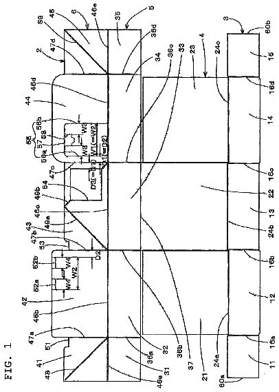
Developed object for building packing box and the packing box
There is provided a packing box having a taking-out opening which can be opened with ease with only one hand.
US 8,561,897 B2 · Assignee: Sky-Trax, Inc. · Inventors: Kunzig; Robert S. et al.
Sheet 1 of 60 from the published document. All sheets in the USPTO PDF
Methods and apparatus for determining the location of one or more unit loads in a coordinate space in a facility, comprising an integrated system that identifies a load by reading indicia on the load, determines the position of the indicia in the coordinate space, and stores the indicia position and load identity in a Label Map. A mobile subsystem on each conveying vehicle identifies the location and orientation of that vehicle using a position/orientation sensor, determines the identity of the load, establishes a Target Cube to discriminate the desired load from nearby loads, confirms acquisition of the load, and communicates the information to a fixed-base subsystem. Load identity and the location and orientation of the vehicle when a load is deposited are used to create a Load Map that contains the identity, position and orientation of all identified loads in the coordinate space.
Tracking the identity and location of physical assets, such as raw materials, semi-finished products and finished products, as they move through the supply chain is operationally imperative in many businesses. "Assets" may include a very wide range of objects conveyed by utility vehicles, including, but not limited to palletized materials such as groups of cartons, single items such as household appliances, or unitized bulk products such as chemical totes. As used in the present invention, a load or "unit load" is a single unit of assets, such as freight or an assembly of goods on a transport structure (e.g., pallet, tote, rack, etc.) that facilitates handling, moving, storing and stacking the materials as a single entity. Unit loads typically combine individual items into a single unit that can be moved easily with an industrial utility vehicle such as a pallet jack or forklift truck. I
1 of 60 drawing sheets so far from the published document, cropped to the drawing. Every sheet is in the USPTO PDF.
What the patent claimed, word for word. All of it is now free to use.
A method and apparatus for determining the location of one or more unit loads of freight in a coordinate space in a facility by reading identifying indicia to identify items, spatially discriminating the items from nearby ones, determining the position and orientation of items by determining the position and orientation of the conveying vehicles such as forklift trucks, and the position of the indicia relative to the conveying vehicle. The identity, location, and orientation of items are stored in a database in a computer memory that can be accessed by all conveying vehicles in the facility; thereby eliminating the necessity of rereading the identifying indicia each time an item is to be located for conveyance. Items may therefore be identified, located and tracked in "real" space of the facility and/or in "virtual" space of computer memory.
Tracking the identity and location of physical assets, such as raw materials, semi-finished products and finished products, as they move through the supply chain is operationally imperative in many businesses. "Assets" may include a very wide range of objects conveyed by utility vehicles, including, but not limited to palletized materials such as groups of cartons, single items such as household appliances, or unitized bulk products such as chemical totes. As used in the present invention, a load or "unit load" is a single unit of assets, such as freight or an assembly of goods on a transport structure (e.g., pallet, tote, rack, etc.) that facilitates handling, moving, storing and stacking the materials as a single entity. Unit loads typically combine individual items into a single unit that can be moved easily with an industrial utility vehicle such as a pallet jack or forklift truck.
In material handling facilities such as factories, warehouses, and distribution centers, asset tracking is the primary task of a wide variety of systems, including inventory control systems, product tracking systems, and warehouse management systems, collectively termed "host systems". The ability to automatically determine and record the identity, position, elevation, and rotational orientation of assets and/or unit loads within a defined coordinate space, without human interaction, is a practical problem that has seen many imperfect solutions.
A variety of technologies have been applied to solve the problem of identifying an asset or unit load. For example, barcode labels, hang tags, ink jet spray markings, and radio frequency tags have been attached to assets and/or unit loads to allow machine readability or manual identification by a human operator. The most common method used today utilizes barcode indicia (typically printed on a label attached to an asset), which are read by hand-held devices, commonly known as barcode scanners or label readers. Data from the hand held device is typically forwarded to a host system such as those mentioned above. As used herein, the term "label reader" refers to any device that reads barcode indicia.
Determining asset or unit load location has been an equally challenging problem, especially in facilities where goods move quickly from point to point, or where human interaction is relied upon to determine the asset's or unit load's location or storage position. Barcode labels have found utility by being attached to storage locations. For example, a warehouse may have rack storage positions, where each position is marked with a barcode label. The operator scans the rack label barcode when an asset or a load is deposited or removed, and that data, along with the asset or unit load identity data, is uploaded to the host.
As with load identification, load location has been determined manually or by machine with a variety of technologies. RFID tags, barcode labels and human readable labels constitute the vast majority of location marking methods, especially for facilities utilizing rack storage. Racks provide physical separation of storage items as well as convenient placement for identifying labels.
In the case of bulk storage, where items are stored in open floor areas, items may be placed in any orientation with little physical separation. Floor markings--typically painted stripes--are the conventional method of indicating storage locations (e.g., see FIG. 18) and separating one location from another. Human readable markings and/or bar code symbols may identify each location in order to allow human reading and/or machine reading, and these may be floor-mounted or suspended above storage locations.
Tracking the movement of assets in a storage facility presents a number of additional problems. Most warehouse and distribution centers employ drivers operating pallet jacks or forklift trucks, and in most of these operations the driver is responsible for collecting inventory data as assets are moved to and from storage locations. Generally drivers use a hand-held barcode scanner to scan a barcode label on the load and to scan a separate barcode label affixed to the floor, hung from above, or attached to a rack face. The act of manually collecting the load tracking data creates several problems including, for example: 1) Driver and vehicle productivity are reduced. The label-reading task takes time away from the driver's primary task of moving the materials. 2) Data errors can occur. The driver may scan the wrong label, or forget to scan. These data errors can result in lost inventory, inefficient operations, and operational disruptions. 3) Driver safety is threatened. Forklift drivers work in a dangerous environment. The scanning operation frequently requires the driver to lean outside the protective driver cage or to dismount and remount the vehicle. The driver is exposed to potential injury when dismounted or leaning outside the protective cage.
In addition to the difficulties introduced by the manual data collection task, an overriding concern is that item identification tags, labels, or other markings can be degraded during shipping and storage, and may become unusable. For example, paper labels with machine-readable barcode identifiers can be torn or defaced, rendering the barcode unreadable. Printing can become wet and smeared, text can be misinterpreted, and labels can be torn off, rendering an item unidentifiable.
Numerous outdoor asset tracking methods and systems have been developed to track outdoor assets such as railroad cars, ships, overland trucks, and freight containers. Most tracking systems utilize the Global Positioning System (GPS) for position determination. GPS is available world-wide and requires no licensing or usage fees. The GPS system is based on radio signals, transmitted from earth orbiting satellites, which can be received at most outdoor locations. For indoor navigation, however, GPS signals can be attenuated, reflected, blocked, or absorbed by building structure or contents, rendering GPS unreliable for indoor use.
Radio technologies have been used to determine the position of objects indoors. While overcoming the radio wave limitations of GPS, other shortcomings have been introduced. For example, object orientation is difficult to determine using radio waves. A number of radio-based systems have been developed using spread spectrum RF technology, signal intensity triangulation, and Radio Frequency Identification (RFID) transponders, but all such systems are subject to radio wave propagation issues and lack orientation sensing. Typical of such RF technology is U.S. Pat. No. 7,957,833, issued to Beucher et al.
For example, U.S. Pat. No. 7,511,662 claims a system and method for providing location determination in a configured environment in which Global Navigation Satellite System Signals may not be available. Local beacon systems generate spread spectrum code division multiple access signals that are received by spectral compression units. That system has utility in applications in which GPS signals are unavailable or limited, for example, in warehouse inventory management, in search and rescue operations and in asset tracking in indoor environments. An important shortcoming of the technology is that object orientation cannot be determined if an object is stationary.
Ultrasonic methods can work well in unobstructed indoor areas, although sound waves are subject to reflections and attenuation problems much like radio waves. For example, U.S. Pat. No. 7,764,574 claims a positioning system that includes ultrasonic satellites and a mobile receiver that receives ultrasonic signals from the satellites to recognize its current position. Similar to the GPS system in architecture, it lacks accurate orientation determination.
Optical methods have been used to track objects indoors with considerable success. For example, determining the location of moveable assets by first determining the location of the conveying vehicles may be accomplished by employing vehicle position determining systems. Such systems are available from a variety of commercial vendors including Sick AG of Waldkirch, Germany, and Kollmorgen Electro-Optical of Northampton, Mass. Laser positioning equipment may be attached to conveying vehicles to provide accurate vehicle position and heading information. These systems employ lasers that scan targets to calculate vehicle position and orientation (heading). System accuracy is suitable for tracking assets such as forklift trucks or guiding automated vehicles indoors. Using this type of system in a bulk storage facility where goods may be stacked on the floor has presented a limitation for laser scanning systems, which rely on the targets to be placed horizontally about the building in order to be visible to the sensor. Items stacked on the floor that rise above the laser's horizontal scan line can obstruct the laser beam, resulting in navigation system failure.
Rotational orientation determination, which is not present in many position determination methods, becomes especially important in applications such as vehicle tracking, vehicle guidance, and asset tracking. Considering materials handling applications, for example, assets may be stored in chosen orientations, with carton labels aligned in a particular direction or pallet openings aligned to facilitate lift truck access from a known direction. Since items in bulk storage may be placed in any orientation, it is important that orientation can be determined in addition to location. One method of determining asset location and orientation is to determine the position and orientation of the conveying vehicle as it acquires or deposits assets. Physical proximity between the asset and the vehicle is assured by the vehicle's mechanical equipment; for example, as a forklift truck picks up a palletized unit load of assets with a load handling mechanism.
Since goods may be stored in three dimensional spaces with items stacked upon one another, or stored on racks at elevations above the floor, a position and orientation determination system designed to track assets indoors must provide position information in three dimensions and orientation. The close proximity of many items also creates the problem of discriminating from them only those items intended for the current load. The combination of position determination, elevation determination and angular orientation determination and the ability to discriminate an item from nearby items is therefore desired.
A position and rotation determination method and apparatus is taught in U.S. patent application Ser. No. 11/292,463, now U.S. Pat. No. 7,845,560, titled Method and Apparatus for Determining Position and Rotational Orientation of an Object, which is incorporated herein by reference in its entirety. An improved position and rotation determination method is taught in U.S. patent application Ser. No. 12/807,325, titled Method and Apparatus for Managing and Controlling Manned and Automated Utility Vehicles, which is incorporated herein by reference in its entirety. The methods of these patent applications are useful for determining the position and orientation of a conveying vehicle in carrying out the present invention. Other navigation methods as embodied in model NAV 200 available from Sick AG of Reute, Germany, and model NDC8 available from Kollmorgen of Radford, Va. may also be used for determining the position and orientation of a conveying vehicle.
U.S. patent application Ser. No. 12/319,825, titled Optical Position Marker Apparatus, Mahan, et al., filed Jan. 13, 2009, describes an apparatus for marking predetermined known overhead positional locations within a coordinate space, for viewing by an image acquisition system which determines position and orientation, which is incorporated herein by reference in its entirety.
U.S. patent application Ser. No. 12/321,836, titled Apparatus and Method for Asset Tracking, describes an apparatus and method for tracking the location of one or more assets, comprising an integrated system that identifies an asset, determines the time the asset is acquired by a conveying vehicle, determines the position, elevation and orientation of the asset at the moment it is acquired, determines the time the asset is deposited by the conveying vehicle, and determines the position, elevation and orientation of the asset at the time the asset is deposited, each position, elevation and orientation being relative to a reference plane. U.S. patent application Ser. No. 12/321,836 is incorporated herein by reference in its entirety.
The prior art does not address the issue of identifying a specific asset, or unit load to be acquired by a conveying vehicle, as the vehicle approaches a group of similar loads in close proximity to each other. The prior art also does not address the issue of identifying a load if its identifying indicia is missing, unreadable or not in view when the conveying vehicle approaches the load.
The present invention addresses many of the above problems. A novel method is disclosed of identifying and discriminating assets by searching a "virtual space" created from databases. An asset needs be identified only one time as it moves into, through, and out of a facility such as a warehouse. Each time the asset is moved the asset can be positively identified by any conveying vehicle, from any angle of approach, anywhere within the three-dimensional coordinate space, without "real space" identification. After an asset is first identified and located, the identifying markings such as tags, labels, printing, etc. are no longer needed for that item to be accurately tracked.
In a first aspect, embodiments of the present invention disclose methods and systems for identifying and locating items within a facility and create a database comprising a Label Map; in a second aspect, embodiments of the present invention create a virtual space in computer memory termed a Targeting Lane to discriminate adjacent items; in a third aspect, embodiments of the present invention track the identity, location, and movement of multiple assets; and in a fourth aspect, embodiments of the present invention track the identity, location and movement of assets that are inadvertently displaced from their known storage location.
According to one aspect, embodiments of the present invention build a database termed a "Label Map" of the three-dimensional locations and identities of identifying labels, and use the labels' identity and the position and orientation of a conveying vehicle to build a database termed a "Load Map" of asset identities and locations. In a first aspect, the present invention presents a method for identifying and locating items with one or more optical label readers, each label reader being mounted on a corresponding conveying vehicle at a known position and orientation relative to a center and a directional axis of the vehicle, each conveying vehicle having an optical image acquisition system mounted thereon for sensing position and rotational orientation within a facility having an array of position markers, each asset having a machine-readable encoded indicia of a predetermined size thereon.
In one embodiment, the method comprises the steps of:
a) repeatedly determining the position of the center of the vehicle and the rotational orientation of the directional axis of the vehicle;
b) acquiring images with the one or more label readers as each conveying vehicle moves about the facility;
c) processing each image to determine if that image contains a label having readable indicia;
d) if the indicia is not readable, repeating steps b) and c);
e) if the indicia is readable: 1) decoding the indicia to identify the asset; 2) determining a center of the indicia on the label; and 3) determining a location of the label center relative to the label reader based upon the position and the size of the indicia within the image;
f) determining the position of the label within the facility using the location of the indicia relative to the label reader, the position and rotational orientation of the label reader relative to the center of the vehicle and the directional axis of the vehicle and the position of the center of the vehicle and directional axis of the vehicle within the facility; and
g) storing the identity and the position of each readable label within the facility in a database, called a Label Map, in a memory in a computer.
The Label Map or Load Map enables a mobile subsystem onboard the conveying vehicle to interrogate computer memory (i.e., "look" into virtual space) and discriminate among multiple assets, only those that should be included within the Load On Board and identify assets even when an identifying label is not detectable by the label reader sensor. The Load Map facilitates an asset being identified and transported without the need for a label reader sensor or the presence of a readable identifying label.
In a second aspect the present invention creates a virtual space termed a Targeting Lane, existing only in computer memory, which is defined in coordinates that lie in front of the conveying vehicle's load handling mechanism. The Targeting Lane is used to discriminate between closely stacked or spaced assets, enabling the conveying vehicle to identify a potential, i.e., "target", load, when multiple labels are within the field of view of the label reader sensor, or when multiple assets are present within the Targeting Lane. In one embodiment, the Targeting Lane is used in a method of transporting an asset in a facility from a first location to a second location, comprises the steps of:
a) creating a Global Label Map database;
b) identifying the asset to be transported and transmitting that identity to a conveying vehicle;
c) determining the position of the asset from a copy of the Global Label Map in the memory of the mobile computer;
d) defining a Targeting Lane in front of the load handling (lift) mechanism of the conveying vehicle and determining if any labels are in the Targeting Lane;
e) if no labels are in the Targeting Lane, repeating steps c) and d);
f) if any labels are in the Targeting Lane, 1) determining the closest label in Targeting Lane; 2) projecting a Target Cube depth from the closest label position;
g) checking label positions in the Label Map to determine if any labels are within the Target Cube;
h) If any labels are in the Target Cube, determining if the load detecting device has detected a "Load ON" event;
i) if a "Load ON" event has not occurred, repeating steps d-g;
j) if a "Load ON" event has occurred, then determining label(s) and their associated item(s) to be part of a "Load On Board" or "Current Load";
k) acquiring the asset(s);
l) transporting the asset(s) to a second position and orientation;
m) depositing the asset(s) at the second location;
n) determining the position and the orientation of the asset(s) within the facility when the load detecting device detects the item has been deposited ("Load Off") by using the size of the load, the location of the load relative to the conveying vehicle and the position of the center of the vehicle and orientation of the directional axis of the vehicle;
o) storing the identity, the position and the orientation of the deposited asset(s) in the Local Load Map in the memory in the mobile computer.
p) transmitting the identity, the position and the orientation of the deposited asset(s) to the system controller over the wireless network; and
q) storing the identity, the position and the orientation of the deposited asset(s) in the Global Load Map.
In a third aspect, the present invention tracks multiple assets being conveyed on board a single conveying vehicle by spatially discriminating the asset labels and determining their position relative to the vehicle.
In a fourth aspect, the present invention tracks the movement of assets that are displaced from their stored position when the conveying vehicle pushes the stored asset while depositing another asset in the stored asset's original position.
In one embodiment, the method of tracking the identity and location and rotational orientation of a second load displaced during the deposition of a first load being transported by a conveying vehicle, comprises the steps of:
a) identifying a desired storage location for a first load being transported;
b) determining that a second load occupies the desired storage location;
c) contacting the second load with the first load and determining the location and direction of travel of the conveying vehicle at contact;
d) pushing the second load to a displaced location when the first load is being deposited in the desired storage location;
e) upon deposition of the first load, when a Load Off event occurs, updating the locations and rotational orientations of the second load and the first load in the Local Label Map and Local Load Map, the distance of displacement of the second load being determined by the size of the first load and the direction of the displacement being determined by the direction of travel of the conveying vehicle at contact.
One apparatus for carrying out the methods comprises an integrated system comprising a fixed-base subsystem, called a controller, and one or more mobile subsystems. The controller comprises a computer having a computational unit, a data storage unit, a communications network interface, an operator interface, a wireless local area network interface and a base station wireless local area network communication unit, connected to the computer, for communicating with one or more mobile communication units.
The mobile subsystems, each mounted onboard a conveying vehicle, each comprise a mobile computer device having a computational unit and a data storage unit; a sensor network interface for communicating with a plurality of onboard devices, a wireless local area network interface, a vehicle driver interface, and a plurality of onboard devices. The plurality of onboard devices includes a position/orientation sensor unit to determine the location in two dimensions, and the rotational orientation of the conveying vehicle in a facility coordinate system; a label reader sensor device for detecting and identifying a label having a machine-readable symbol on a load and decoding the machine-readable symbol; a load detection device, indicating the presence or absence of a load on a lifting mechanism of the conveying vehicle; a lift height detection device for determining the elevation of the lifting mechanism on the conveying vehicle relative to the reference plane; and a wireless local area network communication unit for communicating with the base station wireless communication unit.
Additional types of conveying vehicles are accommodated by the present invention. For example, scissor trucks, turret trucks, order picker trucks are accommodated by the addition of sensors on the conveying vehicle that measure the position and rotational orientation of the forks relative to the position and rotational orientation of the conveying vehicle. The scissor truck would have a scissor extension sensor to measure the distance of the fork assembly from the conveying vehicle. The turret truck would have a lateral displacement sensor to measure the lateral displacement of the fork assembly and a fork rotation sensor to measure the rotational position of the fork assembly.
In operation, an exemplary load tracking system operates as follows. As the conveying vehicles travel throughout a facility, the label reader sensors of the mobile subsystems continuously acquire images of load labels and the position (or location) sensors simultaneously track the position and rotational orientation of each conveying vehicle. The identity of each load label is decoded from the label image and the position of each label is calculated from the image data (label size and position of the label within each image) and the known position of the vehicle at the time the label is decoded. The mobile subsystem on each vehicle thus builds a database of labels it has seen. This database is termed a Local Label Map.
Using known size characteristics of loads based on the average (or nominal) size load for a given facility, and/or the known positions of the labels on each load based on the standardized placement of labels, the position (or location) of the center of each load and the rotational orientation of each load is accumulated in a database known as a Local Load Map. When a conveying vehicle handles a load and deposits it at a destination location the Load Map is updated to reflect the current location and orientation of the load.
Each mobile subsystem transmits data from the Local Label Map and the Local Load Map to the controller (fixed-base subsystem). By accumulating the Label Map and the Load Map information from each mobile subsystem the controller builds a Global Label Map of label identities, and, and a Global Load Map of all load identities, positions (locations), and orientations. This Global Load Map can then be shared with all mobile subsystems for subsequent location and acquisition of individual loads.
When a conveying vehicle is dispatched to a particular load, the conveying vehicle approaches the load and a "Targeting Lane" is created by the mobile computer device. This Targeting Lane is defined in memory as though it were being projected in front of the conveying vehicle's load handling mechanism. It is defined as a rectangular cuboid, having eight
corners where each corner is a point in space, and six
surfaces (planes), where each surface and corner point are calculated repeatedly as the conveying vehicle moves. When one or more labels have been identified by the mobile subsystem a "Target Cube" is created (defined in memory) using the position of the label to define the face of the cube nearest the conveying vehicle. The size of the Target Cube is determined by the expected (average or nominal) size of the load. The Target Cube discriminates labels outside of the Target Cube so that they are not considered part of the load to be acquired. At the time the load is acquired by the conveying vehicle, the load detection device generates a "Load ON" signal. The position and orientation of the load is calculated based upon the position and orientation of the conveying vehicle and the position and orientation of the load handling mechanism. The elevation of the load is determined by the lift height detection device. The position, elevation and orientation of the load at the moment it is acquired may be stored in the Local Load Map. When the load is deposited by the conveying vehicle, the load detection device generates a "Load OFF" signal. The position, elevation and orientation of the load are determined and the information is stored in the Local Load Map. When the load has been deposited, the mobile subsystem transmits the Local Load Map information about the load to the fixed-base subsystem which in turn updates the Global Load Map.
As the conveying vehicle approaches potential loads, the desired load is detected and identified by the mobile subsystem on the conveying vehicle by projecting the appropriate Targeting Lane into the Local Label Map or the Local Load Map and including only those loads that are within the Target Cube. The load is then acquired by the conveying vehicle, the load detection device confirming the presence of the load on the conveying vehicle. The lift height detection device determines the elevation of the load relative to the reference plane at the origin location. The conveying vehicle delivers the load to a destination location, the position/orientation sensor unit determines the location and the rotational orientation of the conveying vehicle, and the lift height detection device determines the elevation of the load relative to the reference plane at the destination location. The mobile communication unit communicates to the fixed-base subsystem the identity of the load, the time of acquisition and delivery, and the location, elevation and rotational orientation of the load at the destination location.
In a preferred embodiment, the system determines the instantaneous location of each load using the systems and methods disclosed in one or more of U.S. Pat. No. 7,845,560; U.S. patent application Ser. No. 12/319,825; U.S. patent application Ser. No. 12/321,836; and U.S. patent application Ser. No. 12/807,325, the details of which are incorporated herein by reference in their entirety. An array of uniquely encoded position markers distributed throughout the operational space in such a manner that at least one marker is within view of an image acquisition system mounted on a conveying vehicle. Images of the at least one marker are acquired and decoded, and the position and rotational orientation of the conveying vehicle are calculated. Sensors on the conveying vehicle enable the system to determine the precise location, including elevation relative to a reference plane, of the load (such as an object on a pallet) being transported by the conveying vehicle.
Communication between the fixed-base host computer and the mobile subsystems mounted on the conveying vehicles may use any wireless communication protocol authorized for use in a particular country of use.
The system described above removes operator involvement from the data collection task and improves operational efficiency as well as operator safety as loads are moved through a facility.
Additional features and advantages of the invention will be made apparent from the following detailed description of illustrative embodiments that proceeds with reference to the accompanying drawings.
The foregoing and other aspects of the present invention are best understood from the following detailed description when read in connection with the accompanying drawings. For the purpose of illustrating the invention, there is shown in the drawings embodiments that are presently preferred, it being understood, however, that the invention is not limited to the specific instrumentalities disclosed. Included in the drawings are the following Figures:
FIG. 1 shows a stylized pictorial three-dimensional view of a materials handling facility;
FIG. 2 shows a detailed view of a conveying vehicle, e.g., a counterbalanced forklift truck and a load;
FIG. 2A shows an exemplary "Reach Truck" having fork extension scissors, with the scissors in the withdrawn, i.e., retracted, position;
FIG. 2B shows a Reach Truck with the scissors in the extended position;
FIG. 2C shows an exemplary "man-up order picker" conveying vehicle with the operator lifted above the floor;
FIG. 3 shows a block diagram showing exemplary interconnection of components on the conveying vehicle;
FIG. 4 is a plan view to show X and Y offsets of a position/orientation sensor camera from the center of the conveying vehicle;
FIG. 4A is a plan view, corresponding to FIG. 2A, that shows X and Y offsets of a position/orientation sensor from the center of a reach truck conveying vehicle with the load handling mechanism withdrawn;
FIG. 4B is a plan view, corresponding to FIG. 2B, that shows X and Y offsets of a position/orientation sensor from the center of a reach truck conveying vehicle with the load handling mechanism extended;
FIG. 4C is a plan view to show X and Y offsets of a position/orientation sensor from the center of a "turret truck" conveying vehicle with the load handling mechanism centered and rotated left;
FIG. 4D is a plan view to show X and Y offsets of a position/orientation sensor from the center of a "turret truck" conveying vehicle with the load handling mechanism translated left and rotated left;
FIG. 4E is a plan view to show X and Y offsets of a position/orientation sensor from the center of a "turret truck" conveying vehicle with the load handling mechanism translated right and rotated right;
FIG. 5 is a plan view showing four possible orientations of a position/orientation sensor camera on the conveying vehicle;
FIG. 6 is a plan view of two Label Readers showing horizontal X and Y offsets from the center of the conveying vehicle;
FIG. 7 is a perspective view of a conveying vehicle showing vertical Z offsets of two Label Readers relative to the Load Datum Point;
FIG. 8 depicts the coordinate axes of the vehicle and the pitch, roll and yaw axes of a Label Reader sensor;
FIG. 9A depicts a typical item label with a two-dimensional barcode;
FIG. 9B depicts a two-dimensional barcode useful for a load identification label;
FIG. 9C depicts an item label or load label having a one-dimensional barcode;
FIG. 9D depicts a one-dimensional barcode useful for a load identification label;
FIG. 9E depicts an alternative one-dimensional barcode useful for a load identification label;
FIG. 10 is a depiction of a typical label used for load identification;
FIG. 11 shows a manned conveying vehicle approaching a stack of unit loads and Targeting Lane projected from the front of the conveying vehicle and shows details of the Targeting Lane;
FIG. 12 shows a manned conveying vehicle approaching a stack of unit loads where some of the unit loads lie within the Targeting Lane;
FIG. 13 shows the field of view of a Label Reader mounted on the conveying vehicle;
FIG. 14 shows the label reader field of view encompassing six labels of unit loads;
FIG. 15 shows vectors from the label reader to each of the six labels within the field of view of FIGS. 13 and 14;
FIG. 16 shows the image acquired by the label reader;
FIG. 17 shows the interaction of the Targeting Lane with a plurality of loads;
FIG. 17A shows the Targeting Lane as a conveying vehicle approaches and shows the label positions and positions and orientations of two loads within the Targeting Lane and the label positions and positions and orientations of other loads in the vicinity of the Targeting Lane;
FIG. 17B shows the Targeting Lane and the positions of two labels within the Targeting Lane and the positions of other labels in the vicinity of the Targeting Lane;
FIG. 17C shows the Targeting Lane and the positions and orientations of two loads within the Targeting Lane and the positions and orientations of other loads in the vicinity of the Targeting Lane;
FIG. 17D shows the conveying vehicle approaching the load within a Target Cube;
FIG. 17E shows the Targeting Lane, the boundaries of the Target Cube established around a load, the load center position and orientation and the label position;
FIG. 17F shows the conveying vehicle acquiring the load;
FIG. 18A shows the vehicle approaching the desired storage location that is blocked by a load in the aisle;
FIG. 18B shows the transported load making contact with the blocking load;
FIG. 18C shows the vehicle pushing the blocking load into the storage location;
FIG. 18D shows the vehicle moving the transported load slightly away from the blocking load as the transported load is being deposited;
FIG. 18E shows the vehicle backing away from the deposited load;
FIG. 19 shows the interaction of the Targeting Lane with a load stacked on top of another load;
FIG. 20 shows the creation of a Target Cube after detection of the desired label on the top load;
FIG. 21 shows the interaction of the Targeting Lane with multiple unit loads, stacked vertically;
FIG. 22 shows the creation of a Target Cube surrounding two loads one stacked atop the other;
FIG. 23 shows a widened Targeting Lane to accommodate side-by-side loads;
FIG. 24 shows the creation of a Target Cube surrounding two side-by-side loads;
FIG. 25 is a flow diagram for establishment of exemplary system configuration parameters;
FIG. 26 is a flow diagram showing exemplary steps of determining the ID and position of a label for subsequent addition to a Label Map and the determination of the ID, position and orientation of a unit load for subsequent addition to a Load Map;
FIG. 27 is a flow diagram of functions in an exemplary mobile computer showing the addition of a label ID and position to the Local Label Map, the averaging of the position for labels already in the Label Map; and the addition of a unit load ID, position and orientation to the Local Load Map, and updating of position and orientation for unit loads already in the Local Load Map; and the exchange of data with the controller;
FIG. 28 is a flow diagram of functions in an exemplary controller showing the addition of a label ID and position to the Global Label Map, the averaging of the position for labels already in the Global Label Map; and the addition of a unit load ID, position and orientation to the Global Load Map, and updating of position and orientation for unit loads already in the Global Load Map; and the exchange of data with the mobile computer(s);
FIG. 29 shows the label ID and position data stored in an exemplary Label Map database in the mobile computer when the label has been seen by a first, a second and a third vehicle, and when a unit load having that label has been acquired by a fourth vehicle and moved to and deposited at a transfer position;
FIG. 30 shows the load ID, position and orientation data stored in an exemplary Global Load Map database in the mobile computer at three times: when a load was previously deposited at a bulk storage location; when the load has been deposited in an aisle by the fourth vehicle; and when the load has been acquired by a fifth vehicle and moved to and deposited at a destination position;
FIG. 31 is a map of a facility showing the exemplary movement of a unit load from a first storage location by the fourth vehicle to a transfer location in an aisle;
FIG. 32 is a map of a facility showing the exemplary movement of the unit load from the transfer location by the fifth vehicle to a second storage location;
FIG. 33 is a flow diagram showing one embodiment for the determination if any label is in the Targeting Lane as the conveying vehicle approaches and acquires a load;
FIG. 34 is a flow diagram showing one embodiment for the determination if any load is in the Targeting Lane as the conveying vehicle approaches and acquires that load;
FIG. 35 is a flow diagram showing the location and decoding of labels within the label reader's field of view;
FIG. 36A is a flow diagram showing exemplary steps of determining the position of a label containing a linear barcode by the transformation of the one-dimensional barcode label data relative to the conveying vehicle into the facility coordinates;
FIG. 36B is a flow diagram showing exemplary steps of determining the position of a label containing an alternative linear barcode by the transformation of the one-dimensional barcode label data relative to the conveying vehicle into the facility coordinates; and
FIG. 37 is a flow diagram showing exemplary steps of determining the position of a label containing a two-dimensional matrix barcode by the transformation of two-dimensional barcode label data relative to the conveying vehicle into the facility coordinates.
The description continues in the full USPTO document.
About 6,397 words. The USPTO PDF has it with every drawing.
Fees are due 3.5, 7.5 and 11.5 years after grant. This patent expired on October 22, 2025, so the fee marked "not paid" was the one that went unpaid.
LOAD TRACKING UTILIZING LOAD IDENTIFYING INDICIA AND SPATIAL DISCRIMINATION
Filed Nov 2011 · published May 2012Load tracking utilizing load identifying indicia and spatial discrimination
Filed Nov 2011 · granted Oct 2013Earlier publications, parents and continuations. None of them can still be enforced, or this patent would not be listed.
Prior art cited by the examiner or applicant. Useful when you check your own idea for novelty.
Everything on this page comes from the documents linked above.