Lapsed, fee not paid20 drawings
Hardware & Electronics · US 8,559,210 B2
Memory device
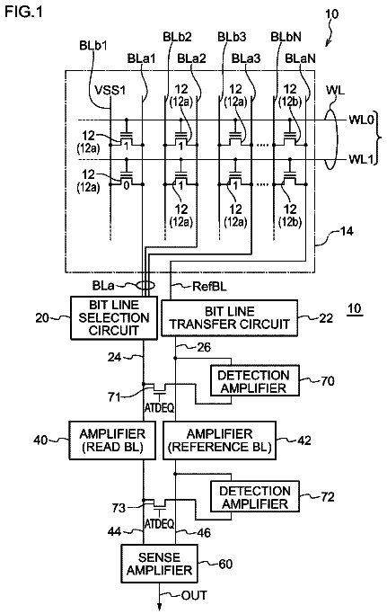
A memory device includes: a transistor array having transistors; and memory elements provided, one for each of the transistors.
US 8,559,214 B2 · Assignee: NEC Corporation · Inventors: Fukami; Shunsuke et al.
Sheet 1 of 59 from the published document. All sheets in the USPTO PDF
A magnetic memory cell is provided with a magnetization record layer and a magnetic tunnel junction section. The magnetization record layer is a ferromagnetic layer having a perpendicular magnetic anisotropy. The magnetic tunnel junction section is used to read data from the magnetization record layer. The magnetization record layer has a plurality of domain wall motion regions.
The magnetic random access memory (MRAM) is expected to be a non-volatile memory device that a high-speed operation is possible, and an infinite rewrite operation is possible, and the research extensively progresses. In the MRAM, magneto-resistance elements are integrated in a memory cell and data is stored based on the magnetization direction of a ferromagnetic layer of the magneto-resistance element. Some proposals of the MRAM have been made with respect to a method of switching (inverting) the magnetization direction of the ferromagnetic layer. The most general MRAM is a current inducing magnetic field write-type MRAM. In this MRAM, a wiring line is arranged around the magneto-resistance element to supply a write current, and the magnetization direction of the ferromagnetic layer of the magneto-resistance element is switched with magnetic field generated with the write current. In thi
1 of 59 drawing sheets so far from the published document, cropped to the drawing. Every sheet is in the USPTO PDF.
What the patent claimed, word for word. All of it is now free to use.
This patent application is the National Phase of PCT/JP2009/071410, filed Dec. 24, 2009, which claims priorities on convention based on Japanese Patent Application No. 2008-330508 filed on Dec. 25, 2008 and Japanese Patent Application No. 2009-229597 filed on Oct. 1, 2009. The disclosures thereof are incorporated herein by reference.
The present invention is related to a magnetic memory device and a magnetic random access memory, and more particular to a domain wall motion-type magnetic memory device and a magnetic random access memory.
The magnetic random access memory (MRAM) is expected to be a non-volatile memory device that a high-speed operation is possible, and an infinite rewrite operation is possible, and the research extensively progresses. In the MRAM, magneto-resistance elements are integrated in a memory cell and data is stored based on the magnetization direction of a ferromagnetic layer of the magneto-resistance element. Some proposals of the MRAM have been made with respect to a method of switching (inverting) the magnetization direction of the ferromagnetic layer.
The most general MRAM is a current inducing magnetic field write-type MRAM. In this MRAM, a wiring line is arranged around the magneto-resistance element to supply a write current, and the magnetization direction of the ferromagnetic layer of the magneto-resistance element is switched with magnetic field generated with the write current. In this MRAM, theoretically, the write operation can be completed in 1 nanosecond or less and it is ideal as a high-speed MRAM. For example, a success in an operation test in 250 MHz is reported: "A 250-MHz 1-Mbit Embedded MRAM Macro Using 2T1 MTJ Cell with Bitline Separation and Half-Pitch Shift Architecture", by N. Sakimura et al. (Solid-State Circuits Conference, 2007, ASSCC' 07, IEEE Asian. p. 216). Moreover, a circuitry suited for 500-MHz operation is proposed in "MRAM Cell Technology for Over 500-MHz SoC", by N. Sakimura et al. (IEEE JOURNAL OF SOLID-STATE CIRCUITS, Vol. 42, 2007, p. 830).
However, the magnetic field required to switch the magnetization direction of a magnetic substance body that has heat stability and external disturbing magnetic field tolerance, is about a few of ten |Oe|. In order to generate such a magnetic field, the write current of 1 mA to several mA is necessary. The chip area is necessarily increased when the write current is large, and also a current consumption amount increases for the write operation. In addition to this, when a memory cell is miniaturized, the write current increases more and a scaling docs not occur. A technique by which the write current can be reduced in correspondence to the miniaturization of the memory cell is required.
As a write technique in which the increase of the write current accompanied with miniaturization can be restrained, the "spin transfer" method is proposed (for example, JP 2005-93488A. and "Current-driven excitation of magnetic multilayers" by J. C. Slonezewski (Journal of Magnetism & Magnetic Materials, 159, L1-L7 (1996)). According to the spin transfer method, spin-polarized current is injected to a ferromagnetic conductor, and the magnetization direction of a conductor is inverted through direct interaction between spin of conduction electrons in a current and the magnetic moment of the conductor (hereinafter, this is referred to as "Spin Transfer Magnetization Switching"). The occurrence of the spin transfer magnetization switching depends on a current density (not an absolute value of the current). Therefore, when using the spin transfer magnetization switching for the data write, a write current is reduced if the size of the memory cell becomes small. That is, the spin transfer magnetization switching method is excellent in the scaling. When the write current is small, the chip region can be made small and a high integration and a large scaling become possible. Here, in the spin transfer magnetization switching method, generally, the write time is longer than in the current inducing magnetic field write-type MRAM (e.g. 1 nsec. or above).
A magnetic shift register using the spin transfer is disclosed in U.S. Pat. No. 6,834,005. The magnetic shift register stores data by using domain walls in a magnetic substance body. A current is injected to pass through the domain wall in the magnetic substance body which is divided into many regions (magnetic domain) and the domain wall is moved with the current. The magnetization direction of each region is handled as the stored data. For example, such a magnetic shift register is used for the storage of a great deal of serial data. It should be noted that the movement of the domain wall in the magnetic substance body is reported in "Real-Space Observation of Current-Driven Domain Wall Motion in Submicron magnetic Wires" by A. Yamaguchi et al., (Physical Review Letters, Vol. 92, pp. 077205-1-4 (2004)).
The "MRAM of a domain wall motion type" which uses domain wall motion by the spin transfer is described in JP 2005-191032A and the WO 2007/020823.
The MRAM described in JP 2005-191032A is provided with a magnetization fixed layer in which magnetization is pinned, a tunnel insulating layer formed on the magnetization fixed layer; and a magnetization record layer formed on the tunnel insulating layer. The magnetization record layer includes a part that the magnetization direction is invertible and another part that the magnetization direction is substantially unchangeable, and therefore, the layer is referred to as not a magnetization free layer but the magnetization record layer. FIG. 1 is a plan view schematically showing a planar structure of the magnetization record layer in JP 2005-191032A. In FIG. 1, the magnetization record layer 100 has a linear shape. Specifically, the magnetization record layer 100 is provided with a junction section 103 which overlaps with the tunnel insulating layer and the magnetization fixed layer, a constricted section 104 in the neighborhood of both ends of the junction section 103, and a pair of magnetization fixed regions 101 and 102 formed in the neighborhood of the constricted section 104. The magnetization fixed regions 101 and 102 have fixed magnetizations directed to opposite directions to each other. Moreover, the MRAM is provided with a pair of write terminals 105 and 106 electrically connected to the pair of magnetization fixed regions 101 and 102, respectively. A current is supplied from the write terminals 105 and 106 to pass through the junction section 103 of the magnetization record layer 100, the constricted section 104 and the pair of magnetization fixed regions 101 and 102.
FIG. 2 is a plan view schematically showing the planar structure of the magnetization record layer 120 in WO 2007/020823. In FIG. 2, the magnetization record layer 120 has a U-character shape. Specifically, the magnetization record layer 120 has a first magnetization fixed region 121, a second magnetization fixed region 122 and a magnetization invertible region 123. The magnetization invertible region 123 overlaps with a pinned layer 130. The first and second magnetization fixed regions 121 and 122 are formed to extend to the Y direction and the magnetization directions are fixed on a same direction. On the other hand, the magnetization inversion region 123 is formed to extend to the X direction and it has the invertible magnetization. Therefore, a domain wall is formed in the boundary B1 between the first magnetization fixed region 121 and the magnetization invertible region 123 or the boundary B2 between the second magnetization fixed region 122 and the magnetization invertible region 123. The first and second magnetization fixed regions 121 and 122 are connected with the current supply terminals 125 and 126, respectively. By using the current supply terminals 125 and 126, it is possible to supply the write current to the magnetization record layer 120. The domain wall is moved in magnetization invertible region 123 according to the direction of the write current. The magnetization direction of the magnetization invertible region 123 can be controlled through this domain wall motion.
However, in the MRAM using a current drive domain wall motion, it is worried that an absolute value of the write current becomes relatively large. In addition to the above Physical Review Letters, Vol. 92, pp. 077205-1-4 (2004), much observations of the current drive domain wall motion are reported. However, the domain wall motion requires a threshold current density of about 1.times.10.sup.8 A/cm.sup.2. In this case, the write current is required to be 1 mA in a case of the width of 100 nm and the thickness of 10 nm in a layer through which the domain wall motion is moved. In order to reduce the write current below this value, the film thickness must be made thinner. In such a case, it is known that the write current density is increased more (for example, "Reduction of Threshold Current Density for Current-Driven Domain Wall Motion using Shape Control" by A. Yamaguchi et al., (Japanese Journal of Applied Physics, vol. 45, No. 5A, pp. 3850-3853 (2006)).
On the other hand, in a device which using a material having the perpendicular magnetic anisotropy that the magnetic anisotropy of the magnetization record layer is perpendicular to a substrate surface, it is shown experimentally that the threshold current density for the domain wall motion is small, compared a case of a material having an in-plane magnetic anisotropy. For example, in "Threshold currents to move domain wall in films with perpendicular anisotropy" by D. Ravelosona et al., (Applied Physics Letters, Vol. 90, 072508 (2007)), the threshold current density in an order of 10.sup.6 A/cm.sup.2 is observed. Also, in "Micromagnetic analysis of current driven domain wall motion in nanostrips with perpendicular magnetic anisotropy" by S. Fukami et al. (J. Appl. Phys. 103, 07E718 (2008)), it is theoretically shown that the threshold current density for the domain wall motion becomes small in the case of the material having the perpendicular magnetic anisotropy, compared of the case of the material having the in-plane magnetic anisotropy. Therefore, it is expected that the write current can be reduced by using the perpendicular magnetic anisotropy material for the magnetization record layer in the MRAM of the current drive domain wall motion type.
As a related technique, in JP 2006-73930A is disclosed a magnetization changing method of a magneto-resistance element using the domain wall motion, a magnetic memory device using the same, and a solid magnetic memory. The magnetic memory device is provided with a first magnetic layer, an intermediate layer and a second magnetic layer and data is stored based on the magnetization directions of the first magnetic layer and the second magnetic layer. In this magnetic memory device, magnetic domains having magnetization directions anti-parallel to each other and a domain wall partitioning the magnetic domains are steadily formed in at least one of the magnetic layers, and by moving the domain wall in the magnetic layer, the position oldie neighboring magnetic domains can be controlled to record the data. The second magnetic layer may have magnetic anisotropy in the perpendicular direction to the film surface.
As mentioned above, in the MRAM using the current drive domain wall motion, it is worried that the absolute value of the write current becomes relatively large. Therefore, the inventor of the present invention considered the reduction of the write current by using the perpendicular magnetic anisotropy material as the magnetization record layer in the MRAM using the current drive domain wall motion.
FIG. 3A and FIG. 3B are a plan view and a sectional view of a magneto-resistance element using the perpendicular magnetic anisotropy material which can be assumed. The magnetization record layer 210 is provided with a magnetization invertible region 213, and a pair of magnetization fixed regions 211a and 211b. Here, symbols of a white circle and a point, symbols of a white circle and a cross, and a white arrow symbol show the magnetization directions of the regions (magnetization invertible region 213 and magnetization fixed regions 211a and 211b in FIG. 3A and FIG. 3B).
The magnetization invertible region 213 overlaps with a tunnel insulating layer 232 and a pinned layer 230 and has a function as a free layer. That is, the magnetization invertible region 213, the tunnel insulating layer 232 and the pinned layer 230 configures a magnetic tunneling junction (MTJ) section. A magnetization fixed region 211a and a magnetization fixed region 211b are connected to one end of the magnetization invertible region 213 and the other end of the magnetization invertible region 213, respectively. A junction section of the magnetization invertible region 213 and the magnetization fixed regions 211a and 211b is provided with the restricted section 215 to which a pin potential forming method disclosed in JP 2005-191032A is applied. The fixed magnetizations opposite in direction to each other must be given to the pair of magnetization fixed regions 211a and 211b. Also, the restricted section 215 functions as a pin potential to the domain wall and the domain wall must be initialized to be the domain wall 212a or 212b in the region in the neighborhood of the restricted section.
Here, the magnetic anisotropy of the magnetization record layer is in the in-plane as shown in FIG. 2. When the magnetization direction is the in-plane, it is easy to initialize the magnetization direction of the magnetization fixed region and the domain wall position to desired states by using a U-shape magnetization record layer. However, when the magnetic anisotropy of the magnetization record layer is perpendicular as shown in FIG. 3A and FIG. 3B, and the magnetization is perpendicular to the in-plane direction, it is difficult to initialize with the external magnetic field even if the magnetization record layer is U-shaped.
Moreover, in the MRAM of the domain wall motion-type, when the pin potential forming method disclosed in JP 2005-191032A is used, the size of the restricted section 215 is small, compared with the magnetization record layer 210, as shown in FIG. 3A and FIG. 3B. Therefore, there is a possibility that the shape is deformed due to the manufacturing variation. In such a case, because the restricted section 215 does not have a desired shape, the domain wall 212 cannot be pinned so that the device cannot function as the magnetic memory. Moreover, it is very difficult to form the restricted section when the device is further miniaturized to make the width of the magnetization record layer narrow. Also, there is a possibility that a work over the lithography limit of the semiconductor process is required.
Patent Literature
[Patent Literature 1]: JP 2005-93488A [Patent Literature 2]: U.S. Pat. No. 6,834,005 [Patent Literature 3]: JP 2005-191032A [Patent Literature 4]: WO 2007/020823 [Patent Literature 5]:
JP 2006-73930
Non-Patent Literature
[Non-Patent Literature 1]: by N. Sakimura et al., Solid-State Circuits Conference, 2007. ASSCC'07. IEEE Asian. p. 216 [Non-Patent Literature 2]: by N. Sakimura et al., IEEE JOURNAL OF SOLID-STATE CIRCUITS, Vol. 42, 2007, p. 830 [Non-Patent Literature 3]: by J. C. Slonezewski, Journal of Magnetism & Mannetic Materials, 159, L1-L7
[Non-Patent Literature 4]: by A. Yamaguchi et al., Physical Review Letters, Vol. 92, pp. 077205-1-4
[Non-Patent Literature 5]: by A. Yamaguchi et al., Japanese Journal of Applied Physics, vol. 45, No. 5A, pp. 3850-3853
[Non-Patent literature 6] by D. Ravelosona et al., Applied Physics Letters, Vol. 90, 072508
[Non-Patent Literature 7]: by S. Fukami et. al., J. Appl. Phys. 103, 07E718
A subject matter of the present invention is to provide a magnetic memory cell and a magnetic random access memory having a structure in which a magnetization fixed region can be formed easily, a pinning site of a domain wall can be formed easily, in an MRAM of a current drive domain wall motion type in which a magnetic anisotropy of a magnetization record layer is in a perpendicular direction.
The subject matter and other subject matters and features of the present invention could be easily confirmed by the following description and the accompanying drawings.
The magnetic memory cell of the present invention is provided with a magnetization record layer and a magnetic tunnel junction section. The magnetization record layer is a ferromagnetic layer having perpendicular magnetic anisotropy. The magnetic tunnel junction section is used to read data in the magnetization record layer. The magnetization record layer is provided with a plurality of magnetic domain wall motion regions.
Also, the magnetic random access memory of the present invention is provided with a plurality of the magnetic memory cells described above and arranged in a matrix. In each of magnetic memories of a plurality of reference cells, a sensor layer has a magnetic anisotropy in a perpendicular direction to a direction of line which links a first domain wall motion region and a second domain wall motion region.
According to the present invention, the magnetization fixed region can be easily formed and the pinning site of the domain wall can be easily formed.
FIG. 1 is a plan view showing a structure of a magnetization record layer disclosed in JP 2005-191032A;
FIG. 2 is a plan view showing a structure of a magnetization record layer disclosed in WO 2007/02083;
FIG. 3A is a plan view of a magneto-resistance element using a perpendicular magnetic anisotropy which is assumed;
FIG. 3B is a sectional view of the magneto-resistance element using the perpendicular magnetic anisotropy which is assumed;
FIG. 4A is a plan view showing a configuration of a magnetization record layer in a magnetic memory device according to a first exemplary embodiment of the present invention;
FIG. 4B is a sectional view showing the configuration of the magnetic memory device according to the first exemplary embodiment of the present invention;
FIG. 5A is a sectional view showing the configuration of the magnetic memory device according to the first exemplary embodiment of the present invention;
FIG. 5B is a sectional view showing the configuration of the magnetic memory device according to the first exemplary embodiment of the present invention;
FIG. 6A is a sectional view showing an initializing method of the magnetic memory device according to the exemplary embodiment of the present invention;
FIG. 6B is a sectional view showing the method of initializing the magnetic memory device according to the exemplary embodiment of the present invention;
FIG. 6C is a sectional view showing the initializing method of the magnetic memory device according to the exemplary embodiment of the present invention;
FIG. 7 is a sectional view showing a data write principle according to the first exemplary embodiment of the present invention;
FIG. 8A is a sectional view showing a data read principle according to the exemplary embodiment of the present invention;
FIG. 8B is a sectional view showing the data read principle according to the exemplary embodiment of the present invention;
FIG. 9 is a diagram showing the configuration of a memory cell according to the first exemplary embodiment of the present invention;
FIG. 10 is a block diagram showing the configuration of an MRAM according to the first exemplary embodiment of the present invention;
FIG. 11 is a block diagram showing a modification of a position relation between a sensor layer and a hard layer of the magnetic memory device according to the exemplary embodiment of the present invention;
FIG. 12 is a block diagram showing a method of stopping a domain wall according to the exemplary embodiment of the present invention:
FIG. 13A is a diagram showing the method of stopping the domain wall according to the exemplary embodiment of the present invention;
FIG. 13B is a diagram showing the method of stopping the domain wall according to the exemplary embodiment of the present invention;
FIG. 13C is a diagram showing the method of stopping the domain wall according to the exemplary embodiment of the present invention;
FIG. 14 is a diagram showing the method of stopping the domain wall according to the exemplary embodiment of the present invention;
FIG. 15 is a diagram showing the method of stopping the domain wall according to the exemplary embodiment of the present invention;
FIG. 16 is a diagram showing the method of stopping the domain wall according to the exemplary embodiment of the present invention;
FIG. 17 is a diagram showing the method of stopping the domain wall according to the exemplary embodiment of the present invention;
FIG. 18 is a diagram showing a method of fixing magnetization according to the exemplary embodiment of the present invention;
FIG. 19 is a diagram showing the method of fixing the magnetization according to the exemplary embodiment of the present invention;
FIG. 20 is a diagram showing the method of fixing the magnetization according to the exemplary embodiment of the present invention;
FIG. 21A is a diagram showing the method of fixing the magnetization according to the exemplary embodiment of the present invention;
FIG. 21B is a diagram showing the method of fixing the magnetization according to the exemplary embodiment of the present invention;
FIG. 22 is a diagram showing the method of fixing the magnetization according to the exemplary embodiment of the present invention;
FIG. 23 is a plan view showing a modification example of the configuration of the magnetization record layer according to the first exemplary embodiment of the present invention;
FIG. 24 is a plan view showing the configuration of the magnetization record layer according to a second exemplary embodiment of the present invention;
FIG. 25A is a plan view showing the configuration of the magnetic memory device according to the second exemplary embodiment of the present invention;
FIG. 25B is a plan view showing the configuration of the magnetic memory device according to the second exemplary embodiment of the present invention;
FIG. 25C is a plan view showing the configuration of the magnetic memory device according to the second exemplary embodiment of the present invention;
FIG. 26 is a graph showing a relation between a relative angle between the magnetization direction of a sensor layer and the magnetization direction of a reference layer and a resistance value of magnetic tunnel junction section;
FIG. 27A is a plan view showing a data write principle according to the second exemplary embodiment of the present invention;
FIG. 27B is a plan view showing the data write principle according to the second exemplary embodiment of the present invention;
FIG. 27C is a plan view showing the data write principle according to the second exemplary embodiment of the present invention;
FIG. 28 is a circuit diagram showing the configuration of the memory cell according to the second to fourth exemplary embodiments of the present invention;
FIG. 29 is a block diagram showing the configuration of the MRAM according to the second to fourth exemplary embodiments of the present invention;
FIG. 30 is a plan view showing the modification example of the configuration of the magnetization record layer according to the second exemplary embodiment of the present invention;
FIG. 31A is a plan view showing the configuration of the magnetization record layer according to a third exemplary embodiment of the present invention;
FIG. 31B is a sectional view showing the configuration of the magnetic memory device according to the third exemplary embodiment of the present invention;
FIG. 32A is a plan view showing the configuration of the magnetic memory device according to the third exemplary embodiment of the present invention;
FIG. 32B is a plan view showing the configuration of the magnetic memory device according to the third exemplary embodiment of the present invention;
FIG. 32C is a plan view showing the configuration of the magnetic memory device according to the third exemplary embodiment of the present invention;
FIG. 33A is a plan view showing the data write principle according to the third exemplary embodiment of the present invention;
FIG. 33B is a plan view showing the data write principle according to the third exemplary embodiment of the present invention;
FIG. 33C is a plan view showing the data write principle according to the third exemplary embodiment of the present invention;
FIG. 34A is a plan view showing the configuration of the magnetization record layer according to a fourth exemplary embodiment of the present invention;
FIG. 34B is a sectional view showing the configuration of the magnetic memory device according to the fourth exemplary embodiment of the present invention;
FIG. 35 is a conceptual diagram showing a relation between the magnetization direction of the reference layer according to the fourth exemplary embodiment of the present invention and a direction of synthetic magnetic field of domain wall motion regions;
FIG. 36A is a plan view showing the configuration of the magnetic memory device according to the fourth exemplary embodiment of the present invention;
FIG. 36B is a plan view showing the configuration of the magnetic memory device according to the fourth exemplary embodiment of the present invention;
FIG. 36C is a plan view showing the configuration of the magnetic memory device according to the fourth exemplary embodiment of the present invention;
FIG. 36D is a plan view showing the configuration of the magnetic memory device according to the fourth exemplary embodiment of the present invention;
FIG. 36E is a plan view showing the configuration of the magnetic memory device according to the fourth exemplary embodiment of the present invention;
FIG. 36F is a plan view showing the configuration of the magnetic memory device according to the fourth exemplary embodiment of the present invention;
FIG. 37A is a plan view showing the data write principle according to the fourth exemplary embodiment of the present invention;
FIG. 37B is a plan view showing the data write principle according to the fourth exemplary embodiment of the present invention;
FIG. 37C is a plan view showing the data write principle according to the fourth exemplary embodiment of the present invention;
FIG. 37D is a plan view showing the data write principle according to the fourth exemplary embodiment of the present invention;
FIG. 37E is a plan view showing the data write principle according to the fourth exemplary embodiment of the present invention;
FIG. 37F is a plan view showing the data write principle according to the fourth exemplary embodiment of the present invention;
FIG. 38A is a plan view showing the configuration of the magnetization record layer according to fifth and sixth exemplary embodiments of the present invention;
FIG. 38B is a sectional view showing the configuration of the magnetic memory device according to the fifth and sixth exemplary embodiments of the present invention;
FIG. 39 is a conceptual diagram showing a relation between the magnetization direction of the reference layer and the direction of the synthetic magnetic field of the domain wall motion regions according to the fifth exemplary embodiment of the present invention;
FIG. 40A is a plan view showing the configuration of the magnetic memory device according to the fifth exemplary embodiment of the present invention;
FIG. 40B is a plan view showing the configuration of the magnetic memory device according to the fifth exemplary embodiment of the present invention;
FIG. 40C is a plan view showing the configuration of the magnetic memory device according to the fifth exemplary embodiment of the present invention;
FIG. 40D is a plan view showing the configuration of the magnetic memory device according to the fifth exemplary embodiment of the present invention;
FIG. 40E is a plan view showing the configuration of the magnetic memory device according to the fifth exemplary embodiment of the present invention;
FIG. 40F is a plan view showing the configuration of the magnetic memory device according to the fifth exemplary embodiment of the present invention;
FIG. 40G is a plan view showing the configuration of the magnetic memory device according to the fifth exemplary embodiment of the present invention;
FIG. 40H is a plan view showing the configuration of the magnetic memory device according to the fifth exemplary embodiment of the present invention;
FIG. 41A is a plan view showing the data write principle according to the fifth exemplary embodiment of the present invention;
FIG. 41B is a plan view showing the data write principle according to the fifth exemplary embodiment of the present invention;
FIG. 41C is a plan view showing the data write principle according to the fifth exemplary embodiment or the present invention;
FIG. 41D is a plan view showing the data write principle according to the fifth exemplary embodiment of the present invention;
FIG. 41E is a plan view showing the data write principle according to the fifth exemplary embodiment of the present invention:
FIG. 41F is a plan view showing the data write principle according to the fifth exemplary embodiment of the present invention;
FIG. 41G is a plan view showing the data write principle according to the fifth exemplary embodiment of the present invention;
FIG. 41H is a plan view showing the data write principle according to the fifth exemplary embodiment of the present invention;
FIG. 42 is a block diagram showing the configuration of the memory cell according to the fifth and sixth exemplary embodiments of the present invention;
FIG. 43 is a block diagram showing the configuration of the MRAM according to the fifth and sixth exemplary embodiments of the present invention:
FIG. 44 is a conceptual diagram showing a relation between the magnetization direction of the reference layer and the direction of a synthetic magnetic field of the domain wall motion regions according to the sixth exemplary embodiment of the present invention;
FIG. 45A is a plan view showing the configuration of the magnetic memory device according to the sixth exemplary embodiment of the present invention;
FIG. 45B is a plan view showing the configuration of the magnetic memory device according to the sixth exemplary embodiment of the present invention;
FIG. 45C is a plan view showing the configuration of the magnetic memory device according to the sixth exemplary embodiment of the present invention;
FIG. 45D is a plan view showing the configuration of the magnetic memory device according to the sixth exemplary embodiment of the present invention;
FIG. 45E is a plan view showing the configuration of the magnetic memory device according to the sixth exemplary embodiment of the present invention;
FIG. 46A is a plan view showing the data write principle according to the sixth exemplary embodiment of the present invention;
FIG. 46B is a plan view showing the data write principle according to the sixth exemplary embodiment of the present invention;
FIG. 46C is a plan view showing the data write principle according to the sixth exemplary embodiment of the present invention;
FIG. 46D is a plan view showing the data write principle according to the sixth exemplary embodiment of the present invention;
FIG. 46E is a plan view showing the data write principle according to the sixth exemplary embodiment of the present invention;
FIG. 47A is a plan view showing the configuration of the magnetization record layer according to a seventh exemplary embodiment of the present invention;
FIG. 47B is a perspective view showing the configuration of the magnetic memory device according to the seventh exemplary embodiment of the present invention; and
FIG. 47C is a plan view showing a layout of the MRAM according to the seventh exemplary embodiment of the present invention.
Hereinafter, a magnetic memory cell and a magnetic random access memory (MRAM) according to the present invention will be described with reference to the attached drawings.
The magnetic memory cell of the present invention is provided with a magnetization record layer which is a ferromagnetic layer having perpendicular magnetic anisotropy, and a magnetic tunnel junction section to read data form the magnetization record layer. The magnetization record layer is provided with a plurality of domain wall motion regions. The data can be stored in accordance with the moved domain walls in the plurality of domain wall motion regions. Also, It is desirable that the magnetic tunnel junction section is provided with a sensor layer which is a ferromagnetic layer having invertible magnetization and having in-plane magnetic anisotropy. Moreover, the magnetization record layer is desirably provided with N+1 (N is a natural number equal to or more than 2) magnetization fixed regions from the 0.sup.th magnetization fixed region to the N.sup.th magnetization fixed region, which have fixed magnetization directions, and N domain wall motion regions from the first domain wall motion region to the N.sup.th domain wall motion region, which have invertible magnetizations and through which the domain walls are movable. It is desirable that the N.sup.th domain wall motion region is connected between the 0.sup.th magnetization fixed region to the N.sup.th magnetization fixed region. At this time, the magnetization record layer stores the data based on a relation of the magnetization directions of the N domain wall motion regions. The magnetization directions of the N magnetization fixed regions other than the 0.sup.th magnetization fixed region are substantially the same and the magnetization direction of the 0.sup.th magnetization fixed region is opposite to the magnetization directions of the N magnetization fixed regions. The projection of the sensor layer to the magnetization record layer overlaps with at least a part of a region of the magnetization record layer between the N domain wall motion regions. The MRAM of the present invention is provided with a plurality of the magnetic memory cells arranged in a matrix. Hereinafter, the magnetic memory cell and the MRAM of the present invention will be described in detail.
First Exemplary Embodiment
In a first exemplary embodiment, the magnetic memory cell and MRAM in a case of N=2 when will be described.
1. Basic Configuration of Magnetic Memory Device
FIG. 4A is a plan view showing an example of the configuration of a magnetization record layer of a magnetic memory device according to the first exemplary embodiment of the present invention. FIG. 4B is a sectional view showing an example of the configuration of the magnetic memory device according to the first exemplary embodiment of the present invention. Here, in FIG. 4A and FIG. 4B, a mark of a white circle and a point, a mark of a white circle and a cross, and a white arrow show the magnetization direction of a concerned region, as used generally. Hereinafter, this is similarly applied to the specification and each drawing.
A magnetic memory device 1 is provided with a magnetization record layer 10 and a magnetic tunnel junction section 20. The magnetization record layer 10 is a ferromagnetic layer which has perpendicular magnetic anisotropy. The magnetization record layer 10 is provided with a plurality of domain wall motion regions, e.g. two domain wall motion regions in the first exemplary embodiment. The magnetic tunnel junction section 20 is provided in the neighborhood of a central region of the magnetization record layer 10 and used to read data stored in the magnetization record layer 10. The details of the magnetization record layer 10 and the magnetic tunnel junction section 20 will be described later. It should be noted that the magnetic memory device 1 may be further provided with a contact layer 30 to electrically connect the magnetization record layer 10 and the magnetic tunnel junction section 20.
The magnetic tunnel junction section 20 is provided with a sensor layer 23, a reference layer 21 and a barrier layer 22.
The reference layer 21 has a fixed magnetization direction and is a ferromagnetic layer which has an in-plane magnetic anisotropy. Here, the in-plane magnetic anisotropy indicates a magnetic anisotropy in x- and y-plane in an example of these figures. Hereinafter, this is applied in the whole specification. It is desirable that the magnetization direction of the reference layer 21 is a longitudinal direction of the magnetization record layer 10. In the example of these figures, the magnetization direction of the reference layer 21 is -x direction of the .+-.x directions which are the longitudinal directions of the magnetization record layer 10. This magnetization direction may be opposite to the above direction. Also, it is desirable that the reference layer 21 is provided with a plurality of ferromagnetic layers which have a laminated ferri coupling, and/or it is desirable that the reference layer 21 is formed from anti-ferromagnetic layers such as Pt--Mn provided in the neighborhood. In order to prevent the magnetization direction of the reference layer 21 from being inverted through write and read operations, it is desirable that the magnetization direction of the reference layer 21 is substantially fixed to one direction.
The sensor layer 23 has an invertible magnetization and is a ferromagnetic layer having the in-plane magnetic anisotropy. The sensor layer 23 is magnetically coupled to the magnetization record layer 10, as described later. Therefore, the magnetization direction of the sensor layer 23 receives in-plane change according to a magnetization state of the magnetization record layer 10 (stored data). In the example of these figures, the magnetization is in the x- and y-plane according to the magnetization state of the magnetization record layer 10 (stored data). The barrier layer 22 is a non-magnetic film or an insulating film provided between the sensor layer 23 and the reference layer 21.
The reference layers 21, the barrier layer 22 and the sensor layer 23 configure a pinned layer, a tunnel insulating layer and a free layer in a magnetic tunnel junction (MTJ). The magnetization direction of the sensor layer 23 is turned in accordance with the data stored in the magnetization record layer 10. On the other hand, the magnetization direction of the reference layer 21 is fixed. Therefore, a resistance value of the magnetic tunnel junction (MTJ) section 20 changes based on the relative relation between the magnetization direction of the sensor layer 23 and the magnetization direction of the reference layer 21. Therefore, by detecting the resistance value of the magnetic tunnel junction section 20, the data stored in the magnetization record layer 10 can be read. That is, the magnetic tunnel junction section 20 can be used as a means of reading the data stored in the magnetization record layer 10.
It is desirable that the reference layer 21 and the sensor layer 23 which have the in-plane magnetic anisotropies contain at least one material selected from the group consisting of Fe, Co and Ni. In addition, it is possible to adjust for a desired magnetic property by adding any of B, C, N, O, Al, Si, P, Ti, V, Cr, Mn, Cu, Zn, Zr, Nb, Mo, Tc, Ru, Rh, Ag, Hf, Ta, W, Re, Os, Ir, and Au. Specifically, Ni--Fe, Co--Fe, Fe--Co--Ni, Ni--Fe--Zr, Co--Fe--B, Co--Fe--Zr--B, and so on are exemplified. Also, it is desirable that the barrier layer 22 is composed of insulating material. Specifically, Mg--O, Al--O, Al--N, Ni--O, Hf--O, and so on are exemplified. Besides, it is possible to attain the present invention even if a non-magnetic material such as a semiconductor material and a metal material is used as the barrier layer 22. Specifically, Cr, Al, Cu, Zn, and so on are exemplified.
The description continues in the full USPTO document.
About 6,428 words. The USPTO PDF has it with every drawing.
Fees are due 3.5, 7.5 and 11.5 years after grant. This patent expired on October 15, 2025, so the fee marked "not paid" was the one that went unpaid.
MAGNETIC MEMORY DEVICE AND MAGNETIC RANDOM ACCESS MEMORY
Filed Dec 2009 · published Oct 2011Magnetic memory device and magnetic random access memory
Filed Dec 2009 · granted Oct 2013Earlier publications, parents and continuations. None of them can still be enforced, or this patent would not be listed.
Prior art cited by the examiner or applicant. Useful when you check your own idea for novelty.
Everything on this page comes from the documents linked above.