Background of the invention
The present invention relates generally to semiconductor processing systems and, more particularly, to a rapid thermal processing (RTP) system and method.
During the manufacture of semiconductor devices, certain processes require the temporary heating of the surface of semiconductor wafers in order to, for example, promote annealing processes or other reactions that may be desired. Conventionally, this heating process, which is here referred to as rapid thermal processing (RTP), is performed by heating the wafer with some form of external energy source such as, for example, a bank of tungsten-halogen lamps or a hot-wall furnace.
Recently, there has been renewed interest in very short heating cycles for processes such as annealing of ion-implantation damage for formation of ultra-shallow junctions. For example, a high temperature process may involve quickly heating a wafer to a peak temperature of approximately 1050.degree. C. then immediately allowing the wafer to cool. Such a process is usually called a spike-anneal. In a spike-anneal process, it is desirable to heat the wafer to a high peak temperature in order to achieve good damage annealing and dopant activation, but the time spent at the high temperature should be as short as possible to avoid excessive dopant diffusion.
The technology trend in the last few years has been to increase the peak temperature of the spike-anneal while simultaneously decreasing the duration of time spent at the peak temperature. This modification is usually accomplished by increasing the heating ramp rate and the cooling rate, as well as by minimizing the switch-off time of the radiant heat source. These approaches help to minimize the peak-width of the spike-anneal, i.e., the time spent by the wafer above a given threshold temperature at which significant diffusion can rapidly occur. The peak-width is often characterized by considering the time spent above a threshold temperature, which is generally defined as 50.degree. C. below the peak temperature of the spike-anneal heating cycle.
Additional methods to further reduce spike-anneal peak-widths are still being developed. For instance, one approach uses pulses of energy to heat the surface of the wafer. This approach takes advantage of the fact that the devices being processed lie within a relatively thin layer near the surface of the wafer and, therefore, there is no fundamental need to heat the entire wafer to the processing temperatures. Surface heating allows very rapid heating of the relatively small thermal mass of the surface region, as well as quick cooling because the heat in the surface region is dissipated into the bulk of the wafer by thermal conduction. Thermal conduction can be a much faster cooling mechanism in comparison to heat loss through radiation or convection from the wafer surface. Pulses of energy are typically applied from pulsed arc-lamps, such as xenon flashlamps, or by scanning an energy beam across the wafer surface. The energy beam may be, for example, a laser, an electron beam or any other type of energy source that may deliver a high power density at the wafer surface. These surface heating approaches are typically used to generate millisecond-duration heat pulses, and the process temperatures employed are higher than the .about.1050.degree. C. temperatures used in conventional RTP. In some cases, annealing at temperatures as high as 1350.degree. C. for approximately one millisecond has been shown to be useful. In the context of the present disclosure, a pulse is understood to refer to a short burst of energy such as, for example, a heat pulse with a duration on the order of milliseconds produced by a pulsed arc lamp. Another example is the use of a pulse of energy from a laser, which may be swept across a wafer surface in order to process a larger area. The laser used in such a context may be a pulsed or a continuous wave (cw) laser. In other words, a pulse is considered to be an energy burst of short duration, wherein the energy burst may be provided from one of a variety of sources.
Although the use of high power energy sources enables such a "millisecond annealing" approach, there are serious practical difficulties that remain to be resolved in this approach. For example, many of the practical pulsed energy sources rely on coupling of radiant energy to the wafer. Consequently, the radiant energy interacts strongly with the optical properties of the wafer. Since wafers are usually patterned with layers and devices that alter the optical properties across the surface of the wafer, the result is uneven power coupling to the wafer surface and potential temperature non-uniformity across the surface of the wafer. As the millisecond-annealing approach requires very high power densities to be applied to the wafer surface, even minor changes in optical coupling can result in large temperature gradients. These temperature gradients lead to non-uniform process results as well as large thermal stresses that can damage the devices on the wafer.
In particular, when a wafer is processed by exposure to energy from a radiant heat source or a beam of energy, non-uniformity may arise if different regions of the wafer absorb different amounts of energy from the incident beam of energy. Such pattern effects may arise, for instance, if the optical or physical properties of the surface vary across the wafer.
Turning now to the drawings, wherein like components are indicated by like reference numbers throughout the various figures where possible, attention is immediately directed to FIG. 1, which illustrates a partial cross sectional view of a typical semiconductor device, generally indicated by a reference numeral 10. It is noted that the figures are not drawn to scale for purposes of clarity. Device 10 includes a wafer 12 with a top surface 14 and a bottom surface 15. Device layers 16 and 18 are deposited on top surface 14. A trench 20 is also etched into top surface 14 of wafer 12 in order to facilitate separation between die, test areas (not shown) and edge exclusion areas (not shown), which are patterned in a different manner from the die. Other features such as edge exclusion regions and test areas may also be present on the wafer surface. Bottom surface 15 of wafer 12 is usually untreated. In general, a semiconductor device, such as device 10, may include thousands of such structures including a variety of patterned layers and trench-like features. Due to the presence of variations, such as represented by device layers 16 and 18 and trench 20, on top surface 14, aforedescribed temperature gradients across the wafer during heat application are common in semiconductor wafers because structures associated with different parts of the wafer vary in physical composition. As a result, optical properties may vary both within any one electronic circuit on the wafer and between different regions of the wafer. Severe variation in energy absorption may arise if different regions on the wafer have different reflectivity or scattering characteristics.
Unfortunately, in semiconductor devices, the thin film structures (such as device layers 16 and 18 of FIG. 1) present on the wafer often exhibit large differences in reflectivity, especially due to optical interference effects that occur in such thin film structures. The thin film stacks often include materials such as silicon dioxide (SiO.sub.2), silicon nitride (Si.sub.3N.sub.4), dielectrics, metals, metal silicides, metal nitrides or carbides, polycrystalline silicon (Si), amorphous Si, single-crystal Si, silicon germanium (SiGe) alloys or germanium (Ge).
Furthermore, semiconductor devices are structured into various line-shapes with three-dimensional topography. Variations in the line shapes and spacing between the lines also lead to variations in the power reflection and absorption. For example, optical energy may be diffracted by patterned features, and arrays of lines may act as grating structures that produce pronounced diffraction and scattering effects, all of which may further contribute to variations in energy absorption. The variations in energy absorption may consequently result in differences in the temperature rise produced or the degree to which a thermal process proceeds.
Another problem with the use of high power energy sources lies in the difficulty of providing adequate process control in terms of the repeatability and uniformity of the heating cycle. Since the process is typically accomplished in an extremely short time duration, it is difficult to apply, for example, conventional feedback control to regulate the heating process. It is also very difficult to apply accurate temperature measurement in the short timescale of the processing, especially when such power energy sources are applied to the wafer. When scanning energy sources are used, the problem is further complicated by the fact that the process occurs in a small region that is difficult to observe and control by conventional measurement and control techniques. Since the qualities of the energy sources may change or drift over time, there is no simple way to ensure that repeatable and uniform processing occurs at all points on all of the semiconductor wafers being processed.
Yet another problem arises from the challenging requirements of the high power energy sources themselves. Simple heat-flow calculations have shown that, for a one millisecond process time, it is typically necessary to deliver approximately 15 J/cm.sup.2 to the wafer surface. For example, for a 300 millimeter diameter wafer, the minimum total energy delivered to the wafer is approximately 11 kJ. If the energy is delivered to the wafer from, for instance, a bank of flashlamps, then energy is lost through absorption in the process chamber walls and other components, and, additionally, there is significant loss in the conversion of electrical energy to radiant emission from the lamps. As a result, the heating system typically needs to provide energy pulses of at least 50 kJ, which leads to rather large equipment. The alternative approach of scanning a focused energy beam across the wafer surface requires very expensive equipment. For example, if a high power laser is used, then expensive optics and wafer mounting fixtures are required. Moreover, the scanning approach limits the throughput in terms of the number of wafers that may be processed per hour.
Some types of energy sources used in thermal processing include electromagnetic energy sources, such as lamps, hot objects, lasers and microwave or millimeter wave sources, hot streams of gas, flames, particle beams (including streams of electrons or ions), plasmas, energetic atoms and radicals. Typical lamps may include tungsten halogen lamps or arc lamps. An arc lamp may include a flashlamp containing an inert gas such as xenon, argon, krypton, neon or mixtures of these gases. Lamps may be used in a direct current (DC) or pulsed mode (such as a flashlamp). In the pulsed mode, flashlamps usually produce pulses of energy with durations between 1 .mu.s and 100 ms. One example of a suitable energy source is the high energy arc lamp manufactured by Mattson Technology, Canada.
The energy from lamps may be delivered to the wafer with the assistance of reflectors and other optical components. In many cases, it may be convenient to arrange the illumination such that all of the wafer may be exposed to the radiation in one pulse of energy. However, if so desired, the radiant energy may be delivered to various regions of the wafer sequentially while the wafer and/or energy source are moved with respect to each other between periods of illumination.
As will be seen hereinafter, the present invention provides a remarkable improvement over the prior art as discussed above by virtue of its ability to provide short heating cycles at high temperatures with increased performance while resolving the aforedescribed problems present in the current state of the art.
Summary of the invention
As will be described in more detail hereinafter, there is disclosed herein a method performed for heat treating a wafer in a process chamber as an intermediate part of an overall multi-step technique for processing a semiconductor wafer. The method of the present invention includes applying an energy transfer layer to at least a portion of the wafer, and exposing the wafer to an energy source in the process chamber in a way which subjects the wafer to a thermal profile having at least a first elevated temperature event and such that the energy transfer layer influences at least one part of the thermal profile. The method further includes, in time relation to the thermal profile, removing the energy transfer layer in the process chamber at least sufficiently for subjecting the wafer to a subsequent step.
The energy transfer layer of the present invention serves, for example, to absorb an emitted energy from the energy source. Alternatively, at least an initial portion of exposing the wafer subjects the wafer to an inert gas ambient and the removing of the energy transfer layer is initiated by introducing a reactive gas ambient into the process chamber. As another option, the energy transfer layer is oxidizable and removing the energy transfer layer includes causing the energy transfer layer to oxidize in cooperation with the exposing. As another alternative, removing is performed using a chemical reaction with the energy transfer layer which is exothermic so as to contribute heat to the thermal profile. The energy transfer layer may also be patterned in a way which enhances, for example, removing thereof.
In another aspect of the invention, in an overall multi-step technique for processing a semiconductor wafer, an intermediate condition of the wafer that is useful for heat treating the wafer in a process chamber as part of the overall multi-step technique is produced. The intermediate condition of the wafer includes a material layer temporarily applied to at least a portion of the wafer such that exposing the wafer to an energy source in the process chamber subjects the wafer to a thermal profile having at least a first elevated temperature event and such that the material layer influences at least one part of the thermal profile by undergoing a reaction in a predetermined way at least as the material layer is removed from the wafer so as to be substantially absent from a target structure being formed on the wafer.
In yet another aspect of the invention, in an overall multi-step technique for processing a semiconductor wafer, a method is performed for heat treating the wafer as an intermediate part of the overall multi-step technique in which the wafer is exposed to an energy source arrangement. The method includes applying a material layer temporarily to at least one portion of the wafer such that the material layer exhibits a given response to the energy source arrangement. The method also includes subjecting at least the material layer to a stream containing energetic species such that the material layer thereafter exhibits a modified response to the energy source arrangement. The method further includes exposing the wafer including the material layer having the modified response to the energy source arrangement to perform the heat treating, and removing the material layer.
In still another aspect of the invention, in an overall multi-step technique for processing a semiconductor wafer, a method is performed for heat treating the wafer in a process chamber as an intermediate part of the overall multi-step technique. The method includes applying a first material layer to at least a portion of the wafer, and subjecting the first material layer to a second material in cooperation with exposing the first material to an energy source in the process chamber in a way which causes the first material layer to react with the second material so as to generate heat which induces a temperature rise of the wafer. The second material may be, for example, provided in a gaseous form in the process chamber for reaction with the first material, or applied to an area of the wafer to cooperate with the first material layer on the portion of the wafer to produce the reaction. The temperature rise may contribute, at least in part, to a desired material transformation of the wafer.
In a further aspect of the invention, in an overall multi-step technique for processing a semiconductor wafer, a method is performed for heat treating the wafer in a process chamber as an intermediate part of the overall multi-step technique. The method includes applying a material layer to at least a portion of the wafer, and exposing the material layer to an energy source in the process chamber in a way which causes the material layer to decompose into at least two by-products, thereby releasing thermal energy.
Brief description of the drawings
The present invention may be understood by reference to the following detailed description taken in conjunction with the drawings briefly described below. It is noted that, for purposes of illustrative clarity, certain elements in the drawings may not be drawn to scale. Furthermore, descriptive nomenclature such as, for example, vertical, horizontal and the like applied to the various figures is used for illustrative purposes only and is in no way intended as limiting useful orientations of the structure or device described.
FIG. 1 is a diagrammatic fragmentary illustration, in partial cut-away view, of a semiconductor device, shown here to indicate the variety of topology potentially present on the surface of a typical semiconductor wafer.
FIG. 2 is a diagrammatic illustration, in elevation, of a lamp-based thermal processing apparatus suitable for use in thermal processing of semiconductor wafers in accordance with the present invention.
FIG. 3 is a diagrammatic illustration, in elevation, of a laser-based thermal processing apparatus suitable for use in thermal processing of semiconductor wafers in accordance with the present invention.
FIG. 4 is a graph showing the calculated absorptivity spectra for several thin film configurations commonly used on a semiconductor wafer.
FIG. 5 is a composite graph showing the calculated absorptivity spectra for several single layer coatings on a substrate as well as the calculated, normalized spectral power density for a blackbody at 8000K.
FIG. 6 is a graph showing the calculated variation in the integrated absorptivity for a single layer coating on a substrate at a variety of film thicknesses.
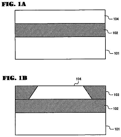
FIGS. 7A-7M are diagrammatic fragmentary illustrations, in partial cut-away view, of a variety of energy transfer layer configurations for use with a semiconductor device, such as that shown in FIG. 1.
FIGS. 8-18 are graphs showing the calculated absorptivity spectra and integrated absorptivity for a variety of coating configurations on a silicon wafer.
FIG. 19 is a diagrammatic fragmentary illustration, in partial cut-away view, of a device on which a patterned energy transfer layer has been deposited, shown here to illustrate a light trapping effect by which the patterned energy transfer layer may increase absorption of incident radiation.
FIGS. 20(A)-(H) and 21 are diagrammatic illustrations of possible configurations for 1-D and 2-D patterns suitable for use with the patterned energy transfer layer concept.
FIG. 22 is a flow diagram illustrating one approach for employing an energy transfer structure in a semiconductor wafer processing work flow.
FIG. 23 is a diagrammatic illustration of an integrated processing system in which the deposition, thermal processing and etching/cleaning steps are performed in three separate chambers connected with a central wafer handling unit that passes the wafer between the chambers.
FIGS. 24-28 are graphs showing the thermal cycle schemes for a variety of thermal processing work flows.
FIGS. 29-31 are diagrammatic fragmentary illustrations, in partial cut-away view, of a MOS transistor and its processing thereof in accordance with the present invention.
FIGS. 32-35 and 36(A)-(E) are diagrammatic illustrations of possible patterning approaches suitable for use with the energy transfer layer concept when two different materials are used in the reactive layer.
Detailed description
The following description is presented to enable one of ordinary skill in the art to make and use the invention and is provided in the context of a patent application and its requirements. Various modifications to the described embodiments will be readily apparent to those skilled in the art and the generic principles herein may be applied to other embodiments. Thus, the present invention is not intended to be limited to the embodiment shown but is to be accorded the widest scope consistent with the principles and features described herein.
It is important to appreciate that concerns with respect to non-uniformity across the wafer surface in the thermal processing of semiconductor wafers are especially important in sensitive processing steps such as the annealing of ion implantation damage and the electrical activation of implanted dopant species. For instance, such processes are vital in the formation of source and drain regions of advanced transistors. These processes must be very carefully controlled such that the electronic devices function as designed, and so that different devices across the wafer have uniform characteristics.
Other thermal processes that involve diffusion, annealing, chemical bonding rearrangements, chemical reactions or phase changes, may also require very strict process control. Examples of such processes include, for instance, metal silicide formation and annealing. The semiconductor material involved in such processing include, for example, Si, Ge, alloys of Si and Ge, and other compound semiconductors such as gallium arsenide (GaAs), indium phosphide (InP), indium antimonide (InSb), aluminum arsenide (AlAs), gallium nitride (GaN), silicon carbide (SiC) and alloys of these materials. Such materials may be employed directly on the semiconductor wafer or may be present as a thin film over an insulating substrate or an insulating film on top of another substrate. For example, a semiconductor film may be formed in a silicon-on-insulator configuration, in which a thin Si film is formed on top of a SiO.sub.2 layer, which in turn is disposed on top of a silicon substrate.
One aspect of the present invention is based on the concept of applying a film of material to the wafer surface, then inducing a chemical reaction or a physical change in that layer to either generate heat (exothermic reaction) or absorb heat (endothermic reaction). This film of material essentially acts as an energy transfer layer/structure which assists in the transfer of energy into and/or out of the wafer. For instance, in an exothermic reaction, the heat released from the energy transfer layer by the reaction diffuses into the surface of the semiconductor wafer and thereby induces a temperature rise to induce the desired process in the wafer. In an endothermic reaction, heat is diffused out from the wafer surface, thereby lowering the wafer temperature in order to, for instance, quench a high temperature process in progress. In other cases, the energy transfer layer may act as an absorber layer, which facilitates the coupling of external energy onto a wafer surface. Additionally, an energy transfer layer/structure may include an arrangement of films or "sub-layers" that cooperate in order to achieve a particular objective. Furthermore, the energy transfer layer/structure may be segmented, as will be discussed in detail at an appropriate point in the following narrative.
As an example of an exothermic reaction in RTP, the energy transfer layer RTP concept may be applied to the process of annealing an ion-implanted layer to create an ultra-shallow junction (USJ) structure. This use of the energy transfer layer in a heat-generation/absorption application may be referred to as the reactive RTP concept hereinafter. As an exemplary reactive layer, a film of carbon may be applied to the surface of the wafer by a deposition process. The carbon-coated wafer may then be loaded into an RTP system and heated to an elevated temperature (e.g., 1000.degree. C.) in an inert ambient, such as in nitrogen gas. A reactive gas, such as oxygen, is then admitted to the RTP chamber. The oxygen gas rapidly oxidizes the carbon film, thus releasing heat into the wafer surface. The heat increases the wafer surface temperature and, consequently, the ion-implant is annealed. This exothermic reaction terminates when all of the carbon has been consumed and removed from the wafer surface in a gaseous form. The wafer is then allowed to cool and removed from the RTP system.
For the above exothermic reaction approach to be useful, two requirements must be met. Firstly, the reaction must provide sufficient energy to heat the wafer surface adequately while releasing that energy into the wafer surface over a timescale that is sufficiently short, such that the heat is dissipated by thermal conduction, convection or radiation.
In the aforedescribed example of the carbon film, a 1-.mu.m thick film of carbon coating the surface of a wafer has a total volume of 10.sup.-4 cm.sup.3 for every square centimeter of wafer surface area. Assuming that the carbon film has the density of graphite (i.e., .about.2.26 g/cm.sup.3), then there is approximately 2.26.times.10.sup.-4 g/cm.sup.2 of carbon on the wafer surface. Since a mole of carbon weighs approximately 12 g, there are .about.1.88.times.10.sup.-5 mol/cm.sup.2 of carbon on the wafer surface. The combustion reaction: C+O.sub.2.fwdarw.CO.sub.2 releases 393.5 kJ/mol, so the conversion of 1-.mu.m thick film of carbon on the wafer surface to CO.sub.2 releases an energy per unit area of 393.5.times.10.sup.3.times.1.88.times.10.sup.-5=7.4 J/cm.sup.2. This amount of energy is a useful amount of heat for producing a temperature rise in the surface of a silicon wafer. Therefore, by this calculation, the energy available from combustion of a carbon film in oxygen should be large enough to be useful in RTP.
It is recognized that not all of the heat produced in the above exothermic reaction would be directed into the wafer, since the reaction product tends to carry away a fraction of the produced energy. However, as a broad concept, Applicant has found that such chemical reactions are able to generate useful heat for promoting the surface reactions necessary in processing a semiconductor wafer.
The second requirement for the exothermic reaction approach to be useful is that the rate at which heat is generated by the chemical reaction is large compared to that at which heat is lost from the reacting region and the semiconductor wafer itself. For instance, if it is desired to heat the wafer surface over a millisecond timescale, then the 1-.mu.m layer of carbon in the above example must be consumed in a similar timescale. This requirement places limitations on the kinetics of the reaction and the way in which the reaction is carried out.
Methods for Accelerating Reactions
Various methods to accelerate the rate of exothermic reaction may be implemented, as described in detail immediately hereinafter.
(A) The wafer may be pre-heated to a reaction temperature before the reactive gas (i.e., oxygen in the present example) is admitted into the RTP chamber. The pre-heating promotes the sudden combustion of the carbon film when the hot carbon surface is exposed to oxygen or another reactive species. The reaction temperature may also be selected to optimize the reaction rate.
(B) The ramp rate for heating the wafer in the oxidizing ambient may be made large such that most of the exothermic reaction occurs in a temperature regime that favors the rapid release of heat. This approach is particularly useful if there are difficulties in providing an adequately fast switching of the ambient gas to initiate the reaction.
(C) A pulse of heat may be applied to the wafer surface to initiate a fast reaction. This pulse may be applied from the main heat source or from a secondary pulsed energy source. This approach may be used to provide a hybrid method for pulsed anneals. Namely, some of the energy for the surface heating may be provided by the energy pulse while additional heat is provided by the chemical reaction. The pulse of energy may be provided by, for example, flashlamps, lasers or other forms of pulsed electromagnetic radiation or particle beams.
(D) The reactive species may be optimized to the specific chemical reaction used in the process. Particularly, in the present carbon oxidation example, a wide variety of approaches may be adopted. For example, the reactive oxygen gas may be provided in the form of oxygen molecules, oxygen ions, oxygen radicals, ozone (O.sub.3) or other oxidizing species and chemicals. The desired species may be supplied by a number of approaches including, but not limited to, direct generation within or near the process chamber. For instance, highly reactive species may be generated through photo-excitation of gases with high energy photons or particles, plasmas, flames and chemical reactions in the gas phase. The gases may be exposed to these excitation methods either directly within the RTP chamber itself or, alternatively, the desired species may be generated separately then transferred into the chamber. The reactive species may also be formed by mixing a given combination of gases together to provide the process ambient.
(E) A stimulating energy may be applied directly to the wafer itself in order to, for example, promote a reaction at the wafer surface. The stimulating energy may be provided from photons, such as ultraviolet (UV), visible or infrared (IR) radiation, or other electromagnetic waves, such as radio frequency (RF) or microwave excitation. Energy sources for stimulating reactions may include, but are not limited to, lasers, lamps, flash-lamps, X-ray generators, RF and microwave power sources. The reactive processes may also be stimulated by exposure to a plasma or particle beams, such as electron or ion radiation or even beams of energetic neutral species.
(F) The reactant pressure may be optimized in order to increase the reaction rate. In some cases, the chamber pressure may be increased to accelerate the reaction rate. In other cases, it may be desirable to decrease the chamber pressure in order to optimize, for example, the flow of reactants and reaction by-products towards and away from the wafer surface.
(G) The design of the process chamber may be optimized to achieve gas flow behavior that facilitates the reactions. For example, a pulse of the reactive gas may need to be provided to the surface of the wafer in a rapid and uniform manner. In this case, it is useful to design a chamber in which the reactive gas is introduced using, for instance, a shower head configuration facing the wafer such that the reactive species concentration is uniform across the wafer surface. Additionally, the gas flows and pressures may be engineered to allow rapid introduction of reactive species and their removal through suitable exhaust arrangements. For instance, it may be useful in some applications to form high velocity beams of reactive species that may be directed at the wafer surface. This approach may be combined with the use of a low pressure environment that allows rapid removal of reaction by-products from the wafer surface.
(H) Catalytic methods may be used to promote the reaction which generates the heat. The catalyst may be included within the deposited energy transfer layer structures on the wafer surface or provided within a gas introduced into the chamber.
(I) The structure of the energy transfer layer may be optimized to allow rapid reaction or to improve the repeatability and uniformity of the process. For instance, factors such as, but not limited to, thickness, composition, microstructure, density, porosity and surface texture of the film may all influence the reaction rate.
For example, combinations of films, such as multi-layer structures, may also be optimized in view of acceleration of the reaction rate, especially if one material on its own cannot meet all of the requirements for optimization. In particular, it is recognized that the structure of the energy transfer layer will influence how well the heat is transferred to the semiconductor wafer. In this sense, optimization of film characteristics such as the thermal conductivity may also be influential in accelerating the reaction rate.
As another example, the way in which the energy transfer layer absorbs and radiates heat and light may also be optimized to promote efficient processing. For example, it may be useful to design the film's optical properties so as to enable uniform and efficient coupling of the radiation used to heat the wafer or to initiate the reaction. This effect may be useful, for instance, if a flash-lamp or laser source is used to provide a pulse of heat to the wafer surface, either to stimulate a reaction or provide heat to the wafer surface.
As yet another example, the energy transfer layer may be designed to absorb a specific lamp spectrum or laser wavelength. Such coatings may also be patterned if it is necessary to vary the energy delivered to different regions on the wafer surface. For example, this approach is useful if certain regions of the wafer surface are more sensitive to thermal exposure than other regions. In another case, it may be useful to add a transparent surface layer which allows transmission of some fraction of stimulating radiation to a depth within a multi-layer reactive coating structure, for example, to deposit heat or high-energy photons to that depth.
(J) The energy transfer layer itself may be designed to have optical properties that improve the ability to measure or control the temperature of the wafer being processed. For example, a coating may be designed to exhibit a known spectral emissivity at a given wavelength. In this case, a pyrometer that senses radiation at the given wavelength may be conveniently used to determine the wafer temperature.
(K) The energy transfer layer may be designed to provide additional functionality in addition to the exothermic or endothermic reaction. That is, although the energy transfer layer RTP concept emphasizes the emission or absorption of heat from an energy transfer layer formed on the wafer surface, the energy transfer layer may be used to assist in thermal processing of the wafer in various other ways. For example, when the properties of the energy transfer layer are engineered as in the approaches (I) and (J) described above, an energy transfer layer may actually perform a function more concerned with improving the control or uniformity of a thermal process than with merely generating or absorbing heat.
One instance in which this added functionality concept is useful is in mitigating the so-called "pattern effects" in wafer processing. In particular, the processing of patterned wafers can pose a problem in any processing approach that involves the use of optical radiation to heat the wafer because the patterns on the wafer disturb the power coupling into the wafer as well as the heat loss from the wafer, thereby leading to large temperature non-uniformities known as pattern effects. A possible solution to the pattern effect problem is to deposit an extra film over the wafer surface for improving the coupling of radiation, thus reducing non-uniformities (i.e., in an approach similar to the ninth approach described above). However, the extra processing steps of depositing this extra film, then removing the extra film, add processing costs. The energy transfer layer concept is useful in this capacity since the extra film may be formed or removed by a chemical reaction.
As a specific example, an opaque film of carbon may be formed on a wafer surface to assist in the absorption of a pulse of heat energy at the wafer surface. Then, the carbon film may be removed either during or immediately following the pulse thermal process by exposing the wafer to a supply of oxygen gas.
It is recognized that, if the chemical reaction is rapid enough, then the heat generated by the combustion process may be useful in assisting the pulse heating process. However, even if the opaque film were removed by a slower oxidization process (e.g., at a lower temperature or after introduction of a different gas ambient), a properly designed film would not need to be removed in an additional stage of processing. In this mode of processing, the key features of the energy transfer layer concept are that the energy transfer layer improves the heating process while being capable of convenient removal by a chemical reaction, which may even be performed in the same process step as the heating process.
Such an energy transfer layer may additionally be used to improve temperature measurement and control, for example, by allowing more accurate and repeatable measurements as suggested in approach (J) described above. Furthermore, the energy transfer layer may be designed to yield additional benefits by altering the thermal radiative properties of the wafer surface, such as providing an increase in emissivity, which increases the cooling rate of a wafer during a spike-anneal process.
Still further, the energy transfer layer may also be formed within the process chamber, prior to exposure to the heating process of interest, then removed by a second reaction. In this case, the energy transfer layer may be formed by, for example, a deposition process or through a chemical or physical conversion of another material already deposited on the wafer.
The aforedescribed approaches may be used in combination to optimize the reaction acceleration in each instance. Although the above approaches have been described in the context of the example of carbon and oxygen reactions, the same approaches may be applied to other reactions including, but not limited to, alternative materials and alternative reactions, such as solid-phase reactions and phase changes.
The foregoing discussion has so far concentrated on the use of exothermic reactions to produce pulses of heat in the wafer. As mentioned previously, it is also sometimes advantageous to use an endothermic process to provide a method for cooling the wafer surface. For example, in the spike-anneal approach discussed above, it is desirable to increase the cooling rate of the wafer surface, along with increases in the heating rate, so as to further reduce the peak width of the spike-anneal. Heat loss from the wafer is usually limited to that achievable by a combination of heat radiation, convection and conduction. By promoting an endothermic process at the wafer surface, the heat loss may be further increased so as to accelerate the cooling rate.
Again considering the example of a wafer with a carbon layer deposited on the surface, it is noted that the reaction of the carbon layer with carbon dioxide yields an endothermic process: C+CO.sub.2.fwdarw.2CO This process absorbs .about.172.5 kJ/mol. Following a similar calculation to that used in the aforedescribed exothermic reaction, it may be calculated that the above reaction using a one micron-thick film of carbon absorbs .about.3.2 J/cm.sup.2 of energy from the wafer surface.
The description continues in the full USPTO document.
 Lapsed, fee not paid6 drawings