Lapsed, fee not paid3 drawings
Lapsed, fee not paid
Process for making an embossed web
US 8,557,169 B2 · Assignee: The Procter & Gamble Company · Inventors: Gross; Sarah Beth et al.
Overview
Sheet 1 of 10 from the published document. All sheets in the USPTO PDF
Abstract From the patent
A process for making an embossed web includes providing a precursor web a first forming structure having a plurality of discrete first forming elements and a first pressure source and applying pressure between the first pressure source and the first forming structure to force the precursor web to conform to the first forming elements of to form a first embossed web having a plurality of first discrete extended elements. The first embossed web is then provided between a second forming structure having a plurality of discrete second forming elements and a second pressure source and pressure is applied between the second pressure source and the second forming structure to force the first embossed web to conform to the second forming elements to form a second embossed web having a plurality of second discrete extended elements. The resulting embossed web has a plurality of first and second discrete extended elements.
Why it's free to use
- The USPTO Official Gazette of December 9, 2025 lists it as expired on October 15, 2025 for an unpaid maintenance fee.
- It isn't on any reinstatement notice published since.
- Its 1 US relative has also lapsed, expired or never issued.
- We check US rights only. Check foreign counterparts before selling abroad.
FiledSeptember 10, 2010
GrantedOctober 15, 2013
Expired (fee)October 15, 2025
Application number12/879567
Classification (CPC)B29C66/82661 +7 more
Length20 claims · 26 pages
Background From the patent
Web materials, such as thermoplastic films, have a variety of uses including component materials of absorbent articles (such as topsheets and backsheets), packaging (such as flow wrap, shrink wrap, and polybags), trash bags, food wrap, dental floss, wipes, electronic components, and the like. For many of these uses of web materials, it can be beneficial for the web material to have a textured surface which can provide the surface of the web material with a desirable feel, visual impression, and/or audible impression. Polymeric webs exhibiting a soft and silky tactile impression can be made via a vacuum forming process or a hydroforming process. With a typical vacuum forming process, a precursor web is heated and placed over a forming structure. Then a vacuum forces the precursor web to conform to the texture of the forming structure. The resulting polymeric web has texture that can provi
Drawings 10
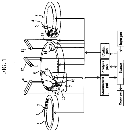
1 of 10 drawing sheets so far from the published document, cropped to the drawing. Every sheet is in the USPTO PDF.
Figures as described
- FIG. 1 is a top view of a forming structure in accordance with an embodiment of the disclosure
- FIG. 2A is a perspective view of a forming structure in accordance with an embodiment of the disclosure illustrating the distinction between apertures and depressions
- FIG. 2B is an enlarged perspective view of a portion of the forming structure having discrete protruded elements
- FIG. 3 is a schematic illustration of a continuous process for making an embossed web in accordance with an embodiment of the disclosure
- FIG. 4 is a schematic illustration of a process in accordance with an embodiment of the disclosure, illustrating a static gas pressure plenum
- FIG. 5 is a perspective view of a portion of an embossed web formed by a process in accordance with an embodiment of the disclosure
- FIG. 6 is a cross-sectional view of a portion of an embossed web formed by a process in accordance with an embodiment of the disclosure
- FIG. 8A is a photograph of a first embossed web having first discrete extended elements formed by a process in accordance with an embodiment of the disclosure
- FIG. 9 is a photograph of a second embossed web having first and second discrete extended elements formed by a process in accordance with an embodiment of the disclosure
Claims 20 total, 1 independent
What the patent claimed, word for word. All of it is now free to use.
- 1Independent claimA process for making a polymeric embossed film web, the process comprising: feeding a precursor polymeric film web between a first pressure source and a first forming structure comprising a plurality of first forming elements; applying pressure from the first pressure source against the precursor web opposite the first forming structure creating a pressure differential across the precursor web sufficient to conform the precursor web to the first forming elements of the first forming structure, thereby forming a first embossed web comprising a plurality of first discrete extended elements having open proximal ends; feeding the first embossed web between a second pressure source and a second forming structure comprising a plurality of second forming elements; and applying pressure from the second pressure source against the first embossed web opposite the second forming structure creating a pressure differential across the first embossed web sufficient to conform the first embossed web to the second forming elements of the second forming structure, thereby forming a second embossed web comprising a plurality of second discrete extended having open proximal ends, wherein the first and second forming elements are selected, from the group consisting of discrete protruded elements, discrete apertures, discrete depressions, and combinations thereof, the discrete protruded elements having a height and the discrete apertures and discrete depressions having a depth, the height and the depth being at least substantially equal to a thickness of the precursor web, wherein at least one of the first and second pressure sources is a static gas pressure plenum, and wherein the first and second pressure sources are not velocity pressure sources, and wherein the precursor polymeric film web is free of cellulose.
- 2The process of claim 1, wherein at least a portion of the second discrete extended elements are disposed adjacent to the first discrete extended elements.
- 3The process of claim 1, wherein the gas comprises a gas selected from the group consisting of nitrogen, carbon dioxide, and mixtures thereof.
- 4The process of claim 1, wherein at least one of the first and second pressure source is a compliant substrate.
- 5The process of claim 4, wherein the compliant substrate comprises a material selected from the group consisting of elastomers, felts, liquid filled bladders, gas filled bladders, and combinations thereof.
- 6The process of claim 1, wherein the first and second pressure sources are the same pressure source.
- 7The process of claim 1, wherein the first pressure source is a static pressure plenum and the second pressure source is a compliant substrate.
- 8The process of claim 1, wherein the first pressure source is a compliant substrate and the second pressure source is a static pressure plenum.
- 9The process of claim 1, wherein the first forming elements and/or the second forming elements have an average edge-to-edge spacing of about 50 microns to about 800 microns.
- 10The process of claim 1, wherein the first forming elements comprise discrete protruded elements and the second forming elements comprise at least one of discrete apertures and discrete depressions.
- 11The process of claim 1, wherein the first forming elements comprise at least one of discrete apertures and discrete depressions and the second forming elements comprise discrete protruded elements.
- 12The process of claim 1, wherein the first and second forming elements comprise discrete protruded elements having substantially the same shape, size, aspect ratio, and edge-to-edge spacing.
- 13The process of claim 1, wherein the first and second forming elements comprise discrete protruded elements, and the discrete protruded elements of the first forming elements have at least one of a different shape, different size, different aspect ratio, and different edge-to-edge spacing as the discrete protruded elements of the second forming elements.
- 14The process of claim 1, wherein the first and second forming elements comprise at least one of discrete apertures and discrete depressions having substantially the same shape, depth, width, and edge-to-edge spacing.
- 15The process of claim 1, wherein the first and second forming elements comprise at least one of discrete apertures and discrete depressions, and at least one of the discrete apertures and discrete depressions of the first forming elements have at least one of a different shape, different depth, different width, and different edge-to-edge spacing as at least one of the discrete apertures and depressions of the second forming elements.
- 16The process of claim 1, wherein the first and second forming structures are the same forming structure having the same forming elements.
- 17The process of claim 1, comprising applying pressure from the first pressure source for a first dwell time, and applying pressure from the second pressure source for a second dwell time.
- 18The process of claim 17, wherein the first and second dwell times are the substantially equal.
- 19The process of claim 17, wherein the first and second dwell times are different.
- 20The process of claim 1, wherein the temperature of the precursor web and the first embossed web during the process is less than the melting point of the precursor web.
Description
Field of the invention
The invention relates to a process for making an embossed web comprising a plurality of discrete extended elements.
Background of the invention
Web materials, such as thermoplastic films, have a variety of uses including component materials of absorbent articles (such as topsheets and backsheets), packaging (such as flow wrap, shrink wrap, and polybags), trash bags, food wrap, dental floss, wipes, electronic components, and the like. For many of these uses of web materials, it can be beneficial for the web material to have a textured surface which can provide the surface of the web material with a desirable feel, visual impression, and/or audible impression.
Polymeric webs exhibiting a soft and silky tactile impression can be made via a vacuum forming process or a hydroforming process. With a typical vacuum forming process, a precursor web is heated and placed over a forming structure. Then a vacuum forces the precursor web to conform to the texture of the forming structure. The resulting polymeric web has texture that can provide a soft and silky tactile impression, depending upon the texture of the forming structure and degree of conformation. While a vacuum forming process can be suitable for making a soft and silky polymeric web, a vacuum forming process is typically limited with respect to the amount of pressure capable of being exerted onto a precursor web. As a result, it is usually required to heat a precursor film to significantly soften or melt the precursor film prior to placement on the forming structure in order to vacuum form the precursor film to the forming structure. A vacuum forming process is therefore an inefficient process in terms of how fast the process can be performed due to the heating step and the limited pressures generated by the process.
With a typical hydroforming process, a precursor web is placed over a forming structure and high pressure and high temperature water jets force the precursor web to conform to the texture of the forming structure. The resulting polymeric web can have texture that can provide a soft and silky tactile impression, depending upon the texture of the forming structure. A hydroforming process, although capable of producing soft and silky polymeric webs, is typically a costly and inefficient process involving the use of high pressure and high temperature water jets and subsequent drying steps, including dewatering steps.
Embossing is a process that typically involves the act of mechanically working a substrate to cause the substrate to conform under pressure to the depths and contours of a pattern engraved or otherwise formed on an embossing roll. It is widely used in the production of consumer goods. Manufacturers use the embossing process to impart a texture or relief pattern into products made of textiles, paper, synthetic materials, plastic materials, metals, and wood.
Embossing processes have been used to provide texture to polymeric films. However, such embossing processes typically require extruding a molten resin onto a forming structure or heating a precursor web before placement onto a forming structure and then embossing to produce an embossed web. The embossed web is then cooled, typically by cooling the embossing rolls or plates used to emboss the heated precursor web or molten resin. The cooling step is often utilized to set the texture in the embossed web. However, these heating and cooling steps add undesirable cost and inefficiency, as well as complexity, to the process. In addition, such embossing processes typically involve relatively large dwell times, which can result in slow, inefficient processes.
It is also typically difficult to impart relatively small scale texture to precursor webs using conventional embossing processes. Furthermore, typical embossing processes tend to produce embossed webs having relatively uniform thickness throughout the web.
For example, U.S. Pat. No. 5,972,280 discloses an embossing process utilizing a hot engraved surface of an embossing roll and static pressure applied within a chamber to heat a web and deform it over the surface of the embossed roll. This process uses elevated temperatures, which are typically above the softening temperature of the web, and relatively low pressures of about 0.007 MPa to about 0.7 MPa. As a result, the embossed pattern is formed as indentations disposed on only a single surface of the web, without affecting the opposite surface of the web.
Despite the knowledge in the art, there remains a desire to develop a more efficient process for making embossed webs that have desirable feel, visual impression, and/or audible impression, especially embossed webs exhibiting thinning in desirable areas of the embossed web. In certain aspects, a desired process is efficient with respect to the energy and resources required by the process. In certain aspects, a desired process is capable of running at high speeds. In certain aspects, a desired process is capable of running at relatively low temperatures, such as ambient temperature.
Summary of the invention
In one embodiment, a process for making an embossed web includes feeding a precursor web between a first pressure source and a first forming structure includes a plurality of first forming elements, and applying pressure from the first pressure source against the precursor web opposite the first forming structure creating a pressure differential across the precursor web sufficient to conform the precursor web to the first forming elements of the first forming structure, thereby forming a first embossed web that includes a plurality of first discrete extended elements having open proximal ends. The process further includes feeding the first embossed web between a second pressure source and a second forming structure that includes a plurality of second forming elements, and applying pressure from the second pressure source against the first embossed web opposite the second forming structure creating a pressure differential across the first embossed web sufficient to conform the first embossed web to the second forming elements of the second forming structure, thereby forming a second embossed web that includes a plurality of second discrete extended having open proximal ends. The first and second forming elements are selected from the group consisting of discrete protruded elements, discrete apertures, discrete depressions, and combinations thereof. The discrete protruded elements having a height and the discrete apertures and discrete depressions having a depth, the height and the depth being at least substantially equal to a thickness of the precursor web. The first and second pressure sources are selected from the group consisting of static gas pressure plenums and compliant substrates
Brief description of the drawings
While the specification concludes with claims particularly pointing out and distinctly claiming the subject matter that is regarded as the present invention, it is believed that the invention will be more fully understood from the following description taken in conjunction with the accompanying drawings. Some of the figures may have been simplified by the omission of selected elements for the purpose of more clearly showing other elements. Such omissions of elements in some figures are not necessarily indicative of the presence or absence of particular elements in any of the exemplary embodiments, except as may be explicitly delineated in the corresponding written description. None of the drawings are necessarily to scale.
FIG. 1 is a top view of a forming structure in accordance with an embodiment of the disclosure;
FIG. 2A is a perspective view of a forming structure in accordance with an embodiment of the disclosure illustrating the distinction between apertures and depressions;
FIG. 2B is an enlarged perspective view of a portion of the forming structure having discrete protruded elements;
FIG. 3 is a schematic illustration of a continuous process for making an embossed web in accordance with an embodiment of the disclosure;
FIG. 4 is a schematic illustration of a process in accordance with an embodiment of the disclosure, illustrating a static gas pressure plenum;
FIG. 5 is a perspective view of a portion of an embossed web formed by a process in accordance with an embodiment of the disclosure;
FIG. 6 is a cross-sectional view of a portion of an embossed web formed by a process in accordance with an embodiment of the disclosure;
FIG. 7 is a perspective view of a portion of an embossed web having discrete extended elements with open distal ends formed by a process in accordance with an embodiment of the disclosure;
FIG. 8A is a photograph of a first embossed web having first discrete extended elements formed by a process in accordance with an embodiment of the disclosure;
FIG. 8B is a photograph of a second embossed web formed by a process in accordance with an embodiment of the disclosure, illustrating second discrete extended elements in addition to the first discrete extended elements of FIG. 9A; and
FIG. 9 is a photograph of a second embossed web having first and second discrete extended elements formed by a process in accordance with an embodiment of the disclosure.
Detailed description of the invention
Disclosed herein is a process for forming an embossed web that overcomes one or more of the aforementioned shortcomings of the prior art. Specifically, embodiments of the process now make possible a more efficient web embossing process. For example, embodiments of the process can now make possible the ability to impart relatively small scale texture to webs. Furthermore, embodiments of the process can now make possible the ability to avoid the cumbersome heating and cooling steps that the prior art required. Still further, embodiments of the process do not require the large dwell times required of prior art processes. Additionally, as compared to prior art static pressure processes, embodiments of the process can allow for the formation of three-dimensional discrete extended elements having open proximal ends and open or closed distal ends. Embodiments of the process can also allow for lower cost, more durable forming structures to be used. In certain embodiments, the process can be used to form macro-scale structures for use, for example, as packaging materials such as bubble wrap.
The process generally includes a first embossing step in which a precursor web is fed between a first pressure source and a first forming structure comprising a plurality of discrete first forming elements. The discrete first forming elements can include, for example, discrete protruded elements, discrete apertures, discrete depressions, or combinations thereof. The process further includes applying pressure from the first pressure source against the precursor web and the first forming structure sufficient to conform the precursor web to the discrete forming elements of the first forming structure, thereby forming a first embossed web. The first pressure source can either be a static pressure plenum or a compliant substrate. The first embossed web includes a plurality of first discrete extended elements having open proximal ends.
The process also includes a second embossing step in which the first embossed web is fed between a second pressure source and a second forming structure comprising a plurality of discrete second forming elements. The discrete second forming elements can include, for example, discrete protruded elements, discrete apertures, discrete depressions, or combinations thereof. The process includes applying pressure from the second pressure source against the first embossed web and the second forming structure sufficient to conform the first embossed web to the discrete second forming elements of the second forming structure, to thereby form a second embossed web. The second pressure source can either be a static pressure plenum or a compliant substrate. The second embossed web includes a plurality of second discrete extended elements having open proximal ends. The second embossed web also includes the plurality of first discrete extended elements.
The process can further include any additional number of embossing steps in which the resulting embossed web from the previously performed embossing step is fed between a pressure source and a forming structure comprising a plurality of forming elements and pressure is applied from the second pressure source against the embossed web and the forming structure sufficient to conform the embossed web to the discrete forming elements of the forming structure. These aspects of the process are described in further detail below.
Advantageously, the process disclosed herein can allow for use of forming structures having wider edge-to-edge spacing between adjacent forming elements as well as a lower area density of forming elements, while producing embossed webs having smaller sale spacing between adjacent discrete extended elements and a high density of discrete extended elements such as would be produced by a single forming structure having a small edge-to-edge spacing between adjacent forming elements and a high density of forming elements. Such forming structures having fewer forming elements and wider spacing between adjacent elements are cheaper and easier to manufacture and have significantly increased life span as compared to forming structures having a higher area density of forming elements with narrower spacing between adjacent elements. In addition, when a compliant substrate is used, a sizable increase in substrate lifetime can be observed when using such a forming structure. While not being bound by theory, it is believed that the increase in lifetime is due to the reduction in tensile stresses on the compliant substrate as it is being forced down between adjacent protruded elements. For example, a 10.sup.4 times increase in lifespan of a compliant substrate can be achieved by increasing the edge-to-edge spacing between adjacent forming elements from about 250 .mu.m to about 400 .mu.m. When a gas pressure plenum is used, lower pressures can be used as the edge-to-edge distance is increased.
Forming Structure
Referring to FIGS. 1 and 2, a forming structure 10 useful as the first and/or second forming structures 10A, 10B in the process of the present disclosure includes a plurality of discrete forming elements 11. As used herein, "forming structure 10" refers generally to the first and/or second forming structures 10A, 10B as well as any additional forming structures 10 of additional embossing steps. The first and second forming structures 10A, 10B can have, for example, the same type of forming elements 11. For example, both the first and second forming structures 10A, 10B can include discrete protruded elements 15. In various embodiments, the first and second forming structures 10A, 10B can have the same type of forming elements 11 and the forming elements 11 of each forming structure 10 can have substantially the same or different shapes, sizes, aspect ratios, and/or edge-to-edge spacing. Alternatively, the first and second forming structures 10A, 10B can have different forming elements 11. For example, the first forming structure 10A can include discrete apertures 12 while the second forming structure 10B includes discrete protruded elements 15. In yet another embodiment of the method, the first and second forming structures 10A, 10B can be the same forming structure, such that only a single forming structure is used when pressure is applied from the first and the second pressure sources. Any combination of forming elements 11 can be used on the first and second forming structures 10A, 10B.
The discrete forming elements 11 of either or both of the first and second forming structures 10A, 10B can include, discrete protruded elements 15, discrete apertures 12, discrete depressions 14, or a combination thereof. The forming structure 10 can further include lands completely surrounding the discrete forming elements 11. The discrete forming elements 11 of the forming structure 10 can be small in scale relative to typical patterns used on forming structures 10 in conventional embossing processes. The process of the disclosure can produce embossed webs 16 that include relatively high aspect ratio extended elements 11 with thinned distal ends 24 and/or sidewalls, even without heating webs and even at high speeds.
FIG. 2A illustrates the distinction between apertures 12 and depressions 14. As used herein, "apertures 12" refers to an opening in the forming structure 10 that does not include a bottom surface limiting the depth of the opening. In contrast, as used herein, "depressions 14" refers to an opening in the forming structure 10 having a bottom surface limiting the depth of the opening to be less than the thickness of the forming structure 10. The bottom surface can be, for example, porous or non-porous. For example, the bottom surface can include an opening, having a width smaller than the diameter of the depression 14, that vents the depression 14 by allowing air to pass through the depression 14. In one embodiment, the forming structure 10 has a means to allow any air trapped under the web to escape. For example, a vacuum assist can be provided to remove the air under the web so as not to increase the required compliant pressure. The bottom surface can be flat, rounded, or sharp. The forming structure 10 can be a solid roll, or have a thickness of about 25 microns to about 5000 microns, or about 100 microns to about 3000 microns. The apertures 12 and depressions 14 can have a depth of about 10 microns to about 500 microns, or about 25 microns to about 5000 microns. As used herein, the depth of the aperture 12 corresponds to the thickness of the forming structure 10 because the aperture 12 has no bottom surface limiting its depth. In one embodiment the apertures 12 and depressions 14 can have a depth substantially equal to the thickness of at least one of the webs, at least twice the thickness of at least one of the webs, or at least three times the thickness of at least one of the webs. Preferably, the apertures 12 and depressions 14 have a depth that is at least three times the total thickness of the webs.
The perimeter of the apertures 12 or depressions 14 on the web contacting surface of the forming structure 10 can have a straight edge or can have a radius of curvature as measured from the web contacting surface of the forming structure 10 into the aperture 12 or depression 14. The radius of curvature can be about 0 microns to about 2000 microns, preferably about 0 microns to about 25 microns, and more preferably about 2 microns to about 25 microns. In one embodiment, an angled taper, commonly known as a chamfer, is used. In one embodiment a combination of straight edges and radii are used.
The apertures 12 or depressions 14 have a diameter, which for a generally cylindrical structure is the inside diameter. For non-uniform cross-sections, and/or non-cylindrical structures of apertures 12 or depressions 14, diameter is measured as the average cross-sectional dimension of apertures 12 or depressions 14 at the top surface of the forming structure 10. Each aperture 12 or depression 14 can have diameter of about 40 microns to about 2,000 microns. Other suitable diameters include, for example, about 50 microns to about 500 microns, about 65 microns to about 300 microns, about 75 microns to about 200 microns, about 10 microns to about 5000 microns, about 50 microns to about 5000 microns, about 500 microns to about 5000 microns, or about 800 microns to about 2,500 microns.
In one embodiment, the diameter of apertures 12 or depressions 14 is constant or decreases with increasing depth. In another embodiment, the diameter of the apertures 12 or depressions 14 increases with increasing depth. For example, the discrete apertures 12 or depressions 14 can have a first diameter at a first depth and a second diameter at a second depth deeper than the first depth. For example, the first diameter can be larger than the second diameter. For example, the second diameter can be larger than the first diameter.
The sidewalls of the discrete apertures 12 or depressions 14 can be completely vertical or can be tapered. In one embodiment, the discrete apertures 12 or depressions 14 have tapered sidewalls. This can allow the web to more easily separate from the forming structure 10 after embossing. In one embodiment, the sidewalls will typically have a degree of taper of about 0.degree. to about -50.degree. to about 50.degree., about -30.degree. to about 30.degree., about 0.degree. to about 50.degree., about 2.degree. to about 30.degree., or about 5.degree. to about 25.degree..
The discrete protruded elements 15 can have a height of at least about 50 microns, at least about 75 microns, at least about 100 microns, at least about 150 microns, at least about 250 microns, or at least about 380 microns. The discrete protruded elements 15 can have a diameter, which for a generally cylindrical structure is the outside diameter. For non-uniform cross-sections, and/or non-cylindrical structures of protruded elements 15, diameter dp is measured as the average cross-sectional dimension of protruded elements 15 at 1/2 the height hp of the protruded elements 15, as shown in FIG. 2B. The discrete protruded elements 15 can have diameter dp that can be from about 10 microns to about 5,000 microns, about 50 microns to about 5,000 microns, about 50 microns to about 3,000 microns, about 50 microns to about 500 microns, about 65 microns to about 300 microns, or about 75 microns to about 200 microns. In one embodiment, the discrete protruded elements 15 of the forming structure 10 will have a diameter of less than about 500 microns. In addition, in certain embodiments, the discrete protruded elements 15 can have larger diameters d up to about 2.5 centimeters, up to about 2 centimeters, up to about 1.5 centimeters, up to about 1 cm, up to about 0.5 centimeters, or up to about 0.1 centimeters.
For each protruded element 15, a protruded element aspect ratio, defined as hp/dp, can be determined Protruded elements 15 can have an aspect ratio hp/dp of at least about 0.5, at least about 0.75, at least about 1, at least about 1.5, at least about 2, at least about 2.5, or at least about 3 or higher. In general, because the actual height hp of each individual protruded element 15 may vary, an average height ("hpavg") of a plurality of protruded elements 15 can be determined by determining a protruded element average minimum amplitude ("Apmin") and a protruded element average maximum amplitude ("Apmax") over a predetermined area of forming structure 10. Likewise, for varying cross-sectional dimensions, an average protrusion diameter ("dpavg") can be determined for a plurality of protrusions 15. Such amplitude and other dimensional measurements can be made by any method known in the art, such as by computer aided scanning microscopy and related data processing. Therefore, an average aspect ratio of the protruded elements 15, ("ARpavg") for a predetermined portion of the forming structure 10 can be expressed as hpavg//dpavg.
The discrete protruded elements 15 of the forming structure 10 can have distal ends 24 that are flat, rounded or sharp, depending upon whether it is desired to produce an embossed web 16 having discrete extended elements 22 with distal ends 24 that are open (requiring a sharper protruded element on the forming structure 10) or closed (requiring a more rounded protruded element on the forming structure 10). The rounded distal ends 24 of the discrete protruded elements 15 of the forming structure 10 can have a certain tip radius, such as from about 5 microns to about 150 microns, from about 10 microns to about 100 microns, from about 20 to about 75 microns, or from about 30 microns to about 60 microns.
The sidewalls of the discrete protruded elements 15 can be completely vertical or can be tapered. In one embodiment, the discrete protruded elements 15 have tapered sidewalls, as tapered sidewalls can have an impact on durability and longevity of the pressure source. For example, the tapered sidewalls can ease the compression or tension on compliant substrate 44 as it conforms around discrete forming elements 11 of the forming structure 10. This can also allow the web to more easily separate from the forming structure 10 after embossing. In one embodiment, the sidewalls will typically have a degree of taper of from about 0.degree. to about 50.degree., from about 2.degree. to about 30.degree., or from about 5.degree. to about 25.degree..
In one embodiment, the protruded elements 15 can be spherical, ellipsoid, or snowman-shaped, having different or varying diameters along the height of the protruded element.
In one embodiment, the forming elements 11 of a single forming structure 10 can have varying geometries, such as height of the protruded elements 15 and depth of the apertures 12 or depressions 14 For example, the forming elements 11 can gradually increase in height or over a range of tens or hundreds of adjacent protruded elements 15, which can result in the web having discrete extended elements 22 with varying heights Other features of the forming structure 10 which results in corresponding features of the discrete extended elements 22 can be adjusted to form gradient characteristic in the discrete extended elements 22 of the embossed web 16. For example, the forming structure 10 can include an area density gradient of forming elements 11.
The discrete forming elements 11 of the forming structure 10 can have a variety of different cross-sectional shapes, such as generally columnar or non-columnar shapes, including circular, oval, hour-glass shaped, star shaped, polygonal, and the like, and combinations thereof. Polygonal cross-sectional shapes include, but are not limited to, rectangular, triangular, hexagonal, or trapezoidal. In one embodiment, the discrete depressions 14 can have a length substantially equal to the length of the forming structure 10 so as to form grooves about substantially the entire length of the forming structure 10.
In general, the forming structure 10, for a given portion of thereof, will include at least about 4 discrete forming elements 11 per square centimeter, at least about 10 discrete forming elements 11 per square centimeter, at least about 95 discrete forming 11 per square centimeter, at least about 240 discrete forming elements 11 per square centimeter, about 350 to about 10,000 discrete forming elements 11 per square centimeter, about 500 to about 5,000 discrete forming elements 11 per square centimeter, or about 700 to about 3,000 discrete forming elements 11 per square centimeter.
The discrete forming elements 11 can have an average edge-to-edge spacing between two adjacent discrete forming elements 11 of about 30 microns to about 1000 microns, about 50 microns to about 800 microns, about 150 microns to about 600 microns, or about 180 microns to about 500 microns. The edge-to-edge spacing of the adjacent forming elements 11 of the first and second forming structures 10A, 10B can be controlled so as to control the spacing of the resulting first and second discrete extended elements 22A, 22B. For example, the discrete second forming elements 11B of the second forming structure 10B can be spaced a specified distance such that, for example, the resulting second discrete extended elements 22B are formed halfway between the adjacent first discrete extended elements 22A formed by the first embossing process using the first forming structure 10A.
In certain embodiments, a portion (or area) of the forming structure 10 can include area densities of discrete forming elements 11 as described in the preceding paragraph, while other portions (or areas) of the forming structure 10 may include no discrete forming elements 11. The areas of the forming structure 10 having no discrete forming elements 11 can be located in a different horizontal plane. In other embodiments, the discrete forming elements 11 of the forming structure 10 can be located in different horizontal planes of the forming structure 10. The regions having no discrete forming elements 11 and/or the regions having discrete forming elements 11 located in different horizontal planes of the forming structure 10 can be in the form of a specific pattern or design, such as a flower, bird, ribbon, wave, cartoon character, logo, and the like, so that the embossed web 16 will have a region that stands out visually from, and/or has a different hand feel when touched relative to, the remainder of the web. For example, the embossed web 16 can include a non-embossed region that stands out visually from, and/or has a different hand feel from embossed regions. U.S. Pat. No. 5,158,819 provides suitable examples of forming structures 10 for use in these embodiments.
The discrete forming elements 11 of the first and second forming structures 10A, 10B can be arranged in any suitable manner. For example, each of the first and second forming structures 10A, 10B can include portions of the forming structures 10 containing no discrete forming elements 11. The portions of the forming structures 10 not containing discrete forming elements 11 can be aligned or can be offset. In one embodiment, each of the first and second forming structures 10A, 10B includes a portion having no discrete forming elements 11 in the form of a pattern or design and the portion of the second forming structure 10B having no discrete forming elements 11 is offset from the portion of the first forming structure 10A having no discrete forming element such that a shadow effect in the pattern is created when a precursor web 34 is embossed in two embossing processes using the first and second forming structures 10A, 10B. Alternatively, a shadow effect of the pattern can be created using first and second forming structures 10A, 10B having aligned portions having no discrete forming elements 11 and controlling the location of the first embossed web 16A when it is fed between the second forming structure 10B and the second pressure source.
In one embodiment, a ratio of the average depth of the apertures 12 or depressions 14 or the average height of the discrete protruded elements 15 to the thickness of the precursor web 34 is at least about 1:1, at least about 2:1, at least about 3:1, at least about 4:1, at least about 5:1, or at least about 10:1. This ratio can be important to ensure the precursor web 34 and first embossed web 16A are sufficiently stretched so that each becomes permanently deformed to create the second embossed web 16B, especially at desirable process conditions and speed.
Forming structure 10 can be made of any material or materials that can be formed to have discrete forming elements 11 having the necessary dimensions to make an embossed web 16 and is dimensionally stable over process temperature and pressure ranges experienced by forming structure 10.
In one embodiment, discrete forming elements 11 are made integrally with forming structure 10. That is, the forming structure 10 is made as an integrated structure, either by removing material or by building up material. For example, the forming structure 10 having the required relatively small scale discrete forming elements 11 can be made by local, selective removal of material, such as by chemical etching, mechanical etching, or by ablating by use of high-energy sources such as electrical-discharge machines (EDM) or lasers, or by electron beam (e-beam), or by electrochemical machining (ECM). In one embodiment, the forming structure 10 may be constructed by a photo etched laminate process generally in accordance with the teachings of U.S. Pat. No. 4,342,314.
In one method of making a suitable forming structure 10, a base material susceptible to laser modification is laser "etched" to selectively remove material to form apertures 12 or depressions 14. By "susceptible to laser modification", it is meant that the material can be selectively removed by laser light in a controlled manner, recognizing that the wavelength of light used in the laser process, as well as the power level, may need to be matched to the material (or vice-versa) for optimum results. Laser etching can be achieved by known laser techniques, selecting wavelength, power, and time parameters as necessary to produce the desired protruded element dimensions. Currently known materials susceptible to laser modification include thermoplastics such as polypropylene, acetal resins such as DELRIN.RTM. from DuPont, Wilmington Del., USA, thermosets such as crosslinked polyesters, or epoxies, or even metals such as aluminum, copper, brass, nickel, stainless steel, or alloys thereof. Optionally, thermoplastic and thermoset materials can be filled with particulate or fiber fillers to increase compatibility with lasers of certain wavelengths of light and/or to improve modulus or toughness to make more durable apertures 12 or depressions 14. For example, certain polymers, such as PEEK, can be laser machined to higher resolution and at higher speeds by uniformly filling the polymer with sufficient amounts of hollow carbon nanotube fibers.
In one embodiment, a forming structure 10 can be laser machined in a continuous process. For example, a polymeric material such as DELRIN.RTM. can be provided in a cylindrical form as a base material having a central longitudinal axis, an outer surface, and an inner surface, the outer surface and inner surface defining a thickness of the base material. It can also be provided as a solid roll. A moveable laser source can be directed generally orthogonal to the outer surface. The moveable laser source can be moveable in a direction parallel to the central longitudinal axis of the base material. The cylindrical base material can be rotated about the central longitudinal axis while the laser source machines, or etches, the outer surface of the base material to remove selected portions of the base material in a pattern that defines a plurality of discrete apertures 12 or depressions 14 and/or discrete protruded elements 15.
The forming structure 10 can be in the form of a flat plate, a roll, a belt, an endless belt, a sleeve, or the like. In one preferred embodiment, the forming structure 10 is in the form of a roll. In another preferred embodiment, the forming structure 10 is in the form of an endless belt. Endless belts can be formed in accordance with the teachings of U.S. Pat. Nos. 7,655,176, 6,010,598, 5,334,289, and 4,529,480.
If the forming structure 10 includes protruded elements 15 and discrete apertures 12 and depressions 14, the discrete extended elements 22 can be formed in the embossed web 16 extending from the surface of the embossed web 16 opposite the surface from which the discrete extended elements 22 formed by the apertures 12 or depressions 14 of the forming structure 10 are formed. As a result, a two-sided embossed web 16 can be created, having different patterns or dimensions of extended elements 22 on each side of the embossed web 16. Depending upon the pressure generated between the forming structure 10 and compliant substrate 44, as well as the geometric shapes of the apertures 12 or depressions 14 and optional pillars or ridges of the forming structure 10, the discrete extended elements 22 of the embossed web 16 can have closed or open distal ends 24.
Pressure Source
The pressure source utilized to provide a force against the forming structure 10 can be, for example, a compliant substrate 44, a static pressure plenum 36, or combinations thereof. As used herein, "pressure source" refers to the first and/or second pressure sources as well as any additional pressure sources of additional embossing steps. The first and second pressure sources can be the same or different types of pressure sources. For example, the first and second pressure sources can both be static pressure plenums or compliant substrates. In another embodiment, the first pressure source can be a static pressure plenum 36 and the second pressure source can be a compliant substrate 44. In yet another embodiment, the first pressure source can be a compliant substrate 44 and the second pressure source can be static pressure plenum 36. In yet another embodiment, pressure from the same pressure source can be applied to both the first and second forming structures 10A, 10B in the first and second embossing steps.
Compliant Substrate
FIG. 3 illustrates a process in accordance with an embodiment of the disclosure in which the first and second pressure sources are each compliant substrates 44A, 44B. At a minimum, the outer surface of the compliant substrate 44A, 44B (i.e., the surface of the compliant substrate 44A, 44B oriented towards the forming structure 10A, 10B) includes a compliant material 46A, 46B. For example, the compliant substrate 44A, 44B can include a rigid material 48A, 48B covered by a compliant material 46A, 46B. The rigid material 48A, 48B can be a metal (such as steel), a plastic, or any other material that is significantly harder than the compliant material 46A, 46B. The thickness of the compliant material 46A, 46B covering the rigid material 48A, 48B will typically be no greater than about 26 mm, and preferably about 1 mm to about 26 mm, more preferably about 1 mm to about 7 mm. Alternatively, the entire compliant substrate 44 can be made of a compliant material 46A, 46B.
The compliant substrate 44A, 44B or compliant material 46A, 46B can include elastomers, felts, liquid-filled bladders, gas-filled bladders, and combinations thereof. In one embodiment, the compliant substrate 44A, 44B is a porous elastomer. The compliant substrate 44A, 44B, or the compliant material 46A, 46B utilized in the compliant substrate 44A, 44B, preferably has resilient properties (such as compression recovery) such that the compliant material 46A, 46B rebounds fast enough to facilitate the process, especially a continuous process.
The compliant substrate 44A, 44B, or the compliant material 46A, 46B utilized in the compliant substrate 44A, 44B, preferably also has enough durability to emboss large quantities of precursor web 34 material. As a result, the compliant substrate 44A, 44B preferably has a suitable degree of toughness and abrasion resistance, wherein the compliant substrate 44A, 44B will tend to be abraded by the forming structure 10 during the process.
The description continues in the full USPTO document.
In this description
About 6,200 words. The USPTO PDF has it with every drawing.
Timeline & family
Timeline From USPTO dates
Maintenance fees
Fees are due 3.5, 7.5 and 11.5 years after grant. This patent expired on October 15, 2025, so the fee marked "not paid" was the one that went unpaid.
3.5-year feeDue April 15, 2017Paid
7.5-year feeDue April 15, 2021Paid
11.5-year feeDue April 15, 2025Not paid
US family 2 documents, by filing date
Published applicationUS 2011/0221094 A1
PROCESS FOR MAKING AN EMBOSSED WEB
Filed Sep 2010 · published Sep 2011Published application
This documentUS 8,557,169 B2
Process for making an embossed web
Filed Sep 2010 · granted Oct 2013Lapsed, fee not paid
Earlier publications, parents and continuations. None of them can still be enforced, or this patent would not be listed.
US patents it cites 40
US 3,600,361US 3,719,736US 3,750,508US 3,779,285US 3,911,187US 4,211,743US 4,319,868US 4,343,848US 4,546,029US 4,695,422US 4,778,644US 5,158,819US 5,281,371US 5,650,215US 5,670,110US 5,709,829US 5,783,014US 5,814,389US 5,858,515US 5,945,196US 5,972,280US 6,007,468US H1927US 6,228,462US 6,368,539US 6,599,612US 6,719,742US 6,846,445US 7,037,569US 7,297,226US 7,402,723US 7,642,207US 7,799,254US 2001/0014796US 2003/0187170US 2003/0201582US 2003/0228445US 2004/0046290US 2004/0122395US 2004/0131820
Prior art cited by the examiner or applicant. Useful when you check your own idea for novelty.
Sources & verification
Verification
- The USPTO Official Gazette of December 9, 2025 lists it as expired on October 15, 2025 for an unpaid maintenance fee.
- It isn't on any reinstatement notice published since.
- Its 1 US relative has also lapsed, expired or never issued.
- Rechecked against USPTO records every day.
- We check US rights only. Check foreign counterparts before selling abroad.
Confirm it yourself
- Open the file history on Patent Center.
- The status should read "Patent Expired Due to NonPayment of Maintenance Fees Under 37 CFR 1.362".
- Check the documents for any later petition to revive or reinstate.
Official USPTO records
USPTO Official GazetteNotice of Expiration of Patents Due to Failure to Pay Maintenance Fee, issue of December 9, 2025.Where this listing came fromMaintenance fee recordEnter the patent number to see its fee history.USPTO FeesFull published documentText and every drawing sheet as a PDF.USPTOFile historyStatus, office actions, notices, fee records and petitions.USPTO Patent CenterPatent Public Search recordSearchable full text and bibliographic data.USPTO
Everything on this page comes from the documents linked above.