Technical field
The present invention relates to a vibration damping device used as an automotive engine mount or the like. More particularly, the present invention relates to a fluid-filled vibration damping device that utilizes vibration damping based on flow action of a fluid filling the interior, and to an appropriate control method of the device used as an engine mount.
Background art
A number of vibration damping devices, which are designed for installation between components making up a vibration transmission system in order to provide vibration damped linkage and/or vibration damped support to these components, are known in the prior art. Such vibration damping devices have a construction in which a first mounting fitting adapted to mount onto one of the components making up a vibration transmission system and a second mounting fitting adapted to mount onto the other component are linked by a main rubber elastic body. With the goal of further enhancing vibration damping capabilities, there have also been proposed vibration damping devices of fluid-filled design adapted to utilize flow action of a fluid filling the interior, and implementation of such devices in applications such as automotive engine mounts for example is a current topic of research. A fluid-filled vibration damping device has a pressure-receiving chamber whose wall is partially constituted by the main rubber elastic body, and an equilibrium chamber whose wall is partially constituted by a flexible film, these pressure-receiving and equilibrium chambers being filled with a non-compressible fluid, and the pressure-receiving and equilibrium chambers communicating with one another through an orifice passage.
It must be noted that where a fluid-filled vibration damping device is implemented in an engine mount of an automobile or the like, the frequency and amplitude of vibrations input to the device will vary according to factors such as vehicle driving conditions and engine speed. A problem with fluid-filled vibration damping devices, however, is that while vibration damping is excellent with respect to vibration of a frequency range to which the orifice passage has been tuned beforehand, it is more difficult to achieve effective vibration damping of input vibration of a frequency range which falls outside of the tuning frequency range. Particularly when the input vibration has a higher frequency than the tuning frequency, the orifice passage will become substantially obstructed due to antiresonance action, posing a risk that vibration damping capabilities will be diminished owing to a sharp rise in dynamic spring action constant.
To address this issue, there have been proposed, for example in Patent Documents 1 to 4 (JP-U-7-18046, JP-A-5-248480, JP-A-4-160246, and JP-A-61-66243), fluid-filled vibration damping devices having variable orifice passage tuning frequency so as to provide effective vibration damping of several types of vibration having different frequencies. In these Patent Documents, two orifice-defining components assembled in a relatively rotatable manner have formed therein an orifice passage that extends in the direction of relative rotation of the two orifice-defining components, such that the passage length of the orifice passage is varied through relative rotation of the two orifice-defining components. This makes it possible to vary the tuning frequency of the orifice passage, which is established by the ratio of passage length to passage cross sectional area.
However, in the fluid-filled mounts disclosed in Patent Documents 1 to 4, it is necessary to provide on the outside of the mount body an electric motor for actuating rotation of the orifice-defining components; and for the actuator shaft, which transmits rotational actuating force of the electric motor to the orifice-defining components which are situated in the interior of the mount body, to pass through the wall of the fluid chamber whose interior is filled with non-compressible fluid. Such a placement structure for the actuator shaft will entail problems such as difficulty in ensuring sealing of the wall of the fluid chamber in the section thereof penetrated by the rotary actuator shaft; complicated construction; and less reliable seals or lower durability of the mount itself. Moreover, the procedure for sealing non-compressible fluid in the fluid chamber tends to be difficult, leaving numerous issues that must be resolved before such a design could be practical.
Prior art documents
Patent Documents
Patent Document 1: JP-U-7-18046 Patent Document 2: JP-A-5-248480 Patent Document 3: JP-A-4-160246 Patent Document 4:
Jp-a-61-66243
Disclosure of the invention
Problem the Invention Attempts to Solve
With the foregoing in view, it is an object of the present invention to provide a fluid-filled vibration damping device of novel structure adapted to provide effective vibration damping of input vibration of a wide frequency range, and to attain this object with excellent reliability and durability.
It is a further object of the present invention to provide a control method adapted to efficiently produce vibration damping in cases where the fluid-filled vibration damping device is employed as an automotive engine mount.
Means for Solving the Problem
The above objects of this invention may be attained according to the following modes of the invention, wherein elements described hereinbelow may be adopted in any possible optional combination.
(First Mode of the Invention)
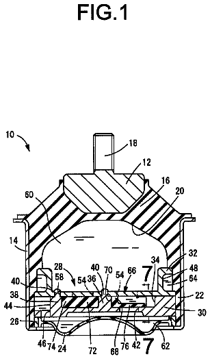
A first mode of the present invention provides a fluid-filled vibration damping device including a first mounting member and a second mounting member linked by a main rubber elastic body; a partition member disposed supported by the second mounting member and defining to one side of the partition member a pressure-receiving chamber whose wall is partially constituted by the main rubber elastic body, while defining to the other side of the partition member an equilibrium chamber whose wall is partially constituted by a flexible film, the pressure-receiving chamber and the equilibrium chamber being filled with a non-compressible fluid; and an orifice passage through which the pressure-receiving chamber and the equilibrium chamber communicate with one another; the device being characterized in that the partition member comprises an inner orifice member fitting inside an outer orifice member having a tubular portion with the members relatively displaceable in the axial direction; an orifice-defining window is provided on either one of two mating faces of an inside peripheral face of the tubular portion of the outer orifice member and an outside peripheral face of the inner orifice member; the orifice passage is defined utilizing a covered zone of the orifice-defining window, the zone being produced through partial covering of the orifice-defining window by the other of the outer orifice member and the inner orifice member; the covered zone of the orifice-defining window changes through relative displacement of the inner orifice member in the axial direction with respect to the outer orifice member; and fluid path length along the orifice passage between the opening thereof at the pressure-receiving chamber end and the opening thereof at the equilibrium chamber end changes in association with change of the covered zone of the orifice-defining window.
In the fluid-filled vibration damping device in accordance with the present mode, the length of the orifice passage is adjustable, so that tuning of the orifice passage may change according to the frequency of input vibration. For this reason, vibration damping based on resonance action etc. of fluid caused to flow through the orifice passage can be exhibited against several types of vibration having different frequencies.
Furthermore, passage length of the orifice passage is designed to change through relative displacement of the outer orifice member and the inner orifice member in the axial direction. For this reason, even where actuating force for bringing about this relative displacement of the outer orifice member and the inner orifice member is transmitted from outside the fluid chamber, it will be easier to effect sealing along the actuating force transmission path as compared to a construction in which passage length of the orifice passage is reset through relative rotation of the outer orifice member and the inner orifice member. Consequently, fluidtightness of the fluid chamber can be assured through a simple construction, and diminished vibration damping capability due to leakage of the sealed fluid can be avoided. Thus, the fluid-filled vibration damping device may be attained with excellent durability and reliability.
(Second Mode of the Invention)
A second mode of the invention provides a fluid-filled vibration damping device in accordance with the first mode wherein the orifice-defining window is helical in form extending in the circumferential direction while sloping in the axial direction.
In the fluid-filled vibration damping device in accordance with the present mode, sufficient passage length of the orifice passage can be efficiently ensured without the need to increase the size of the inner orifice member. For this reason, the tuning frequency of the orifice passage can be reset over a wider frequency range.
(Third Mode of the Invention)
A third mode of the invention provides a fluid-filled vibration damping device in accordance with the first or second mode wherein an orifice connection window extending in the circumferential direction is formed on either one of two mating faces selected from the inside peripheral face of the tubular portion of the outer orifice member and the outside peripheral face of the inner orifice member; the orifice connection window is sloped relative to the orifice-defining window; and the orifice passage communicates with either the pressure-receiving chamber or the equilibrium chamber through the intersection point of the orifice connection window and the orifice-defining window.
By forming the orifice connection window so as to extend in the circumferential direction on a slope relative in the axial direction to the orifice-defining window with their intersection point defining one opening of the orifice passage in this way, passage length of the orifice passage will be modifiable through linear relative displacement in the axial direction by the inner orifice member with respect to the outer orifice member. Further, because an opening of the orifice passage is defined by the intersection of the orifice-defining window and the orifice connection window, the cross sectional area of the opening on the side defined by the intersection can be set with a higher degree of accuracy according to intended tuning frequency, and vibration damping can be more efficiently attained.
(Fourth Mode of the Invention)
A fourth mode of the invention provides a fluid-filled vibration damping device in accordance with the third mode wherein either the orifice-defining window or the orifice connection window is helical in form extending in the circumferential direction while sloping in the axial direction; while the other of the orifice-defining window or the orifice connection window is annular in form extending in the circumferential direction without sloping.
By employing such a construction, the orifice-defining window and the orifice connection window can be sloped relatively in the axial direction, and change of the intersection of the orifice-defining window and the orifice connection window can be accomplished through relative displacement of the outer orifice member and the inner orifice member in the axial direction. Additionally, by giving either the orifice-defining window or the orifice connection window helical form, the other can be given simple annular form. Further, by giving either the orifice-defining window or the orifice connection window helical form while giving the other non-sloping annular form, the location of intersection of the orifice-defining window and the orifice connection window will be established through relative positioning of the outer orifice member and the inner orifice member in the axial direction, without the need for relative positioning of the outer orifice member and the inner orifice member in the circumferential direction. For this reason, the inner orifice member can easily fit inside the outer orifice member.
(Fifth Mode of the Invention)
A fifth mode of the invention provides a fluid-filled vibration damping device in accordance with the third mode wherein both the orifice-defining window and the orifice connection window are helical in form extending in the circumferential direction while sloping in the axial direction, with the orifice-defining window and the orifice connection window being sloped in mutually opposite directions.
By employing such a construction, the orifice-defining window and the orifice connection window are sloped relatively in the axial direction, and the intersection point location of the orifice-defining window and the orifice connection window can change through relative displacement of the outer orifice member and the inner orifice member in the axial direction. Additionally, because both the orifice-defining window and the orifice connection window slope in the axial direction with their direction of slope set to opposite directions, the orifice-defining window and the orifice connection window can be given large relative slope. As a result, the extent of movement of the intersection point location in the circumferential direction with respect to the extent of relative displacement of the outer orifice member and the inner orifice member in the axial direction will be fairly small, making it possible to tune the orifice passage with a higher degree of accuracy.
(Sixth Mode of the Invention)
A sixth mode of the invention provides a fluid-filled vibration damping device according to any of the third to fifth modes wherein the inner orifice member includes an inner tubular portion adapted to fit inside the tubular portion of the outer orifice member; and the orifice connection window is formed passing through a peripheral wall of the inner tubular portion.
In the fluid-filled vibration damping device in accordance with the present mode, by providing the inner orifice member with an inner tubular portion and forming the orifice connection window in the inner tubular portion, there can be devised an orifice connection window that extends in the circumferential direction.
(Seventh Mode of the Invention)
A seventh mode of the invention provides a fluid-filled vibration damping device according to any of the third to sixth modes wherein linking crosspieces that for reinforcement purposes link together the edges at the axial direction sides of the orifice connection window are provided at prescribed intervals in the circumferential direction of the orifice connection window.
In the fluid-filled vibration damping device in accordance with the present mode, it is possible to avoid lower strength of the inner orifice member in association with forming of the orifice connection window, and to attain ample durability. Additionally, where the orifice connection window has been formed so as to extend continuously about the entire circumference, this linking together of both sides of the orifice connection window by the linking crosspieces will allow the inner orifice member to be formed as a single member undivided by the orifice connection window, thus avoiding an increased number of parts and more complicated construction.
(Eighth Mode of the Invention)
An eighth mode of the invention provides a fluid-filled vibration damping device according to any of the first to seventh modes wherein the orifice-defining window is formed so as to open onto the outside peripheral face of the inner orifice member.
In the fluid-filled vibration damping device in accordance with the present mode, by forming the orifice-defining window in the inner orifice member which fits inside the outer orifice member, an orifice passage of relatively short path length can be formed with good space efficiency. Additionally, by forming in the large-diameter outer orifice member a path that is separate from the orifice passage, it is possible to appositionally provide a fluid passage tuned to lower frequencies and the orifice passage with good space efficiency.
(Ninth Mode of the Invention)
A ninth mode of the invention provides a fluid-filled vibration damping device according to any of the first to seventh modes wherein the orifice-defining window is formed so as to open onto the inside peripheral face of the outer orifice member.
In the fluid-filled vibration damping device in accordance with the present mode, by forming the orifice-defining window in the large-diameter outer orifice member, an orifice passage of extended path length can be formed with good space efficiency, and the orifice passage can be tuned to a lower frequency.
(Tenth Mode of the Invention)
A tenth mode of the invention provides a fluid-filled vibration damping device in accordance with the ninth mode wherein the outer orifice member is designed with bottomed tubular shape opening either towards the pressure-receiving chamber end or towards the equilibrium chamber end, with the orifice-defining window opening onto the inside peripheral face thereof; and the inner orifice member fits inside the outer orifice member and is positioned so as to partition a peripheral interior of the outer orifice member into a basal end and an open end.
In the fluid-filled vibration damping device in accordance with the present mode, the basal end of the peripheral interior of the outer orifice member defines to one side of the inner orifice member a dead-end liquid chamber which is substantially sealed off, thereby restricting the inflow and outflow of fluid. Thus, a path having prescribed cross sectional area is defined not only in the orifice-defining window in a zone thereof covered by the inner orifice member, but is defined also in a zone situated closer towards the basal end than the section that is covered by the inner orifice member. For this reason, it will be possible to ensure an orifice passage of sufficient length while maintaining a small axial dimension for the inner orifice member, so that lighter weight and smaller size in the axial direction can be achieved. Also, by employing a bottomed tubular shape for the outer orifice member, strength can be ensured more advantageously than where an annular form is employed. The open end of the peripheral interior of the outer orifice member to the other side of the inner orifice member opens into the pressure-receiving chamber or the equilibrium chamber, so that the orifice passage communicates with the pressure-receiving chamber or the equilibrium chamber by a zone situated towards the open end in the orifice-defining window.
(Eleventh Mode of the Invention)
An eleventh mode of the invention provides a fluid-filled vibration damping device in accordance with the tenth mode wherein the orifice-defining window is sloped in the axial direction and extends in the circumferential direction; and the inner orifice member is of flat plate shape, with the outside peripheral face of the inner orifice member being superposed against the inside peripheral face of the outer orifice member.
In the fluid-filled vibration damping device in accordance with the present mode, the inner orifice member is given flat plate shape extending approximately in the axis-perpendicular direction so that the inner orifice member can be reduced in weight while ensuring sufficient passage length of the orifice passage; and the axial dimension of the inner orifice member can be made smaller so that the fluid-filled vibration damping device as a whole is more compact in the axial direction.
(Twelfth Mode of the Invention)
A twelfth mode of the invention provides a fluid-filled vibration damping device according to any of the first to eleventh modes wherein an actuator shaft attached at one end thereof to the inner orifice member passes through the flexible film and extends to the outside of the equilibrium chamber, while the other end of the actuator shaft is attached to an actuator that is situated outside the equilibrium chamber; and an actuating force of the actuator is exerted on the inner orifice member through an agency of the actuator shaft to bring about relative displacement of the inner orifice member in the axial direction with respect to the outer orifice member.
In the fluid-filled vibration damping device in accordance with the present mode, a mechanism for adjusting the length of the orifice passage can be realized through displacement of the inner orifice member in the axial direction. For this reason, in a construction where the actuator for actuating the inner orifice member is situated outside the equilibrium chamber, there can be employed a structure whereby the actuator shaft for transmitting actuating force of the actuator to the inner orifice member is made to describe reciprocating motion in the axial direction. As a result, sealing of the actuator shaft passage zone in the flexible film can be effected by a simple construction.
(Thirteenth Mode of the Invention)
A thirteenth mode of the invention provides a fluid-filled vibration damping device according to any of the first to twelfth modes wherein axial direction guiding means is provided between the outer orifice member and the inner orifice member, for controlling relative displacement thereof in the axis-perpendicular direction and for guiding relative displacement in the axial direction.
In the fluid-filled vibration damping device in accordance with the present mode, the inside peripheral face of the outer orifice member and the outside peripheral face of the inner orifice member can be prevented from being forcibly pushed against one another due to relative displacement of the outer orifice member and the inner orifice member in the axis-perpendicular direction, thus preventing a situation where relative displacement of the inner orifice member with respect to the outer orifice member in the axial direction is hampered by frictional force. Further, because relative displacement of the inner orifice member with respect to the outer orifice member in the axial direction is guided by axial direction guiding means, relative displacement in the axial direction can take place more smoothly.
(Fourteenth Mode of the Invention)
A fourteenth mode of the invention provides a fluid-filled vibration damping device in accordance with the thirteenth mode wherein the actuator for bringing about relative displacement of the inner orifice member with respect to the outer orifice member is situated at a first axial end of the inner orifice member, and the axial direction guiding means is provided at the other axial end thereof.
In the fluid-filled vibration damping device in accordance with the present mode, as compared to the case where axial direction guiding means is provided by utilizing the inside peripheral face of the outer orifice member and the outside peripheral face of the inner orifice member, situations such as sticking by the orifice-defining window can be prevented. Thus, relative displacement of the inner orifice member with respect to the outer orifice member can take place more smoothly. Such axial direction guiding means may be achieved, for example, by employing an inverted, approximately bottomed round tubular shape for the outer orifice member and providing a guide tube on the upper base wall thereof, while providing the inner orifice member with a guide projection that projects out to one end in the axial direction, and inserting the guide projection into the guide tube so as to be slidable therein in the axial direction.
(Fifteenth Mode of the Invention)
A fifteenth mode of the invention provides a fluid-filled vibration damping device according to any of the first to fourteenth modes wherein liquid pressure absorbing means is disposed in the partition member in the wall thereof that partitions the pressure-receiving chamber from the equilibrium chamber.
In the fluid-filled vibration damping device in accordance with the present mode, vibration damping is realized by utilizing liquid pressure absorbing action produced by the liquid pressure absorbing means based on tiny displacement and tiny deformation, so that further enhanced vibration damping capabilities may be achieved. Moreover, as the liquid pressure absorbing means is situated at a location away from the fluid path through the orifice passage, the liquid pressure absorbing means will provide effective vibration damping of vibration of frequencies outside the particular tuning frequency of the orifice passage.
(Sixteenth Mode of the Invention)
A sixteenth mode of the invention provides a fluid-filled vibration damping device according to any of the first to fifteenth modes wherein relative displacement of the outer orifice member and the inner orifice member in the axial direction is brought about by an actuator furnished with a pulse motor and a motion conversion mechanism adapted to convert rotational actuating force of a rotating shaft of the pulse motor to reciprocating actuating force in an axial direction.
By employing, as the actuator for relative displacement of the outer orifice member and the inner orifice member, a pulse motor (stepping motor) whose actuator shaft is controlled so as to rotate at prescribed rotation increments, the relative axial position of the outer orifice member and the inner orifice member can be set correctly through control of pulse count.
(Seventeenth Mode of the Invention)
A seventeenth mode of the invention provides a fluid-filled vibration damping device in accordance with the sixteenth mode wherein the device is implemented in an engine mount; and the required step number: .DELTA.y.sub.i, of the actuator shaft of the pulse motor corresponding to a particular engine speed is calculated using an equation below, with the actuator being controlled on the basis of a calculation result: .DELTA.y.sub.i=y.sub.i+1-y.sub.i y.sub.i=a.times.(x.sub.i/60).times.n+b x.sub.i denotes engine rpm y.sub.i denotes actuator shaft step number depending on an engine speed: x.sub.i n is a multiplying factor determined according to engine model a and b are constants determined according to vehicle characteristics.
By controlling the number of actuation steps of the pulse motor through computation of a differential of the number of actuation steps of the pulse motor, it is possible to continuously reset the axial position of the inner orifice member without the need to detect the axial position of the inner orifice member with a position sensor or the like.
(Eighteenth Mode of the Invention)
An eighteenth mode of the invention provides a fluid-filled vibration damping device according to any of the first to seventeenth modes wherein a fluid passage that connects the pressure-receiving chamber with the equilibrium chamber is formed in the partition member; and a tuning frequency of the fluid passage is set to a lower frequency than the orifice passage.
In the fluid-filled vibration damping device in accordance with the present mode, by providing a fluid passage tuned to a lower frequency than the tuning range settable for the orifice passage, the intended vibration damping can be produced against vibration over a wider frequency range.
(Nineteenth Mode of the Invention)
A nineteenth mode of the invention provides a fluid-filled vibration damping device in accordance with the eighteenth mode wherein the fluid passage assumes a continuous communicating state.
Specifically, because the tuning frequency of the fluid passage has been set to a lower frequency than the tuning frequency of the orifice passage, despite a design wherein the fluid passage is maintained in a continuous communicating state, at times of input of vibration of frequency corresponding to the tuning frequency of the orifice passage the fluid passage will assume a substantially clogged state due to antiresonance action of the fluid. For this reason, at times of input of vibration having the frequency mentioned above, fluid flow through the fluid passage will be limited, so fluid flow through the orifice passage will be effectively produced so that the intended vibration damping is effectively achieved. Moreover, by dispensing with a structure for switching the fluid passage between communicating and blocked states, fewer parts are required, and the fluid-filled vibration damping device can be made more compact in size and lighter in weight.
(Twentieth Mode of the Invention)
A twentieth mode of the invention provides a fluid-filled vibration damping device in accordance with the eighteenth or nineteenth mode wherein the fluid passage is formed in the outer orifice member.
In the fluid-filled vibration damping device in accordance with the present mode, by forming the fluid passage, which is tuned to a lower frequency, in the large-diameter outer orifice member, it is possible to efficiently establish a longer passage length for the fluid passage. The fluid passage can thus be formed with a high degree of freedom in tuning, without a corresponding increase in size of the partition member.
Also, by forming the fluid passage in the outer orifice member while forming the orifice passage in the inner orifice member, there can be efficiently ensured space for forming the fluid passage and the orifice passage. It is accordingly possible to achieve a fluid-filled vibration damping device that while compact in size exhibits outstanding vibration damping performance owing to concomitant provision of a fluid passage and an orifice passage.
(Twenty-First Mode of the Invention)
A twenty-first mode of the invention provides a fluid-filled vibration damping device according to any of the eighteenth through twentieth modes wherein flow regulating means for restricting fluid flow through the orifice passage is situated on the fluid path through the orifice passage.
By so doing, at times of input of vibration of the frequency range to which the fluid passage has been tuned, the flow rate restricting means will restrict fluid flow through the orifice passage, and vibration damping will be produced efficiently on the basis of flow action of fluid in the fluid passage. On the other hand, at times of input of vibration in the frequency range to which the orifice passage has been tuned, the flow rate restricting means, on the basis of deformation and/or displacement thereof, will permit fluid flow through the orifice passage, and vibration damping will be produced on the basis of flow action of fluid in the orifice passage. For this reason, both vibration damping on the part of the fluid passage and vibration damping on the part of the orifice passage will be effectively obtained so as to attain further improvement in vibration damping capabilities.
(Twenty-Second Mode of the Invention)
A twenty-second mode of the invention provides a fluid-filled vibration damping device according to any of the eighteenth through twenty-first modes wherein the orifice passage is blocked by bringing the inner orifice member to a specific position in the axial direction with respect to the outer orifice member.
In the fluid-filled vibration damping device in accordance with the present mode, it is possible to block the orifice passage by bringing about relative displacement of the inner orifice member to a specific position with respect to the outer orifice member. For this reason, at times of input of low-frequency vibration, the orifice passage will become blocked so as to efficiently give rise to fluid flow through the fluid passage and more effectively produce the intended vibration damping.
(Twenty-Third Mode of the Invention)
A twenty-third mode of the invention provides a fluid-filled vibration damping device in accordance with the twenty-second mode wherein a cover part is provided to the other of the outer orifice member and the inner orifice member; and in the orifice passage the opening that leads either to the pressure-receiving chamber end or to the equilibrium chamber end is covered by the cover part through relative displacement of the outer orifice member and the inner orifice member in the axial direction.
In the fluid-filled vibration damping device in accordance with the present mode, it is possible to bring about blocking of the orifice passage through relative displacement of the inner orifice member in the axial direction with respect to the outer orifice member. For this reason, fluid flow through the fluid passage can be produced efficiently through blocking of the orifice passage, and vibration damping based on fluid flow action arising in the fluid passage can be obtained more advantageously.
The opening of the orifice passage may be designed to be blocked through positioning of the cover part in intimate contact against the rim of the opening of the orifice passage, or designed to be substantially blocked through flow friction of fluid produced by positioning the cover part in opposition to the opening of the orifice passage with a tiny gap between them.
(Twenty-Fourth Mode of the Invention)
A twenty-fourth mode of the invention provides a control method for the fluid-filled vibration damping device in accordance with the twenty-second mode or twenty-third mode where employed as an automotive engine mount, the method being designed to control the vibration damping characteristics of the automotive engine mount through actuation control of the actuator adapted to bring about relative displacement of the inner orifice member in the axial direction with respect to the outer orifice member; wherein using driving/idling determining means adapted to determine if an automobile is moving or idling and speed measuring means for measuring engine speed of the automobile, in the event of a decision by the driving/idling determining means that the automobile is moving, the orifice passage will be blocked to allow fluid flow through the fluid passage, whereas in the event of a decision by the driving/idling determining means that the automobile is idling, the orifice passage will be opened, and a relative position of the inner orifice member with respect to the outer orifice member in the axial direction will undergo controlled modification depending on the engine speed that was measured by the speed measuring means, so as to shorten a passage length of the orifice passage in response to higher engine speed.
According to the automotive engine mount control method in accordance with the present embodiment, it is possible for vibration damping to be produced efficiently against input vibration over a wider frequency range, making it possible to achieve advanced vibration damping capabilities.
Specifically, first, by switching the orifice passage to the communicating or blocked state based on the decision by the driving/idling determining means, effective vibration damping is produced both against the low-frequency vibration that tends to be a problem when the automobile moving, and against the midrange- to high-frequency vibration that tends to be a problem when the automobile is idling. That is, with the automobile at a stop, the orifice passage will open to give rise to fluid flow through the orifice passage, whereby the intended vibration damping (low dynamic spring action) can be produced against the midrange- to high-frequency vibration such as idling vibration that tends to be a problem when the automobile is at a stop. When the automobile is moving on the other hand, the orifice passage will be blocked to give rise to fluid flow through the fluid passage which has been tuned to a lower frequency than the orifice passage, whereby the intended vibration damping (high attenuating action) can be produced against the low-frequency vibration such as engine shake that tends to be a problem when moving.
Further, in the event of a decision by the driving/idling determining means that the automobile is idling, the passage length of the orifice passage which has assumed the communicating state will be adjusted on the basis of the engine speed measurement by the speed measuring means. Specifically, for example with the automobile at a stop, if engine speed should increase in association with startup of the engine or with use of the air conditioning, the frequency of the vibration input from the power unit will shift towards the high-frequency band. In response, the passage length of the orifice passage will be reset to shorter length so that the tuning frequency of the orifice passage can be adjusted to the high-frequency band in response to this change in frequency of the input vibration, so that vibration damping can be obtained efficiently based on fluid flow through the orifice passage.
(Twenty-Fifth Mode of the Invention)
A twenty-fifth mode of the invention provides an automotive engine mount control method in accordance with the twenty-fourth mode wherein a pulse motor is employed as the power source of the actuator, and the relative position of the inner orifice member with respect to the outer orifice member in the axial direction is controlled through control of the pulse motor.
In the automotive engine mount control method in accordance with the present embodiment, by controlling the number of pulses applied to the motor, the relative position of the inner orifice member with respect to the outer orifice member in the axial direction can be controlled with high accuracy, without the need for a feedback circuit or other complicated control circuitry. Consequently, it is possible to provide an automotive engine mount by which advanced vibration damping is attained at low cost and with simple construction.
(Twenty-Sixth Mode of the Invention)
The description continues in the full USPTO document.
 Lapsed, fee not paid11 drawings