 Lapsed, fee not paid12 drawings
Telecom & Networks · US 8,553,583 B2
Leaky ethernet trees
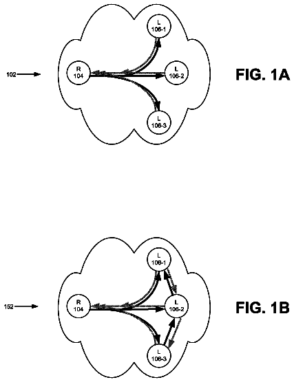
A network device may receive an Ethernet frame from a first leaf user-to-network (UNI) interface in a tree.
US 8,553,595 B2 · Assignee: Qualcomm Incorporated · Inventors: Laroia; Rajiv et al.
Sheet 1 of 14 from the published document. All sheets in the USPTO PDF
Methods of using superposition coding in a communications systems, e.g., a multi-user communications system. Superposition coding in accordance with the invention occurs in the case of an uplink by transmissions of different wireless terminals transmitting using the same communications resource, e.g., simultaneously transmitting using the same frequencies. The signals combine in the communications channel resulting in one transmission being superimposed on the other transmission. The device, e.g., base station, receiving the superimposed signals uses superposition decoding techniques to recover both signals. To obtain the benefit of the superposition, assignments of channel segments to multiple wireless terminals is controlled by the base station and/or transmission power levels are controlled by on or more wireless terminals sharing the same uplink communications resource, e.g., time slot, to make sure that the received signals from the different devices will have different received power levels making superposition decoding possible.
Superposition coding in communications systems shall be described. Multi-user communication systems involve several transmitters and receivers communicating with each other and may use one or more communications methods. In general, multi-user communication methods may be categorized into one of two scenarios: (a) A single transmitter communicating with several receivers, commonly referred to as a broadcast communications method, and (b) Several transmitters communicating to a common receiver, which is commonly referred to as a multiple-access communications method. The broadcast communications method is commonly known in the communications and information theory literature as the `broadcast channel`. The `broadcast channel` refers to each of the physical communication channels between the transmitter and the multiple receivers as well as the communication resources used by the transmitt
1 of 14 drawing sheets so far from the published document, cropped to the drawing. Every sheet is in the USPTO PDF.
What the patent claimed, word for word. All of it is now free to use.
The present invention is directed to improved methods of codling and transmitting in a wireless communications system, and more specifically to improved methods using controlled superposition coding suitable for use in, e.g., a multi-user communications system.
Superposition coding in communications systems shall be described. Multi-user communication systems involve several transmitters and receivers communicating with each other and may use one or more communications methods. In general, multi-user communication methods may be categorized into one of two scenarios: (a) A single transmitter communicating with several receivers, commonly referred to as a broadcast communications method, and (b) Several transmitters communicating to a common receiver, which is commonly referred to as a multiple-access communications method.
The broadcast communications method is commonly known in the communications and information theory literature as the `broadcast channel`. The `broadcast channel` refers to each of the physical communication channels between the transmitter and the multiple receivers as well as the communication resources used by the transmitter to communicate. Similarly, the multiple-access communications method is widely known as the `multiple-access channel`. The `multiple-access channel` refers to the physical communication channels between the multiple transmitters and the common receiver, along with the communication resources used by the transmitters. The broadcast communications method is frequently used to implement the downlink communication channel in a typical cellular wireless system while the uplink channel in such a system is commonly implemented using the multiple-access communications method.
The transmission resource in a multi-user communication system can generally be represented in time, frequency or code space. Information theory suggests that the capacity of the system can be increased over other communication techniques in both the broadcast scenario and the multiple-access scenario. In particular, by transmitting to multiple receivers simultaneously in the case of the broadcast communications method, or by allowing multiple transmitters to transmit simultaneously in the case of the multiple-access communications method, over the same transmission resource, the capacity of the system can be increased over other communication techniques. In the case of the broadcast communications method, the technique used to transmit simultaneously to multiple users over the same transmission resource is also known as `superposition coding`.
The advantages of superposition coding will be apparent in view of the following discussion of transmission techniques for the broadcast communications method. Consider a single transmitter communicating with two receivers, whose channels can be described by ambient Gaussian noise levels of N.sub.1 and N.sub.2, with N.sub.1<N.sub.2, i.e., the first receiver operates over a stronger channel than the second receiver. Assume that the communication resources available to the transmitter are a total bandwidth of W, and a total power of P. The transmitter may employ several strategies to communicate with the receivers. FIG. 1 is a graph 100 plotting the achievable rates in a broadcast channel for a first and second user for three different transmission strategies. Vertical axis 102 represents the rate for the stronger receiver, while horizontal axis 104 represents the rate for the weaker receiver. Line 106 shows achievable rates for a time division multiplexing (TDM) strategy. Line 108 shows achievable rates for a frequency division multiplexing (FDM) strategy. Line 110 shows maximum capacity achievable rates.
First, consider the strategy where the transmitter multiplexes between the two receivers in time, allocating all its resources to one receiver at a time. If the fraction of time spent communicating with the first (stronger) receiver is denoted by .alpha., it may be shown that the achievable rates for the two users satisfy the following equations.
.ltoreq..alpha..times..times..times..times..function..times..ltoreq..alph- a..times..times..times..function. ##EQU00001##
As the fraction of time spent serving the first user, .alpha., varies, the rates achieved by the above equations are represented with the straight solid line 106 corresponding to `TDM` as shown in FIG. 1.
Now consider a different transmission strategy where the transmitter allocates a certain fraction of the bandwidth, .beta., and a fraction of the available power, .gamma., to the first user. The second user gets the remaining fractions of bandwidth and power. Having allocated these fractions, the transmitter communicates with the two receivers simultaneously. Under this transmission strategy, the rate region can be characterized by the following equations.
.ltoreq..beta..times..times..times..times..function..alpha..times..times.- .times..ltoreq..beta..times..times..times..function..alpha..times. ##EQU00002##
The rates achieved by the above equations are visualized intuitively from the convex dashed curve line 108 corresponding to `FDM` as shown in FIG. 1. It is evident that the strategy of dividing the available power and bandwidth between the two users in an appropriate manner outperforms the time-division partition of resources. However, the second strategy, is not yet the optimal one.
The supremum of the rate regions achievable under all transmission strategies is the broadcast capacity region. For the Gaussian case, this region is characterized by the equations
.ltoreq..times..times..function..alpha..times..times..times..ltoreq..time- s..times..function..alpha..times..alpha..times..times. ##EQU00003## and is indicated by the dash/dot curve line 110 corresponding to `CAPACITY` as shown in FIG. 1.
It was shown by Thomas Cover in T. M. Cover, Broadcast Channels, IEEE Transactions on Information Theory, IT-18 (1):2 14, 1972, that a communication technique called superposition coding could achieve this capacity region. In this technique, the signals to different users are transmitted with different powers in the same transmission resource and superposed on each other. The gains achievable through superposition coding surpass any other communication technique that requires splitting of the transmission resource among different users.
The basic concept of superposition coding is illustrated in FIG. 2. FIG. 2 is a graph 200 illustrating a high power QPSK signal and a low power QPSK signal superposed on the high power QPSK signal. Vertical axis 202 represents Q-component signal strength while horizontal axis 204 represents P-component signal strength. While the example of FIG. 2 assumes QPSK modulation, the choice of modulation sets is not restrictive, and, in general, other modulation sets may be alternatively used. Also, the example FIG. 2 is sketched out for an exemplary case of two users, while the concept may he generalized and applied in a straightforward manner to multiple users. Assume that the transmitter has a total transmit power budget P. Suppose that the first receiver, referred to as `weaker receiver`, sees larger channel noise and the second receiver, referred to as `stronger receiver`, sees smaller channel noise. Four circles 206, filled in with a pattern, represent the QPSK constellation points to be transmitted at high power (better protected), (1-.alpha.)P, to the weaker receiver. Meanwhile, additional information is convened to the stronger receiver at low power (less protected), .alpha.P, also using a QPSK constellation. In FIG. 2, arrow 208 of magnitude ((1-.alpha.)P) provides an indication of the high transmission power, awhile arrow 210 (.alpha.P) provides an indication of the low transmission power. The actually transmitted symbols, which combine both the high power and low power signals, are represented as blank circles 212 in the figure. A key concept that this illustration conveys is that the transmitter communicates to both users simultaneously using the same transmission resource.
The receiver strategy is straightforward. The weaker receiver sees the high power QPSK constellation with a low-power signal superposed on it. The SNR experienced by the weaker receiver may be insufficient to resolve the low-power signal, so the low power signal appears as noise and slightly degrades the SNR when the weaker receiver decodes the high power signal. On the other hand, the SNR experienced by the stronger receiver is sufficient to resolve both the high power and low power QPSK constellation points. The stronger receiver's strategy is to decode the high-power points (which are intended for the weaker receiver) first, remove their contribution from the composite signal, and then decode the low-power signal.
Based upon the above discussion, it should be appreciated that there is a need for variations and/or adaptations of the superposition coding concept which could be used to more effectively utilize air link resources in broadcast and/or multiple-access communications systems. In a wireless communications system, with multiple users, at any given time, different channel qualities will exist for the various users. Methods and apparatus that characterize the different receivers and transmitters as weaker/stronger on a relative basis with respect to one another and allow for these relative classifications to change over time may also be useful. Methods and apparatus of scheduling and power control that opportunistically utilize these differences and apply superposition coding methods could increase system capacity. New implementations using superposition coding methods may need methods to convey information between transmitters(s) and receiver(s) concerning the superposition coding, e.g., such as the temporary weaker/stronger assignment information. Methods of communicating such information that minimize overhead, where possible, and/or combine or link temporary assignment designations between multiple Communication channel segments, e.g., an assignment channel segment and a traffic channel segment, would be advantageous.
The present invention is directed to new and novel methods of using superposition coding in a communications systems, e.g., a multi-user communications system. Superposition coding occurs in a downlink and/or an uplink. Superposition coding in accordance with the invention occurs in the case of the downlink by transmissions to different wireless terminals from a base station using the same communications resource, e.g., simultaneously with the same frequencies. Superposition coding in accordance with the invention occurs in the case of the uplink by transmissions from different wireless terminals to a base station using the same communications resource. In the uplink case, the signals combine in the communications channel resulting in one transmission being superimposed on the other transmission. The device, e.g., base station, receiving the superimposed signals uses superposition decoding techniques to recover both signals. To obtain the benefit of the superposition, assignments of channel segments to multiple wireless terminals is controlled by the base station. Moreover, in the downlink case, the transmission power levels are controlled by the base station so that the received power levels are very different to facilitate superposition decoding. In the uplink case, the transmission pouter levels are controlled by the wireless terminals sharing the same uplink communications resource, e.g., time slot and frequency, to make sure that the received signals from the different devices at the base station will have different received power levels facilitating superposition decoding.
In various embodiments of the present invention, the base station maintains information regarding the quality of the communications channels between individual wireless terminals and the base station. A communications channel segment is assigned to two or more wireless terminals having at least a minimum difference, e.g., a 3, 5 or 10 dB difference, in the quality of their communications channels from the base station in the downlink case or communications channels to the base station in the uplink case. Channel assignments are transmitted to wireless terminals which are to share a traffic channel segment. The assignment conveys which wireless terminals are to simultaneously use a communications channel segment and, in addition, which of the assigned devices is to transmit (in the uplink case) or receive (in the downlink case) the strong or weak signal. Assignment messages may be transmitted as superimposed signals.
For the sake of simplifying the description, this document assumes that to signals are superimposed to form a superposition coding signal. However, more than two signals can be superimposed. The invention is applicable to the cases where more than two signals are superimposed to form a superposition coding signal.
Hence, the two signals of a superposition coding signal are respectively called the strong signal and the weak signal, where the strong signal is the one with high received power and the weak signal is the one with low received power. When two wireless terminals share the same communications resource, the one with better channel condition is called the stronger user and the one with worse channel condition is called the weaker user. In some embodiments, a given wireless terminal may be the strong user when it shares the resource with another wireless terminal, and be the weaker user when it shares the resource with a third wireless terminal.
In many uplink cases, the stronger user will be assigned to operate transmitting the signal which will be received by the base station as the strong signal and the weaker user will normally be assigned to operate transmitting the signal which will be received by the base station as the weak signal. This avoids generating excessive interference to other base stations or requiring excessive peak transmission power from the wireless terminal. In those cases, the stronger user is also called stronger transmitter and the weaker user is also called weaker transmitter.
In many downlink cases, the stronger user will be assigned to operate receiving the weak signal and the weaker user will normally be assigned to operate receiving the strong signal. This helps to improve the link reliability of the weaker user while not wasting power to the stronger user. In those cases, the stronger user is also called stronger receiver and the weaker user is also called weaker receiver.
Channel assignments transmitted to wireless terminals which are to share a traffic channel segment may also be made using superposition coding. Note that channel assignments are generally made by the base station and transmitted in the downlink. This, the assignment sent to the stronger user is transmitted with the weak signal and the assignment sent to the weaker user is transmitted with the strong signal. Hence, if a wireless terminal realizes that the assignment for it comes from the strong signal, e.g., its terminal identifier is transmitted by the strong signal, the wireless terminal knows that it is considered by the base station as the weaker user, i.e., the weaker transmitter in the case where the wireless terminal is assigned an uplink traffic channel or the weaker receiver in the case where the wireless terminal is assigned a downlink traffic channel. Similarly, if a wireless terminal realizes that the assignment for it comes from the weak signal, the wireless terminal knows that it is considered by the base station as the stronger user, i.e., the stronger transmitter where the wireless terminal is assigned an uplink traffic channel or the stronger receiver where the wireless terminal is assigned a downlink traffic channel.
In accordance with the present invention, superposition coding can be used in an opportunistic manner. That is, superposition coding may be used when wireless terminals with sufficiently different channel conditions are available to be paired to share a communications channel segment. In cases where a sufficient difference in received power levels may not be achieved, e.g., due to an insufficient different in channel conditions between devices or insufficient transmission power capabilities, wireless terminals are not scheduled to share a transmission segment. Thus, superposition is used in transmission slots where it is likely to produce reliable results due to sufficient received power level differences but not in cases here it is likely to be unreliable.
Numerous additional features, benefits and advantages of the present invention will be apparent in view of the detailed description which follows.
FIG. 1 shows a graph illustrating achievable rates in a broadcast channel for a first user with a stronger receiver and a second user with a weaker receiver under three different transmission strategies.
FIG. 2 illustrates an example of superposition coding with QPSK modulation.
FIG. 3 illustrates an exemplary communications systems implementing the apparatus and methods of the present invention.
FIG. 4 illustrates an exemplary base station implemented in accordance with the present invention.
FIG. 5 illustrates an exemplary wireless terminal implemented in accordance with the present invention.
FIG. 6 illustrates exemplary traffic channel segments.
FIG. 7 illustrates exemplary assignment and traffic segments.
FIG. 8 illustrates exemplary downlink traffic segments and exemplary uplink acknowledgement segments.
FIG. 9 illustrates an exemplary communications system implemented in accordance with the present invention.
FIG. 10 illustrates superposition coding in a multiple-access channel in accordance with the present invention.
FIG. 11 illustrates superposition coding used in broadcast assignment and broadcast traffic channels, in accordance with the present invention.
FIG. 12 illustrates superposition coding used in broadcast assignment and multiple-access traffic channels, in accordance with the present invention.
FIG. 13 illustrates superposition coding used in broadcast traffic and multiple-access acknowledgement channels, in accordance with the present invention.
FIG. 14 illustrates superposition coding used in multiple-access traffic and broadcast acknowledgement channels, in accordance with the present invention.
FIG. 15 illustrates an exemplary embodiment of the present invention using superposition coding on a common control channel.
FIG. 16 illustrates exemplary uplink signals on the same channel segment and is used to illustrate an exemplary embodiment of received power targets, in accordance with the present invention.
FIG. 17 is a flow chart illustrating the steps of an exemplary method implemented by a base station in one exemplary embodiment.
FIG. 18 is a flow chart illustrating the steps of all exemplary method implemented by a wireless terminal in one exemplary embodiment.
As discussed above, the present invention is directed to new and novel methods of using superposition coding in a communications systems, e.g., a multi-user communications system. Superposition coding occurs in a downlink and/or an uplink. Superposition coding in accordance with the invention occurs in the case of the downlink by transmissions to different wireless terminals from a base station using the same communications resource, e.g., simultaneously with the same frequencies. Superposition coding in accordance with the invention occurs in the case of the uplink by transmissions from different wireless terminals to a base station using the same communications resource. In the uplink case, the signals combine in the communications channel resulting in one transmission being superimposed on the other transmission. The device, e.g., base station, receiving the superimposed signals uses superposition decoding techniques to recover both signals. To obtain the benefit of the superposition, assignments of channel segments to multiple wireless terminals is controlled by the base station. Moreover, in the downlink case, the transmission power levels are controlled by the base station so that the received power levels are very different to facilitate superposition decoding. In the uplink case, the transmission power levels are controlled by the wireless terminals sharing the same uplink communications resource, e.g., time slot, to make sure that the received signals from the different devices at the base station will have different received power levels facilitating superposition decoding.
FIG. 3 illustrates an exemplary wireless communications system 300 implemented in accordance with and using the methods of the present invention. Exemplary wireless communications system 300 opportunistically uses controlled superposition coding methods on uplink channels and downlink channels in accordance with the present invention. Exemplary wireless communications system 300 is a spread spectrum OFDM (orthogonal frequency division multiplexing) multiple-access system. While an exemplary OFDM wireless communications system is used in this application for purposes of explaining the invention, the invention is broader in scope than the example, and the invention can be applied in many other communication systems, e.g. a CDMA wireless communications system, as well where controlled superposition coding is employed.
System 300 includes a plurality of cells: cell 1 302, cell M 304. Each cell (cell 1 302, cell M 304) includes a base station (BS), (BS 1 306, BS M 308), respectively, and represents the wireless coverage area of the base station. BS 1 306 is coupled to a plurality of end nodes, (EN
310, EN(X) 312) via wireless links (314, 316), respectively. BS M 308 is coupled to a plurality of end nodes, (EN(1') 318, EN(X') 320) via wireless links (322, 324), respectively. The end nodes 310, 312, 318, 320 may be mobile and/or stationary wireless communications devices and are referred to as wireless terminals (WTs). Mobile WTs arc sometimes referred to as mobile nodes (MNs). MNs may move throughout system 300. BS 1 306 and BS M 308 are coupled to network node 326 via network links 328, 330, respectively. Network node 326 is coupled to other network nodes and the Internet via network link 332. Network links 328, 330, 332 may be, e.g., fiber optic cables.
FIG. 4 is an illustration of an exemplary base station 400 implemented in accordance with the invention. Exemplary base station 400 may be a more detailed representation of any of the base stations 306, 308 of FIG. 3. Base station 400 includes a receiver 402, a transmitter 406, a processor 410, an I/O interface 412, and a memory 414 coupled together via bus 416 over which the various elements may interchange data and information.
The receiver 402 is coupled to an antenna 404 through which base station 400 may receive uplink signals from a plurality of wireless terminals (WTs) 500 (See FIG. 5). Such uplink signals may include uplink traffic signals transmitted by different wireless terminals 500 on the same traffic segment which may superpose in the air and/or acknowledgment signals transmitted by different wireless terminals on the same acknowledgement segment which may superpose in the air, in accordance with the invention. Receiver 402 includes a plurality of demodulation modules, demodulation module 1 418, demodulation module N 420. In some embodiments, the demodulation modules 418, 420 may be part of a decoder module. The demodulation modules 418, 420 are coupled together. Demodulation module 1 418 malt perform a first demodulation on a received superposed signal recovering a high power or highly protected signal. The demodulated information may be forwarded from demodulation module 1 418 to demodulation module N 420. Demodulation module N 420 may remove the high power or highly protected signal from the received superposed signal, and then demodulate the low power or less protected signal. In some embodiments, separate receivers 402 and/or separate antennas 404 may be used, e.g.; a first receiver for the high (received) power or highly protected uplink signals and a second receiver for the low (received) power or low protection uplink signals.
Transmitter 406 is coupled to an antenna 408 through which base station 400 may transmit downlink signals to a plurality of wireless terminals 500. Such downlink signals may include superposed signals, e.g., a composite of two or more signals on the same channel segment, each signal of the composite at a different transmission power level, and each signal intended for a different wireless terminal. Superposed downlink signals may be opportunistically transmitted on assignment segments, on downlink traffic signals, and/or on acknowledgement segments, in accordance with the invention. Transmitter 406 includes a plurality of modulation modules, modulation module 1 422, modulation module N 424, and a superposition module 426. Modulation module 1 422 may modulate a first set of information, e.g., into a high power or highly protected signal, and modulation module N 424 may modulate a second set of information into a low power or low protection signal. Superposition module 426 combines the high power or highly protected signal with the low power or low protection signal such that a composite signal may be generated and transmitted on the same downlink segment. In some embodiments, multiple transmitters 406 and/or multiple antennas 408 may be used, e.g., a first transmitter for the high powered or highly protected downlink signals and a second transmitter for the low powered or low protection downlink signals.
I/O interface 412 is an interface providing connectivity of the base station 400 to other network nodes, e.g., other base stations, AAA server nodes, etc., and to the Internet. Memory 414 includes routines 428 and data/information 430. Processor 410, e.g., a CPU, executes the routines 428 and uses the data/information 430 in memory 414 to operate the base station 400 in accordance with the methods of the present invention.
Routines 428 include communications routines 432 and base station control routines 434. Base station control routines 434 include a scheduler module 436, wireless terminal power control routines 438, transmit power control routines 440, and signaling routines 442. Scheduler 436 includes a downlink scheduling module 446, an uplink scheduling module 448, and a relative user strength matching module 450. WT transmit power control routine 438 includes a received power target module 452.
Data/Information 430 includes data 454, wireless terminal data/information 456, system information 458, downlink assignment messages 460, downlink traffic channel messages 462, received acknowledgement messages 464, uplink assignment messages 466, uplink traffic channel messages 468, and acknowledgement messages for uplink traffic 470.
Data 454 includes user data, e.g., data received from WTs over wireless links, data received from other network nodes, data to be transmitted to WTs, and data to be transmitted to other network nodes. Wireless terminal data/information 456 includes a plurality of WTs information, WT 1 information 472, WT N information 474. WT 1 information 472 includes data 476, terminal identification (ID) information 478, received channel quality report information 480, segment information 482, and mode information 483. Data 476 includes user data received by BS 400 from WT 1 intended for a peer node of WT 1, e.g., WT N, and user data intended to be transmitted from BS 400 to WT1. Terminal ID information 478 includes a base station assigned ID used to identify WT1 in communications and operations with BS 400. Received channel quality report information 480 includes downlink channel quality feedback information such as, e.g., SNR (signal-to-noise-ratio), SIR (signal-to-interference-ratio). Mode information 483 includes information indicating the current mode of WT1, e.g., on state, sleep state, etc.
Segment information 482 includes a plurality of segment information sets corresponding to channel segments assigned to WT1, segment 1 information 484, segment N information 486. Segment 1 information 484 includes segment type information 488, segment ID information 490, coding information 492, and relative strength designation information 494. Segment type information 488 includes information identifying the segment's type, e.g., assignment segment for uplink traffic, assignment segment for downlink traffic, uplink traffic channel segment. downlink traffic channel segment, acknowledgment channel segment corresponding to an uplink traffic channel segment, acknowledgement segment corresponding to a downlink traffic channel segment. Segment identification (ID) information 490 includes information used in identifying the segment, e.g., information used in identifying the frequencies, time, duration, and/or size associated with the segment. Coding information 492 includes information identifying the type of coding and/or modulation used for the segment. Relative strength designation information 494 includes information indicating the designated WT relative strength for the purposes of communication on this segment. In some embodiments, the relative strength designation information 494 includes information identifying the WT as cither a weak or strong WT for the purposes of communications on this segment.
System information 458 includes tone information 495, modulation information 496, timing information 497, transmission power model information 498, and received power target model information 499. Tone information 495 includes information identifying tones used in hopping sequences, channels, and/or segments. Modulation information 496 includes information used by BS 400 to implement the various modulation and/or coding schemes, e.g., coding rate information, modulation type information, error correction code information, etc. Timing information 497 may include timing information used for hopping sequences, superslots, dwells, durations of channel segments, and timing relationships between different types of channel segments, e.g., a timing relationship between an assignment segment, a traffic channel segment, and an acknowledgment channel segment. Transmission power model information 498 may include information defining models distinguishing transmission power levels of a strong signal and a transmission power level of a weak signal, wherein the two signals are transmitted on the same channel segment as a combined superposed signal, in accordance with the invention. Received power model target information 499 may include information such as look-up tables used to define models for controlling the WT transmit power to transmit at an appropriate power level in order to achieve a received power target at BS 400 for an uplink channel segment signal. In some embodiments, a received power model target for a wireless terminal is a function of coding rate and classification of the user (wireless terminal) as a strong or weak user (wireless terminal). In such an embodiment, for the same coding rate, the received power targets may be very different between the strong and weak classification, e.g., a value>3 dB such as 10 dB.
Downlink assignment messages 460 include assignment messages used to notify a WT terminal that it has been assigned a downlink traffic channel segment. Downlink assignment messages 460 are transmitted by BS 400 to WTs on downlink assignment channel segments. In accordance with the invention, multiple downlink assignment messages may be transmitted to multiple WTs on the same assignment segment using controlled superposition coding. Downlink traffic messages 462 include data and information, e.g. user data, transmitted from BS 400 to WTs on downlink traffic channel segments. In accordance with the invention, downlink traffic channel messages 462 may be transmitted to multiple WTs on the same assignment segment using controlled superposition coding. Received acknowledgement messages 464 include acknowledgement signals from WTs to BS 400 indicating whether or not a WT has successfully received data/information on an assigned downlink traffic channel segment. In accordance with the invention, acknowledgement messages 464 may have been transmitted by multiple WTs, e.g., with very different received power target levels, to BS 400 on the same assignment segment and the signals may have superposed in the air link.
Uplink assignment messages 466 include assignment messages used to notify a WT terminal that it has been assigned an uplink traffic segment. Uplink assignment messages 466 are transmitted by BS 400 to WTs on downlink assignment channel segments used for assigning uplink channel segments. In accordance with the invention, multiple uplink assignment messages may be transmitted to multiple WTs on the same assignment segment using controlled superposition coding. Uplink traffic channel messages 468 include data and information, e.g., user data, transmitted from WTs to BS 400 on uplink traffic channel segments. In accordance with the invention, uplink traffic channel messages 468 may be transmitted by multiple WTs, e.g., with very different received power target levels, to BS 400 on the same assignment segment and the signals may superpose over the air link. Acknowledgement messages for uplink traffic 470 include acknowledgement signals to be transmitted from BS 400 to WTs indicating whether or not BS 400 has successfully received data/information on in assigned uplink traffic channel segment. In accordance with the invention, multiple acknowledgement messages for uplink traffic 470 may be transmitted to multiple WTs on the same acknowledgement segment using controlled superposition coding.
Communications routines 432 is used for controlling base station 400 to perform various communications operations and implement various communications protocols. Base station control routine 434 is used to control the base station 400 operations, e.g., I/O interface control, receiver 402 control, transmitter 406 control, and to implement the steps of the method of the present invention. The scheduler module 436 is used to control transmission scheduling and/or communication resource allocation. The scheduler module 436 may serve as a scheduler. The downlink scheduling module 446 schedules WTs to downlink channel segments, e.g., downlink traffic channel segments. Downlink scheduling module 446 may opportunistically schedule multiple WTs to the same downlink segment, e.g., the same downlink traffic channel segment. The uplink scheduling module 448 schedules WTs to uplink channel segments, e.g., uplink traffic channel segments. The uplink scheduling module 448 may opportunistically schedule multiple WTs to the same uplink segment, e.g., the same uplink traffic channel segment. In some embodiments, the opportunistic scheduling and classification of multiple users as weaker/stronger on some corresponding downlink and uplink segments, may be interrelated and follow predetermined methods known to both base station 400 and WTs 500.
Relative user strength matching module 450 may use the received channel quality report information 480 from multiple WTs to classify users with respect to each other on a relative basis as weaker/stronger and to match users, e.g., one relative weaker with one relative stronger, for concurrent scheduling on a given channel segment. In some embodiments, the relative strength matching routine 450 may use other criteria in addition to or in place of the channel quality report information 480 to determine WT matching. For example, some WTs in the population of wireless terminals, e.g., low cost devices, may not have the appropriate demodulation and/or decoding capability to decode a weak signal superposed with a strong signal, and thus should not be scheduled as a strong receiver. Other WTs in the population, e.g., stationary wireless devices with less stringent size and power constraints, may be good candidates for decoding weak signals superposed on strong signals, and thus can he a good choice for scheduling as a strong receiver.
WT power control routine 438 controls the transmission power levels of the WTs operating within BS 400's cell. Received power target module 452 uses the data/information 430 including the received power target model information 499, the coding information 492. and the relative strength designation information 494 to determine a received power target for uplink signals on uplink segments. Transmit power control routine 440 uses the data/information 430 including the transmission power model information 498, coding info 492, and relative strength designation information 494 to control the transmitter 406 to transmit downlink signals at the appropriate assigned strength for the given segment. Signaling routines 442 may be used by receiver 402, transmitter 406, and I/O interface 412 to control the generation, modulation, coding, transmission, reception, demodulation, and/over decoding of communicated signals.
FIG. 5 is an illustration of an exemplary wireless terminal 500 implemented in accordance with the invention. Exemplary wireless terminal 500 may be a more detailed representation of any of end nodes 310, 312, 318, 320 of FIG. 3. Wireless terminal 500 may be a stationary or mobile wireless terminal. Mobile wireless terminals are sometimes referred to as mobile nodes and may love throughout the system. Wireless terminal 500 includes a receiver 502, a transmitter 504, a processor 506, and a memory 508 coupled together via bus 510 over which the various elements may interchange data and information.
The receiver 502 is coupled to an antenna 511 through which wireless terminal 500 may receive downlink signals from a base station 400. Such downlink signals may include controlled superposed assignments signals, controlled superposed downlink traffic signals, and/or controlled superposed acknowledgement signals transmitted by base station 400 in accordance with the invention. Receiver 502 includes a plurality of demodulation modules, demodulation module 1 512, demodulation module N 514. In some embodiments, the demodulation modules 512, 514 may be part of a decoder module(s). The demodulation modules 512, 514 are coupled together. Demodulation module 1 512 may perform a first demodulation on a received superposed signal recovering a high power or highly protected signal. The demodulated information may be forwarded from demodulation module 1 512 to demodulation module N 514. Demodulation module N 514 may remove the high power or highly protected signal from the received superposed signal, and then demodulate the low power or less protected signal. In some embodiments, separate receivers 502 and/or separate antennas 511 may be used, e.g., a first receiver for the high power or highly protected downlink signal recovery and a second receiver for the low power or low protection downlink signal recovery. In some embodiments, it may be possible to decode the weaker or less protected signal component of a superposed downlink signal directly without first removing the contribution of the stronger or better protected signal component.
The description continues in the full USPTO document.
About 5,813 words. The USPTO PDF has it with every drawing.
Fees are due 3.5, 7.5 and 11.5 years after grant. This patent expired on October 8, 2025, so the fee marked "not paid" was the one that went unpaid.
Controlled superposition coding in multi-user communication systems
Filed Feb 2004 · published Aug 2004Controlled superposition coding in multi-user communication systems
Filed Feb 2004 · granted Aug 2008CONTROLLED SUPERPOSITION CODING IN MULTI-USER COMMUNICATION SYSTEMS
Filed Aug 2008 · published Dec 2009Controlled superposition coding in multi-user communication systems
Filed Aug 2008 · granted Oct 2013Earlier publications, parents and continuations. None of them can still be enforced, or this patent would not be listed.
Prior art cited by the examiner or applicant. Useful when you check your own idea for novelty.
Everything on this page comes from the documents linked above.