Priority is claimed under U.S.C .sctn.119 to Japanese Application No. 2009-204885 filed on Sep. 4, 2009, and Japanese Application No. 2010-111683 filed on May 14, 2010, which are hereby incorporated by reference in its entirety.
Background
1. Technical field
The present invention relates to a technique for executing printing using a plurality of color ink including white ink.
2. Related art
There is known a printing apparatus (for example, see JP-A-2003-285427) capable of executing printing using white ink in addition to color ink such as cyan ink, magenta ink, yellow ink. The printing apparatus executing printing using a plurality of color ink including white ink is able to execute a backing process on a print medium with the white ink in order to reproduce a color image on a transparent film as a print medium, for example.
In general, although both are called "white ink", the color of white ink used in a printing apparatus executing gravure printing or flexographic printing may be different from the color of white ink used in a printer such as an ink jet printer. For example, there may be differences within the white ink used in ink jet printers according to the kind of printer. Therefore, in the past, when an image having a color part and a white part is printed using a plurality of color ink including white ink, it was not easy to reproduce the color of the white part to a desired color.
When a color image and a white image are printed using a plurality of color ink including white ink, it is desirable to obtain a print expressed with more diverse colors in some cases.
The above problem may arise not only in an ink jet printer, but may also arise when a color image and a white image are printed using a plurality of color ink including white ink.
Summary
An advantage of some aspects of the invention is that it provides a technique for reproducing the color of a white image using a desired color and obtaining a print expressed with more diverse colors, when a color image and a white image are printed using a plurality of color ink including white ink.
The following aspects or applications according to the invention can be realized.
Application 1
According to an aspect of the invention, there is provided a printing apparatus which executes printing on a transparent print medium using a plurality of color ink including white ink. The printing apparatus includes: a head having a first nozzle group ejecting the plurality of color ink to form a color image and a second nozzle group ejecting the white ink and at least one kind of ink other than the white ink to form a toning white image, which is an adjusted white image; and a controller controlling the head to form a first color image, a first toning white image, a second toning white image set independently from the first toning white image, and a second color image in this order on one surface of the print medium.
In the printing apparatus, the head including the first nozzle group forming the color image and the second nozzle group forming the toning white image is controlled to form the images. The first color image, the first toning white image, and the second toning white image, and the second color image are formed in this order on the one surface of the print medium. The color of the second toning white image is set to be independent from the color of the first toning white image. Accordingly, when the printing is executed to print the color image and the white image using the plurality of color ink including the white ink, the color of the white image can be printed with a desired color. Moreover, a print can be expressed with diverse colors.
Application 2
In the printing apparatus according to Application 1, the controller may set a color of the first toning white image on the basis of the first color image and sets a color of the second toning white image on the basis of the second color image.
In the printing apparatus with this configuration, it is possible to highlight the color image or increase the contrast ratio of the color image, for example. Therefore, it is possible to easily set the color of the toning white image to match with the characteristics of the color image.
Application 3
The printing apparatus according to Application 1 or 2 may further include a rewind mechanism rewinding the print medium on which an image is formed. The controller may control the rewind mechanism to rewind the print medium after the first color image and the first toning white image are formed on the print medium and controls the head to form the second toning white image and the second color image on the rewound print medium.
In the printing apparatus with this configuration, a simple control can be easily realized to form the first color image, the first toning white image, the second toning white image, and the second color image in this order on the one surface of the print medium.
Application 4
In the printing apparatus according to Application 3, a positional relation of the first and second nozzle groups may be reverse between when the head forms the first color image and the first toning white image on the print medium and when the head forms the second color image and the second toning white image on the print medium. The controller may control the head so as to concurrently form the first color image by the first nozzle group and form the first toning white image by the second nozzle group for at least a part of a printing period and so as to concurrently form the second toning white image by the second nozzle group and the second color image by the first nozzle group for at least another part of the printing period.
In the printing apparatus with this configuration, the first color image and the first toning white image can be concurrently formed and the second color image and the second toning white image can be concurrently formed. Therefore, it is possible to effectively form the first color image, the first toning white image, the second toning white image, and the second color image on the one surface of the print medium.
Application 5
In the printing apparatus according to Application 1 or 2, each of the first and second nozzle groups of the head may include two sub-nozzle groups. The controller may control the head so as to concurrently form the first color image by one of the sub-nozzle groups of the first nozzle group, form the first toning white image by one of the sub-nozzle groups of the second nozzle group, form the second toning white image by the other of the sub-nozzle groups of the second nozzle group, and form the second color image by the other of the sub-nozzle groups of the first nozzle group for at least a part of a printing period.
In the printing apparatus with this configuration, it is possible to effectively form the first color image, the first toning white image, the second toning white image, and the second color image in this order on the one surface of the print medium.
Application 6
In the printing apparatus according to any one of Applications 1 to 5, the controller may form the first toning white image and the second toning white image in the same area of the surface of the print medium.
In the printing apparatus with this configuration, it is possible to generate a print in which only the first toning white image as a white image is viewed from one side and only the second toning white image as a white image is viewed from the other side.
Application 7
In the printing apparatus according to any one of Applications 1 to 6, the plurality of color ink may include a combination of light color ink and dark color ink for at least one color ink. The second nozzle group may not eject the dark color ink.
In the printing apparatus with this configuration, the color of the toning white image can be formed with a desired color. Moreover, the image quality of the toning white image can be prevented from deteriorating (increasing in granularity)
The invention may be realized in various forms. For example, the invention may be realized as the forms of a printing method, a printing apparatus, a printing control method, a printing control apparatus, a printing system, a computer program realizing the functions of the printing method, apparatus, and system, a recording medium recording the computer program, a computer data signal embedded in a carrier wave.
Brief description of the drawings
The invention will be described with reference to the accompanying drawings, wherein like numbers reference like elements.
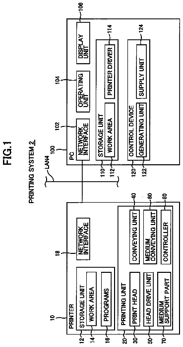
FIG. 1 is an explanatory diagram schematically illustrating the configuration of a printing system according to an embodiment of the invention.
FIG. 2 is an explanatory diagram schematically illustrating the configuration of a PC.
FIG. 3 is an explanatory diagram schematically illustrating the configuration of a printer.
FIG. 4 is a block diagram illustrating the functional configuration of the PC.
FIG. 5 is a block diagram illustrating the functional configuration of the printer.
FIG. 6 is a flowchart illustrating a printing routine of printing in the printing system according to the embodiment of the invention.
FIGS. 7A and 7B are explanatory diagrams illustrating an example of a double-side print produced by printing according to the embodiment of the invention.
FIGS. 8A to 8D are explanatory diagrams illustrating examples of color image data and white image data.
FIG. 9 is a flowchart illustrating the routine of a process executed by a CPU executing a printer driver.
FIG. 10 is a flowchart illustrating the routine of a toning white designation process.
FIGS. 11A and 11B are explanatory diagrams illustrating an example of a UI window of toning white designation.
FIGS. 12A and 12B are explanatory diagrams illustrating a method of measuring the color of a real print.
FIG. 13 is a flowchart illustrating the routine of a color conversion process, an ink color division process, and a halftone process for a toning white image.
FIGS. 14A and 14B are explanatory diagrams partially illustrating examples of toning white image lookup tables.
FIG. 15 is a flowchart illustrating the routine of a color conversion process, an ink color division process, and a halftone process for a color image.
FIG. 16 is an explanatory diagram partially illustrating an example of a lookup table for the color image.
FIG. 17 is a flowchart illustrating the routine of a command generation process.
FIGS. 18A and 18B are explanatory diagrams illustrating an example of a command generated by the command generation process.
FIG. 19 is an explanatory diagram illustrating an example of the details of an ink code table.
FIG. 20 is a flowchart illustrating the routine of a process executed by the printer.
FIG. 21 is an explanatory diagram illustrating the detailed configuration of a raster buffer and a head buffer.
FIGS. 22A to 22C are explanatory diagrams illustrating the configuration of a print head of the printer.
Description of exemplary embodiments
Hereinafter, an embodiment of the invention will be described in the following order.
A. Embodiment
A-1. Configuration of Printing System
A-2. Printing
B. Modified Examples
A. Embodiment
A-1. Configuration of Printing System
FIG. 1 is an explanatory diagram schematically illustrating the configuration of a printing system according to an embodiment of the invention. A printing system 10 according to this embodiment includes a printer 100 and a personal computer (PC) 200. The printer 100 is an ink jet color printer that prints an image by ejecting ink to form ink dots on a print medium (for example, a transparent film). The PC 200 supplies print data to the printer 100 and functions as a print control apparatus that controls printing of the printer 100. The printer 100 and the PC 200 are connected to each other to enable information communication in a wired or a wireless manner. Specifically, the printer 100 and the PC 200 are connected to each other by a USB cable in this embodiment. In FIG. 1, an actual print (hereinafter, also referred to as a "real print RP") produced by a gravure printing apparatus, for example, is shown.
The printer 100 according to this embodiment is a printer that executes printing using a total of seven kinds of ink, that is, cyan (C) ink, magenta (M) ink, yellow (Y) ink, black (K) ink, light cyan (Lc) ink, light magenta (Lm) ink, and white (W) ink. As described below, the printing system 10 according to this embodiment executes printing by forming two color images and two toning white images on a transparent film as a print medium to make a print (hereinafter, also referred to as a "both-side print") on which a color image can be viewed from both sides of the print medium.
In the specification, a "white color" includes not only a white color which is a surface color of an object reflecting all wavelengths of the visible light by 100% precisely, but also a color, such as a "white-looking white color", which is a normally accepted white color. The "white color" is not limited to pure white, as long as
a color of a hue range in which the expression in the Lab system falls within a circle with the radius of 20 on the a*b* plane and L* is equal to or more than 70 when the color measurement apparatus Eye-one Pro made by X-Rite corporation measures a color under the condition that a color measurement mode is a spot color measurement, a light source is D50, backing is black, and a print medium is a transparent film;
a color of a hue range in which the expression in the Lab system falls within a circle with the radius 20 on the a*b* plane and L* is equal to or more than 70 when the color measurement apparatus CM 2022 made by Minolta corporation measures a color under the condition that a color measurement mode is D502.degree. view and an SCF mode and a backing color is white; and
the color of ink used as the backing of an image as disclosed in JP-A-2004-306591 is used as the color of the backing In the specification, adjusting a white color by mixing another color ink with white color ink is called "white color toning". In addition, a white color (adjusted white color) produced by the white color toning is called "toning white color" and an image organized by the toning white color is called a "toning white image".
FIG. 2 is an explanatory diagram schematically illustrating the configuration of the PC 200. The PC 200 includes a CPU 210, a ROM 220, a RAM 230, a USB interface (USB I/F) 240, a network interface (N/W I/F) 250, a display interface (display I/F) 260, a serial interface (serial I/F) 270, a hard disk drive (HDD) 280, and a CD drive 290. The constituent elements of the PC 200 are connected to each other via a bus.
The PC 200 is connected to the printer 100 via the USB interface 240. A USB interface of a color measurement machine CM is connected to the USB interface 240 of the PC 200. A monitor MON serving as a display device is connected to the display interface 260. A keyboard KB and a mouse MOU serving as input devices are connected to the serial interface 270. The configuration of the PC 200 illustrated in FIG. 2 is just an example. Some of the constituent elements of the PC 200 may be omitted or a new constituent element may be added to the PC 200.
FIG. 3 is an explanatory diagram schematically illustrating the configuration of the printer 100. The printer 100 includes a CPU 110, a ROM 120, a RAM 130, a head controller 140, a print head 144, a carriage controller (CR controller) 150, a carriage motor (CR motor) 152, a print medium feeding controller (PF controller) 160, a print medium feeding motor (PF motor) 162, a USB interface (USB I/F) 170, a network interface (N/W I/F) 180, and a rewind mechanism 190. The constituent elements of the printer 100 are connected to each other via a bus.
The CPU 110 of the printer 100 serves as a controller that performs overall control of the operation of the printer 100 by executing a computer program stored in the ROM 120. The print head 144 of the printer 100 is mounted on a carriage (not shown). The carriage controller 150 controls the carriage motor 152 to reciprocate the carriage in predetermined directions. In this way, a main scanning operation is realized in such a manner that the print head 144 reciprocates in a predetermined direction (main scanning direction) of the print medium. The print medium feeding controller 160 controls the print medium feeding motor 162 to execute a sub-scanning operation of transporting the print medium in a direction (sub-scanning direction) perpendicular to the main scanning direction. The print head 144 has a nozzle group (see FIGS. 22A to 22C) ejecting ink. The head controller 140 controls ink ejection from the nozzle group by the print head 144 in interlock with the main scanning operation and the sub-scanning operation. In this way, an image is formed on the print medium (printing of an image). The rewind mechanism 190 is a mechanism that rewinds the print medium to form a new image on the print medium on which an image is formed. Since the configuration of the rewind mechanism 190 is disclosed in JP-A-2008-74063, the detailed description is omitted herein.
FIG. 4 is a block diagram illustrating the functional configuration of the PC 200. The hard disk drive 280 (see FIG. 2) of the PC 200 stores an application program AP as a computer program to be executed by the CPU 210 and a printer driver 300. The application program AP is a program used to set, create, and edit an image (hereinafter, also referred to as a "print image") to be printed on a transparent film as a print medium. The CPU 210 executes the application program AP to set, create, and edit the print image.
When a user gives a print execution instruction, the CPU 210 executing the application program AP outputs color image data Cdata, white image data WIdata, and image order designation information SS to the printer driver 300. More specifically, first color image data Cdata1 and second color image data Cdata2 used to form first and second color images, respectively, and first white image data WIdata1 and second white image data WIdata2 used to form first and second toning white images, respectively, are output from the application program AP to the printer driver 300. The details of the data are described in "A-2. Printing".
The printer driver 300 (see FIG. 4) is a program used to control the printer 100 (see FIG. 1) and print the print image. The CPU 210 (see FIG. 2) executes the printer driver 300 to realize print control of an image printed by the printer 100.
As shown in FIG. 4, the printer driver 300 includes a color image ink division process module 310, a color image halftone process module 320, a toning white designation module 330, a toning white image color conversion module 340, a toning white image ink color division process 350, a toning white image halftone process module 360, and a command generation module 370. The toning white designation module 330 includes a UI control module 332. The hard disk drive 280 (see FIG. 2) of the PC 200 stores a color image lookup table (LUT) LUTc, a color image halftone (HT) resource HTc, a toning white image lookup table (LUT) LUTw, a toning white image halftone (HT) resource HTw, and an ink code table ICT. The printer driver 300 and the modules execute processes on the basis of the information. The functions of the modules and the details of the information are described in "A-2. Printing".
FIG. 5 is a block diagram illustrating the functional configuration of the printer 100. The ROM 120 (see FIG. 3) of the printer 100 stores a command process module 112 as a computer program to be executed by the CPU 110. As described below, the CPU 110 executes the command process module 112 to realize a command process received from the PC 200. The RAM 130 (see FIG. 3) of the printer 100 includes a raster buffer 132. The raster buffer 132 includes two areas of a color image raster buffer 132c and a toning white image raster buffer 132w. The head controller 140 (see FIG. 3) of the printer 100 includes a head buffer 142. The head buffer 142 includes an upstream head buffer 142u and a downstream head buffer 1421. The function and the detailed configuration of the program and the buffer are described in "A-2. Printing".
A-2. Printing
FIG. 6 is a flowchart illustrating a printing routine of the printing system 10 according to this embodiment. The printing according to this embodiment is a process of forming two color images and two toning white images on a transparent film as a print medium and creating a double-side print Pr on which color images can be viewed from the front and rear sides of the print medium.
FIGS. 7A and 7B are explanatory diagrams illustrating an example of the double-side print Pr created by the printing according to this embodiment. As shown in FIG. 7A, the double-side print Pr is a print created by forming a first color image Ic1, a first toning white image Iw1, a second toning white image Iw2, and a second color image Ic2 in this order on one surface of a transparent film TF as a print medium. In the double-side print Pr, as shown in FIGS. 7A and 7B, the second color image Ic2 and the second toning white image Iw2 are viewed from the one surface (hereinafter, also referred to as an "obverse side Fo") of the transparent film TF, and the first color image Ic1 and the first toning white image Iw1 are viewed from the opposite surface (hereinafter, also referred to as a "reverse side Fr") of the transparent film TF. That is, the double-side print Pr can be used as a print viewed from both sides of the obverse side Fo and the reverse side Fr.
In this embodiment, the two toning white images Iw (the first toning white image Iw1 and the second toning white image Iw2) are formed in the same area on the front side of the transparent film TF. Moreover, the area where the two toning white images Iw are formed is an area including an area where the two color images Ic (the first color image Ic1 and the second color image Ic2) are formed. Therefore, only the second color image Ic2 and the second toning white image Iw2 are viewed from the obverse side Fo and only the first color image Ic1 and the first toning white image Iw1 are viewed from the reverse side Fr.
In the following description, the second color image Ic2 and the second toning white image Iw2 viewed from the obverse side Fo are together referred to as "obverse side images". The first color image Ic1 and the first toning white image Iw1 viewed from the reverse side Fr are together referred to as "reverse side images". A person viewing the double-side print Pr views the reverse side images through the transparent film TF (over the transparent film TF) and views the obverse side images directly (without the transparent film TF).
In the printing according to this embodiment, as described below, the reverse side images are first formed, the print medium is rewound, and then the obverse side images are formed. When the reverse side images are formed, the first color image Ic1 is formed and then the first toning white image Iw1 is formed in one area of the print medium. In this embodiment, the printing order in which the color image is formed and then the toning white image is formed is referred to as "color-white printing" or "C-W printing". On the other hand, when the obverse side images are formed, the second toning white image Iw2 is formed and then the second color image Ic2 is formed in one area of the print medium. In this embodiment, the printing order in which the toning white image is formed, and then the color image is formed is referred to as "white-color printing" or "W-C printing".
In step S110 of the printing (see FIG. 6), the CPU 210 (see FIG. 2) executing the application program AP (see FIG. 4) receives a print execution instruction from a user. When receiving the print execution instruction, the CPU 210 outputs the two color image data Cdata and the two white image data WIdata, and the image order designation information SS to the printer driver 300 (see FIG. 4). The color image data Cdata is data for designating a color image in a print image. The white image data WIdata is data for designating a white area Aw (which is described below) in a print image. The image order designation information SS is information for designating an order, in which images are formed on the basis of the image data, for the respective image data. That is, the image order designation information SS is information for designating whether the respective image is data used to form the reverse side images (see FIGS. 7A and 7B) or data used to form the obverse side image. The color image data Cdata, the white image data WIdata, the image order designation information SS are created and set in accordance with the application program AP.
FIGS. 8A to 8D are explanatory diagrams illustrating examples of the color image data Cdata and the white image data WIdata. FIG. 8A conceptually shows the first color image data Cdata1 used to form the first color image Ic1 (see FIGS. 7A and 7B). FIG. 8C conceptually shows the second color image data Cdata2 used to form the second color image Ic2. In this embodiment, the respective color image data Cdata are data for designating the color of pixels of the print image to 8-bit C, M, Y, and K values when only an area used to form the color image IC is emphasized. The respective color data Cdata are data for designating the color of the color image Ic for the pixels corresponding to the color image Ic and are data (for example, C, M, Y, and K=0) for indicating that no color image is formed for the remaining pixels. In the examples of FIGS. 8A to 8D, the color image Ic is a character or a figure. However, the color image Ic may be a photo or an illustration.
FIG. 8B conceptually shows the first white image data WIdata1 used to the first toning white image Iw1 (see FIGS. 7A and 7B). FIG. 8D conceptually shows the second white image data WIdata2 used to form the second toning white image Iw2. In this embodiment, the respective white image data WIdata are data designating the color of each pixel of the print image as an 8-bit W value when the color image IC is excluded. The range of the W value is one from 0 to 255. The respective white image data WIdata becomes data (for example, W=255) indicating that the toning white image Iw is formed for the pixels corresponding to the white area Aw (which is an area where the toning white image Iw is formed) of the print image and becomes data (for example, W=0) indicating that no toning white image Iw is formed for the pixels corresponding to a non-white area An (where is an area where no toning white image Iw is formed). The white image data WIdata may be 2-bit data.
In step S120 of the printing (see FIG. 6), a process by the CPU 210 executing the printer driver 300 (see FIG. 4) is executed. FIG. 9 is a flowchart illustrating a routine of the process by the CPU 210 executing the printer driver 300. In step S210, the CPU 210 receives the color image data Cdata, the white image data WIdata, and the image order designation information SS for the obverse side images and the reverse side images output from the application program AP (see FIG. 4).
In step S220 (see FIG. 9), the toning white designation module 330 (see FIG. 4) executes a toning white designation process. The toning white designation process is a process of designating the color of the white area Aw (see FIGS. 8B and 8D) of the first toning white image Iw1 and the second toning white image Iw2. The color of the white area Aw of the first toning white image Iw1 and the color of the white area Aw of the second toning white image Iw2 are set independently of each other.
FIG. 10 is a flowchart illustrating the routine of the toning white designation process. In step S310, the UI control module 332 (see FIG. 4) of the toning white designation module 330 displays a UI window for the toning white designation on the Monitor MON (see FIG. 2) of the PC 200.
FIGS. 11A and 11B are explanatory diagrams illustrating an example of the UI window for the toning white designation. As shown in FIG. 11A, a UI window W1 for the toning white designation according to this embodiment has a sample image display area Sa, two slider bars Sl1 and Sl2, an ab plane display area P1, a setting image designation field Se1, a value input box Bo1, a measurement button B1, an OK button B2, and an auto button B5.
On the UI window W1 for the toning white designation shown in FIG. 11A, the sample image display area Sa is an area where a designated toning white sample image is displayed. The sample image display area Sa is divided into two areas on the right and left sides. On the right side, an area (white backing area) expresses the toning white on a white backing On the right side, an area (black backing area) exists for toning white on a black backing The outermost circumferential area of the sample image display area Sa is an area indicating the backing color (white or black). The area inside the outermost circumferential area is an area indicating the toning white. In the middle of the sample image display area Sa, a color image (image "A" in the drawing) is expressed on both the white backing area and the black backing area. The color and form of the color image can be arbitrarily set.
On the UI window W1 for the toning white designation, the value input box Bo1 is an area where an L* value (hereinafter, simply referred to as an "L value"), an a* value (hereinafter, simply referred to as an "a value"), a b* value (hereinafter, simply referred to as a "b value"), and a T value are input to designate the toning white. The L value is a value indicating brightness of the toning white and correlates with the amount of black (K) ink when the toning white image is printed. The a value and the b value are values indicating chromaticity along a red-green axis and a yellow-green axis of the toning white and correlate with the amount of color ink when the toning white image is printed. The T value is a value indicating the density and correlates with the amount of ink per unit area when the toning white image is printed. That is, the T value correlates with transmittance of a backing color.
On the UI window W1 for the toning white designation, the slider bars Sl1 and Sl2, and the ab plane display area P1 are areas where an Lab value and a T value are input to designate the toning white.
On the UI window W1 for the toning white designation, the setting image designation field Se1 is a field for designating a toning white designation target image (the first toning white image Iw1 or the second toning white image Iw2). That is, the setting image designation field Se1 is a field for determining whether the toning white designation target image is the first toning white image Iw1 (see FIG. 7A) of the reverse side image or the second toning white image Iw2 of the obverse side image.
When the UI window W1 for the toning white designation is initially displayed, the display state of the value input box Bo1, the sample image display area Sa, and the like is the display state corresponding to a default toning white. For example, the default state is a display state corresponding to the Lab value and the T value set in advance as the color of the white ink of the printer 100.
When the UI window W1 for the toning white designation is displaced, the UI control module 332 (see FIG. 4) monitors whether the user executes an operation using the keyboard KB or the mouse MOU (see FIG. 2) (step S320 in FIG. 10). When it is determined that the operation is executed (step S320: Yes) and the operation is executed using none of the OK button B2, the auto button B5, and the measurement button B1 (step S330: NO, step S332: No, and step S340: No), the UI control module 332 acquires a value corresponding to the operation (step S360), displays the acquired value on the value input box Bo1 (step S370), and then updates the display of the sample image display area Sa (step S380).
For example, when the user operates the keyboard KB (see FIG. 2) to select the value input box Bo1 and simultaneously inputs a value, the input value is displayed on the value input box Bo1 and the color of the sample image display area Sa is changed to a color (toning white) specified by the input value. When the user changes the a value or the b value in the value input box Bo1, the tinge of the color (toning white) of the sample image display area Sa is changed. When the user changes the L value in the value input box Bo1, the brightness of the sample image display area Sa is changed. When the user changes the T value in the value input box Bo1, the transmittance of the backing color is changed. Therefore, the brightness of the color in the black backing area of the sample image display area Sa is changed but the brightness of the color of the white backing area is not changed.
For example, when the user operates the mouse MOU (see FIG. 2) to changes the position of the slider bar Sl1, the L value corresponding to the position is acquired, and thus the color of the sample image display area Sa is changed to a color specified by the acquired value. Similarly, when the user operates the mouse MOU to change the position of the slider bar Sl2, the T value corresponding to the position is acquired, and thus the color of the sample image display area Sa is changed. In addition, when the user operates the mouse MOU to change the position of the designated point (indicated by X in the drawing) of the ab plane display area P1, the a value and the b value corresponding to the position of X are acquired, and thus the color of the sample image display area Sa is changed.
The value input box Bo1, the slider bars Sl1 and Sl2, and the ab plane display area P1 interlock with each other. That is, when the value is changed for the value input box Bo1, the positions of the slider bars Sl1 and Sl2 or the position of X in the ab plane display area P1 are changed. Similarly, when the positions of the slider bars Sl1 and Sl2 or the position of X in the ab plane display area P1 are changed, the changed designation value is displayed on the value input box Bo1.
In this embodiment, the toning white can be designated by measuring the color of the real print RP (see FIG. 1). When the toning white is designated by measuring the color of the real print RP, the printing can be realized so as to precisely reproduce the color of the white portion of the real print RP.
FIGS. 12A and 12B are explanatory diagrams illustrating a method of measuring the color of the real print RP. The real print RP is a print in which an image of a white portion Pw and an image of a color portion Pc are formed on a print medium PM. As shown in FIG. 12A, color measurement is executed by setting an arbitrary point of the white portion Pw of the real print RP as a measurement point MP and measuring the color (the Lab value and the T value) of the measurement point MP by the color measurement apparatus CM (see FIG. 2). Color measurement methods include a method of measuring the white backing color by placing the real print RP on the white backing Bw and a method of measuring the black backing color by placing the real print RP on the black backing Bb. As shown in FIG. 12B, the color measurement value (L value) obtained upon measuring the white backing color may be different from that obtained upon measuring the black backing color due to the density of the white portion Pw of the real print RP. In this embodiment, the measurement of the white backing color is executed to obtain the Lab value and the measurement of the black backing color is executed to obtain the T value.
When it is determined that the operation is executed in step S320 of FIG. 10 (step S320: Yes), the operation is executed using none of the OK button B2 and the auto button B5 (step S330: No and step S332: No), and it is determined that the operation is executed using the measurement button B1 (step S340: Yes), the UI control module 332 (see FIG. 4) displays a UI window W2 for the color measurement shown in FIG. 11B on the monitor MON (see FIG. 2) of the PC 200 (step S350).
The UI window W2 (see FIG. 11B) for the color measurement is a UI window for designating the toning white by measuring the color of the real print RP. The UI window W2 for the color measurement has a backing selection area Se2, a color measurement value box Bo2, a measurement button B3, and an OK button B4. The backing selection area Se2 is an area for selecting one of the measurement of the white backing color and the measurement of the black backing color. The user selects a color measurement method in the backing selection area Se2 and also selects the measurement button B3 to execute color measurement in accordance with the selected method. When the color measurement is completed, the values (the Lab value and the T value) corresponding to the color measurement result are obtained (step S360 in FIG. 10) and are displayed on the color measurement value display box Bo2 (step S370). When the user selects the OK button B4, the UI window W1 (see FIG. 11A) for the toning white designation is again displayed. At this time, the displays of the sample image display area Sa and the value input box Bo1 of the UI window W1 of the toning white designation are changed on the basis of the color measurement result (step S380).
When it is determined that the operation is executed in step S320 of FIG. 10 (step S320: Yes), and that the operation is executed using not the OK button B2 (step S330: No) but the auto button B5 (step S332: Yes), the automatic setting of the toning white is executed (step S334). In this embodiment, the automatic setting of the toning white is executed in accordance with the color image. Specifically, when the toning white designation target image is the first toning white image Iw1 organizing the reverse side image, the color of the toning white is set to a white having the tinge of the complementary color of the color of the first color image Ic1 organizing the same reverse side image. For example, when the color of the first color image Ic1 is red, the color of the first toning white image Iw1 is set to a white (white with cyan) having a tinge of cyan which is the complementary color of red. When the same toning white designation target image is the second toning white image Iw2 organizing the obverse side image, the color of the toning white is set to a white having a tinge of the complementary color of the color of the second color image Ic2 organizing the same obverse side image. In this way, since the toning white is set automatically, the color of the color image Ic is emphasized and thus the double-side print Pr with an improved contrast ratio can be generated.
When the first color image Ic1 or the second color image Ic2 is not a single-color image, the color of the toning white is set to a white having a tinge of the complementary color of the representative color of the first color image Ic1 or the second color image Ic2. The representative color of the first color image Ic1 or the second color image Ic2 is determined on the basis of the average of the pixel values of the color image Ic, for example.
The automatic setting of the toning white corresponding to the color image may be executed in accordance with another method. For example, scene determination of the color image Ic is executed and a predetermined toning white is set depending on the determined scene. A toning white having a tinge of the color (representative color) of the color image Ic to a preset degree may be set. The representative color of the color image Ic may be determined by determining a main subject by a process of dividing the area of the color image Ic, detecting a face, and acquiring focus position information.
The description continues in the full USPTO document.
 Lapsed, fee not paid10 drawings