Lapsed, fee not paid5 drawings
Cameras, Displays & Optics · US 8,548,319 B1
Camera lens shade assembly
A camera lens shade assembly includes an elongated member having a first end and a second end.
US 8,548,347 B2 · Assignee: Sharp Kabushiki Kaisha · Inventors: Tomita; Norio
Sheet 1 of 7 from the published document. All sheets in the USPTO PDF
A color image forming apparatus including a test pattern formation portion that forms test patterns of a plurality of colors in an image formation area in which images of the plurality of colors are formed on an image carrier and in an image non-formation area outside the image formation area on the image carrier, a detection portion that detects a shift of each of the test patterns of the plurality of colors formed in the image formation area and a shift of each of the test patterns of the plurality of colors formed in the image non-formation area, a computing portion that obtains, for each color, an offset value indicating an offset between the shift of the test pattern in the image non-formation area and the shift of the test pattern in the image formation area, and a storage portion that stores the offset value for each color.
This application claims priority under 35 U.S.C. .sctn.119(a) on Patent Application No. 2010-154872 filed in Japan on Jul. 7, 2010, the entire contents of which are herein incorporated by reference. The present invention relates to an electrophotographic color image forming apparatus such as a color printer, a color copying machine, or a color facsimile machine. In color image forming apparatuses of this type, there is the problem of color shifts since a color image is formed by superimposing images of a plurality of colors. For example, a color image forming apparatus has a configuration in which latent images are respectively written on a plurality of latent image carriers (photosensitive drums) corresponding to a plurality of colors, the latent images on the latent image carriers are developed, and images of the colors are respectively formed on the latent image carriers, transferred
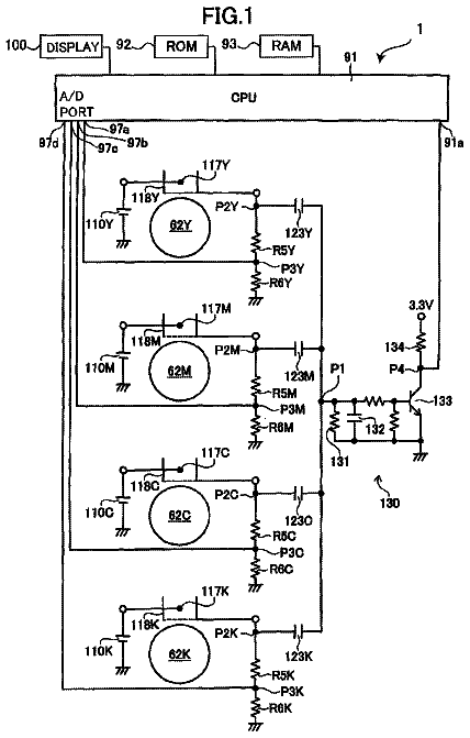
1 of 7 drawing sheets so far from the published document, cropped to the drawing. Every sheet is in the USPTO PDF.
What the patent claimed, word for word. All of it is now free to use.
This application claims priority under 35 U.S.C. .sctn.119(a) on Patent Application No. 2010-154872 filed in Japan on Jul. 7, 2010, the entire contents of which are herein incorporated by reference.
The present invention relates to an electrophotographic color image forming apparatus such as a color printer, a color copying machine, or a color facsimile machine.
In color image forming apparatuses of this type, there is the problem of color shifts since a color image is formed by superimposing images of a plurality of colors. For example, a color image forming apparatus has a configuration in which latent images are respectively written on a plurality of latent image carriers (photosensitive drums) corresponding to a plurality of colors, the latent images on the latent image carriers are developed, and images of the colors are respectively formed on the latent image carriers, transferred from the latent image carriers to an image carrier (transfer belt), superimposed and formed on the image carrier, and further transferred from the image carrier to a recording medium, whereby a color image is formed on the recording medium. In such a color image forming apparatus, images of a plurality of colors may be shifted when the images are transferred from the latent image carriers to the image carrier, and thus a color shift may occur, which deteriorates the quality of a color image.
For this reason, in the invention described in JP 2009-150997A, color shift detection patterns of a plurality of colors are formed in an image formation area of an image carrier (transport belt), shifts of the color shift detection patterns of the colors are detected, and the positions of images of the colors to be formed in the image formation area of the image carrier are corrected based on the shifts of the color shift detection patterns of the colors, thereby preventing color shifts.
However, in the case where such color shift detection patterns of a plurality of colors are formed in the image formation area of the image carrier and detected as in the invention described in JP 2009-150997A, when a normal image is formed in the image formation area, the color shift detection patterns of the colors cannot be formed in the image formation area. Accordingly, it has been necessary to form and detect the color shift detection patterns at the interval of image formation operations or in a state in which an image formation operation is stopped, and thus it has been necessary to set a special period for this.
In the invention described in JP 2005-99716A, an image formation area in the center in the width direction of an image carrier (transfer belt) and image non-formation areas at both edges in the width direction thereof are distinguished, and thus it is possible to detect pitch detection patterns in the image non-formation areas even when an image is formed in the image formation area of the image carrier.
However, the degree of, for instance, color shifts due to so-called bow (curved scanning lines from a light scanning apparatus to a photosensitive body) and the like differs in the center of the image carrier and at both edges thereof. Accordingly, as in the invention described in JP 2005-99716A, even if detection patterns are provided in the image non-formation areas at both edges in the width direction of the image carrier and detected, and then the detection result is used for correction of an image in the center of the image carrier, the correction error was large.
On the other hand, in the invention described in JP 2007-65500A, although bow, for instance, is reduced by pressing a long lens through which scanning beams for latent image writing pass, it is difficult to effectively eliminate color shifts due to bow and the like with such a method. Accordingly, even if the invention described in JP 2005-99716A is combined with the invention described in JP 2007-65500A, color shifts in the center of the image carrier could not be accurately corrected.
As described, in the invention described in JP 2009-150997A, color shift detection patterns of a plurality of colors are formed in the image formation area of the image carrier and detected, and thus it has been necessary to form and detect the color shift detection patterns at the interval of image formation operations or in a state in which an image formation operation is stopped, and thus it has been necessary to set a special period for this.
In the invention described in JP 2005-99716A, since detection patterns in the image non-formation areas of the image carrier are detected, even when an image is formed in the image formation area of the image carrier, the detection patterns can be detected. However, even if the detection result is used for correction of an image in the center of the image carrier, a correction error was large due to the influence of bow and the like.
Furthermore, in the invention described in JP 2007-65500A, although bow, for instance, is reduced by pressing the long lens through which scanning beams pass, it is difficult to effectively eliminate color shifts due to bow and the like. Accordingly, even if the invention described in JP 2005-99716A and the invention described in JP 2007-65500A are combined, color shifts in the center of the image carrier could not be accurately corrected.
The present invention has been conceived in light of the above conventional problems, and an object thereof is to provide a color image forming apparatus that can detect and correct color shifts even during an image formation operation, and furthermore effectively reduce the influence of bow and the like.
In order to solve the above problems, a color image forming apparatus of the present invention is a color image forming apparatus that forms test patterns of a plurality of colors on an image carrier, detects a shift of each of the test patterns of the plurality of colors formed on the image carrier, and corrects a position of an image of each of the plurality of colors to be formed on the image carrier based on the shifts of the test patterns of the plurality of colors, the apparatus including a test pattern formation portion that forms the test patterns of the plurality of colors in an image formation area in which images of the plurality of colors are formed on the image carrier and in an image non-formation area outside the image formation area on the image carrier, a detection portion that detects a shift of each of the test patterns of the plurality of colors formed in the image formation area and a shift of each of the test patterns of the plurality of colors formed in the image non-formation area, a computing portion that obtains, for each color, an offset value indicating an offset between the shift of the test pattern in the image non-formation area and the shift of the test pattern in the image formation area, and a storage portion that stores the offset value for each color.
In the color image forming apparatus of the present invention as described, the test patterns of the colors are formed in both the image formation area and the image non-formation area of the image carrier, shifts of the test patterns of the colors formed in the image formation area and shifts of the test patterns of the colors formed in the image non-formation area are detected, and for each color, an offset value indicating an offset between a shift of a test pattern in the image non-formation area and a shift of a test pattern in the image formation area is obtained and stored in the storage portion. The shifts of the test patterns of the colors in the image formation area can be derived based on such offset values for the colors and shifts of the test patterns of the colors formed in the image non-formation area. Specifically, without forming the test patterns of the colors in the image formation area and directly detecting the shifts thereof, as long as the offset values for the colors are obtained in advance and stored, the shifts of the test patterns of the colors in the image formation area can be derived by detecting the shifts of the test patterns of the colors formed in the image non-formation area.
In the color image forming apparatus of the present invention, the offset values are obtained in advance and stored in the storage portion, the test pattern formation portion forms the test patterns of the plurality of colors in the image non-formation area, and the detection portion detects a shift of each of the test patterns of the plurality of colors formed in the image non-formation area, the computing portion has a function of obtaining, for each color, a shift of a test pattern in the image formation area based on the shift of the test pattern formed in the image non-formation area and the offset value stored in the storage portion, and positions of images of the plurality of colors to be formed on the image carrier are corrected based on the shifts of the test patterns of the plurality of colors in the image formation area obtained by the computing portion.
If the test patterns of the colors are formed in the image non-formation area, and the shifts of the test patterns of the colors are detected as described, the shifts of the test patterns of the colors in the image formation area can be obtained based on the offset values for the colors and the shifts of the test patterns of the colors, and the positions of images of the colors in the image formation area can be corrected. Specifically, without forming the test patterns of the colors in the image formation area, by obtaining the shifts thereof, the positions of images of the colors in the image formation area can be corrected.
Furthermore, in the color image forming apparatus of the present invention, formation of the test patterns in the image non-formation area by the test pattern formation portion and detection of the shifts of the test patterns in the image non-formation area by the detection portion are performed when images of the plurality of colors are formed in the image formation area.
Since it is not necessary to form the test patterns of the colors in the image formation area, even when images of the colors are formed in the image formation area, it is possible to correct the positions of images of the colors in the image formation area by forming the test patterns in the image non-formation area and detecting the shifts thereof.
In the color image forming apparatus of the present invention, formation of the test patterns in the image formation area and the test patterns in the image non-formation area by the test pattern formation portion and detection of the shifts of the test patterns in the image formation area and the shifts of the test patterns in the image non-formation area by the detection portion are performed when images of the plurality of colors are not formed in the image formation area.
In order to obtain offset values for the colors, it is necessary to form the test patterns of the colors in the image formation area and in the image non-formation area of the image carrier, and detect the shifts of the test patterns of the colors. Accordingly, offset values for the colors are derived when images of the colors are not formed in the image formation area. As described, the offset values for the colors are obtained and stored in the storage portion, and thereafter shifts of test patterns of the colors in the image formation area are obtained, based on the offset values for the colors and the shifts of the test patterns of the colors in the image non-formation area.
In the color image forming apparatus of the present invention, the image non-formation area is provided on both sides of the image carrier, and the image formation area is provided between the image non-formation areas on the image carrier, the test pattern formation portion forms the test patterns of the plurality of colors in both edge portions of the image formation area and in the image non-formation areas, the detection portion, for each color, divides the test patterns in both edge portions of the image formation area and the test patterns in the image non-formation areas into two groups each made up of adjacent patterns, and obtains, for each group, an offset value indicating an offset between a shift of the test pattern in the image non-formation area and a shift of the test pattern in the image formation area, and the storage portion stores two offset values for each color.
By obtaining and using two offset values as described, it is possible to more accurately correct the positions of images of the colors to be formed on the image carrier.
Furthermore, in the color image forming apparatus of the present invention, a position of a test pattern of one of the plurality of colors is used as a reference position, and a shift of each of the test patterns of the plurality of colors is obtained as a shift of a position of a test pattern of another color relative to the reference position.
The color image forming apparatus of the present invention includes a latent image carrier for each of the plurality of colors, a latent-image writing portion that writes a latent image on each of the latent image carriers, a development portion that develops the latent image on each of the latent image carriers, and forms images of the plurality of colors on the latent image carriers, and a transfer portion that transfers the images of the plurality of colors from the latent image carriers to the image carrier, and forms the images of the plurality of colors on the image carrier, wherein the latent-image writing portion adjusts a writing timing at which a latent image is written on each of the latent image carriers according to the shifts of the test patterns of the plurality of colors obtained by the computing portion, and corrects positions of images of the plurality of colors to be formed on the image carrier.
Here, latent images are respectively written on the plurality of latent image carriers (photosensitive drums) corresponding to the colors, and the latent images on the latent image carriers are developed. Then, images of the colors are respectively formed on the latent image carriers, transferred from the latent image carriers to the image carrier (transfer belt), superimposed and formed on the image carrier, and further transferred from the image carrier to a recording medium, whereby a color image is formed on the recording medium. In this case, the positions of images of the colors to be formed on the image carrier can be corrected by adjusting writing timings at which latent images are respectively written on the latent image carriers.
Note that the present invention is also applicable to color image forming apparatuses having other configurations. For example, the present invention is also applicable to a color image forming apparatus that directly transfers images of the colors from latent image carriers to a recording medium (recording paper).
According to the present invention as described, the test patterns of the colors are formed in all the image formation area and the image non-formation areas of the image carrier, shifts of the test patterns of the colors formed in the image formation area and shifts of the test patterns of the colors formed in the image non-formation areas are detected, and for each color, an offset value indicating an offset between a shift of a test pattern in the image non-formation area and a shift of a test pattern in the image formation area is obtained and stored in the storage portion. The shifts of the test patterns of the colors in the image formation area can be derived based on such offset values for the colors and shifts of the test patterns of the colors formed in the image non-formation areas. Specifically, without forming the test patterns of the colors in the image formation area and directly detecting the shifts thereof, as long as the offset values for the colors are obtained in advance and stored, the shifts of the test patterns of the colors in the image formation area can be derived by detecting the shifts of the test patterns of the colors formed in the image non-formation areas.
FIG. 1 is a cross-sectional view showing one embodiment of a color image forming apparatus of the present invention.
FIG. 2 is a block diagram showing a control system of the color image forming apparatus in FIG. 1.
FIG. 3A is a plan view showing an intermediate transfer belt and registration sensors in the color image forming apparatus in FIG. 1.
FIG. 3B is a lateral view showing the intermediate transfer belt and the registration sensors in the color image forming apparatus in FIG. 1.
An upper diagram of FIG. 4 shows shifts .DELTA.y1 and .DELTA.y2 in the sub-scanning direction of a main scanning line at both edge portions of an image formation area of the intermediate transfer belt, shifts .DELTA.y3 and .DELTA.y4 in the sub-scanning direction of the main scanning line in image non-formation areas, a first sub-scanning offset value (.DELTA.y3-.DELTA.y1), and a second sub-scanning offset value (.DELTA.y4-.DELTA.y1), a middle diagram of FIG. 4 shows a main scanning line whose position has been adjusted by an average shift (.DELTA.y1+.DELTA.y2)/2 in the sub-scanning direction, and a lower diagram of FIG. 4 shows a main scanning line whose position has been adjusted by the shifts .DELTA.y3 and .DELTA.y4 in the sub-scanning direction in the image non-formation areas.
An upper diagram of FIG. 5 shows shifts .DELTA.x1 and .DELTA.x2 in the main scanning direction of the main scanning line at both edge portions of the image formation area of the intermediate transfer belt, shifts .DELTA.x3 and .DELTA.x4 in the main scanning direction of the main scanning line in the image non-formation areas, a first main scanning offset value (.DELTA.x3-.DELTA.x1), and a second main scanning offset value (.DELTA.x4-.DELTA.x2), a middle diagram of FIG. 5 shows pixels Px on a main scanning line L whose position has been adjusted by the shifts .DELTA.x1 and .DELTA.x2 in the main scanning direction at both edge portions of the image formation area, and a lower diagram of FIG. 5 shows pixels Px on a main scanning line L whose position has been adjusted by the shifts .DELTA.x3 and .DELTA.x4 in the main scanning direction in the image non-formation areas.
FIG. 6 is a flowchart showing a procedure for obtaining the first and second sub-scanning offset values and the first and second main scanning offset values.
FIG. 7 is a flowchart showing a procedure for obtaining an average shift in the sub-scanning direction in the image formation area of the intermediate transfer belt and shifts in the main scanning direction at both edge portions of the image formation area.
The following is a detailed description of an embodiment of the present invention with reference to accompanying drawings.
FIG. 1 is a cross-sectional view showing one embodiment of a color image forming apparatus of the present invention. This color image forming apparatus 1 is a so-called multi-function peripheral that has a scanner function, a copying function, a printer function, a facsimile function, and the like, and transmits an image of an original read by an image reading apparatus 41 to the outside (which corresponds to the scanner function), and records and forms the image of the read original or an image received from the outside onto recording paper in color or monochrome (which corresponds to the copying function, the printer function, and the facsimile function).
In order to print an image on recording paper, the color image forming apparatus 1 is provided with a laser exposing apparatus 11, development apparatuses 12, photosensitive drums 13, drum cleaning apparatuses 14, charging units 15, an intermediate transfer belt apparatus 16, a fixing apparatus 17, a paper transport path S, a paper feed tray 18, a paper discharge tray 19, and the like.
Image data handled in the color image forming apparatus 1 corresponds to a color image using black (K), cyan (C), magenta (M), and yellow (Y), or corresponds to a monochrome image using a single color (for example, black). Accordingly, four each of the development apparatuses 12, the photosensitive drums 13, the drum cleaning apparatuses 14, and the charging units 15 are provided such that four types of toner images corresponding to the colors are formed, with these being respectively associated with black, cyan, magenta, and yellow, thereby constituting four image stations Pa, Pb, Pc, and Pd.
The photosensitive drums 13 each have a photosensitive layer on the surface thereof. The charging units 15 serve as charging means for respectively charging the surface of the photosensitive drums 3 uniformly to a predetermined potential, and contact roller-type or contact brush-type charging units, or otherwise charger-type charging units are used.
The laser exposing apparatus 11 is a laser scanning unit (LSU) provided with laser diodes and reflection mirrors, and exposes the charged surface of the photosensitive drums 3 according to image data to form electrostatic latent images according to the image data on the surface thereof.
The development apparatuses 12 develop the electrostatic latent images respectively formed on the surface of the photosensitive drums 13 with toner of the colors, and form a toner image on the surface of the photosensitive drums 13. The drum cleaning apparatuses 14 respectively remove and collect toner remaining on the surface of the photosensitive drums 13 after development and image transfer.
The intermediate transfer belt apparatus 16 is disposed above the photosensitive drums 13, and is provided with an intermediate transfer belt 21, an intermediate transfer belt drive roller 22, an idler roller 23, four intermediate transfer rollers 24, and a belt cleaning apparatus 25.
The intermediate transfer belt 21 is formed as an endless belt using a film. The intermediate transfer belt drive roller 22, the idler roller 23, the intermediate transfer rollers 24, and the like support the intermediate transfer belt 21 in a tensioned manner, and revolve the intermediate transfer belt 21 in the direction of arrow C.
The intermediate transfer rollers 24 are rotatably supported in the vicinity of the intermediate transfer belt 21, and respectively pressed against the photosensitive drums 13 via the intermediate transfer belt 21. The toner images on the surface of the photosensitive drums 13 are sequentially transferred and superimposed on the intermediate transfer belt 21, whereby a color toner image (toner images of the colors) is formed on the intermediate transfer belt 21. The toner images are transferred from the photosensitive drums 13 to the intermediate transfer belt 21, using the intermediate transfer rollers 24 pressed against the back surface of the intermediate transfer belt 21. The intermediate transfer rollers 24 are rollers each having a metal (for example, stainless steel) shaft as a base, with the surface of that shaft being covered with a conductive elastic material (for example, such as EPDM or urethane foam). A high voltage transfer bias (a high voltage of opposite polarity (+) to the toner charging polarity (-)) is applied to the intermediate transfer rollers 24 in order to transfer toner images, and a high voltage is uniformly applied to recording paper with the conductive elastic material.
The toner images on the surface of the photosensitive drums 13 are transferred and layered on the intermediate transfer belt 21 in this way, and become a color toner image indicated by the image data. This color toner image is transported together with the intermediate transfer belt 21, and transferred onto recording paper in a nip region between the intermediate transfer belt 21 and a transfer roller 26a of a secondary transfer apparatus 26.
A voltage (a high voltage of opposite polarity (+) to the toner charging polarity (-)) for transferring the toner images of the colors on the intermediate transfer belt 21 to the recording paper is applied to the transfer roller 26a of the secondary transfer apparatus 26.
The toner images on the intermediate transfer belt 21 may not be completely transferred onto the recording paper by the secondary transfer apparatus 26, thus causing toner to remain on the surface of the intermediate transfer belt 21. This remaining toner causes toner color mixing to occur in a subsequent process. Accordingly, the belt cleaning apparatus 25 removes and collects the remaining toner on the surface of the intermediate transfer belt 21. The belt cleaning apparatus 25 is provided with, for example, a cleaning blade that removes remaining toner by being in contact with the surface of the intermediate transfer belt 21 as a cleaning member. The back side of the intermediate transfer belt 21 is supported by the idler roller 23 at a site where the cleaning blade is in contact.
The recording paper is transported to the fixing apparatus 17 after the color toner image has been transferred thereto in the nip region between the intermediate transfer belt 21 and the transfer roller 26a of the secondary transfer apparatus 26. The fixing apparatus 17 is provided with a heat roller 31, a pressure roller 32, and the like, and sandwiches and transports the recording paper between the heat roller 31 and the pressure roller 32.
The heat roller 31 is controlled so as to have a prescribed fixing temperature based on the detection output of a temperature detector (not shown), and fuses, mixes, and applies pressure to the color toner image transferred onto the recording paper by applying heat and pressure to the recording paper together with the pressure roller 32, thus thermally fixing that color toner image on the recording paper.
The paper feed tray 18 for supplying recording paper is provided in the lower part of the color image forming apparatus 1. The color image forming apparatus 1 is provided with the paper transport path S for feeding recording paper supplied from the paper feed tray 18 to the paper discharge tray 19 via the secondary transfer apparatus 26 and the fixing apparatus 17.
A paper pickup roller 33 is provided at an edge portion of the paper feed tray 18, and recording paper is drawn out sheet-by-sheet from the paper feed tray 18 and transported to the paper transport path S by the paper pickup roller 33.
Paper registration rollers 34, the fixing apparatus 17, transport rollers 35, paper discharge rollers 36, and the like are disposed along the paper transport path S. The transport rollers 35 are small rollers for promoting and assisting the transport of recording paper, and a plurality of sets thereof are provided.
The paper registration rollers 34 temporarily stop the transported recording paper and align the leading edge of the recording paper, and then transport the recording paper in a timely manner in coordination with the rotation of the photosensitive drums 13 and the intermediate transfer belt 21 such that the color toner image on the intermediate transfer belt 21 is transferred onto the recording paper in the nip region between the intermediate transfer belt 21 and the transfer roller 26a of the secondary transfer apparatus 26.
Furthermore, the color toner image is fixed onto the recording paper by the fixing apparatus 17, and the recording paper passes through the fixing apparatus 17, and thereafter the recording paper is discharged facedown on the paper discharge tray 19 by the paper discharge rollers 36.
Further, if printing is performed not only on the front surface of recording paper, but also on the back surface, while the recording paper is being transported by the paper discharge rollers 36, the paper discharge rollers 36 are stopped and then rotated in reverse, the front and back of the recording paper are reversed by causing the recording paper to pass through a reverse path Sr, and then the recording paper is guided to the paper registration rollers 34. As in the case of the front surface of the recording paper, an image is recorded and fixed onto the back surface of the recording paper, and the recording paper is discharged onto the paper discharge tray 19.
The following is a description of the image reading apparatus 41 and an original transport apparatus 42 that are mounted in the upper part of the main body of the color image forming apparatus 1. One far side of the original transport apparatus 42 is pivotably supported by a hinge (not shown) on one far side of the image reading apparatus 41, and the original transport apparatus 42 is opened and closed by the near portion thereof being raised or lowered. When the original transport apparatus 42 is opened, a platen glass 44 of the image reading apparatus 41 is released, and an original is placed on this platen glass 44.
The image reading apparatus 41 is provided with the platen glass 44, a first scanning unit 45, a second scanning unit 46, an imaging lens 47, a CCD (Charge Coupled Device) 48, and the like. The first scanning unit 45 is provided with an illuminating apparatus 51 and a first reflection mirror 52. While moving in the sub-scanning direction at a fixed speed V by the distance according to the original size, the first scanning unit 45 exposes the original on the platen glass 44 with the illuminating apparatus 51, and reflects the reflected light using the first reflection mirror 52 so as to guide the light to the second scanning unit 46, thereby scanning an image on the original surface in the sub-scanning direction. The second scanning unit 46 is provided with second and third reflection mirrors 53 and 54, reflects the reflected light from the original using the second and third reflection mirrors 53 and 54 so as to guide the light to the imaging lens 47 while moving at a speed V/2, following the first scanning unit 45. The imaging lens 47 collects the reflected light from the original onto the CCD 48, and forms the image on the original surface on the CCD 48. The CCD 48 repeatedly scans the image of the original in the main scanning direction, and outputs analog image signals for one main scanning line at each scan.
The image reading apparatus 41 can read not only a stationary original, but also an image on the surface of an original that is being transported by the original transport apparatus 42. In this case, the first scanning unit 45 is moved to a reading range under an original reading glass 55, the second scanning unit 46 is positioned according to the position of the first scanning unit 45, and the transport of an original by the original transport apparatus 42 is started in this state.
In the original transport apparatus 42, a pickup roller 56 is pressed against originals on an original tray 57 and rotated to draw out an original, and then the original is transported through an original transport path 58, caused to pass between the original reading glass 55 and a reading guide plate 59, and further transported from paper discharge rollers 61 to a discharge tray 62. A registration roller 63 that transports an original after aligning the leading edge thereof, and a transport roller 64 that transports the original are disposed along the original transport path 58.
In the original transport, the original surface is illuminated via the original reading glass 55 by the illuminating apparatus 51 of the first scanning unit 45, the reflected light from the original surface is guided to the imaging lens 47 by the reflection mirrors of the first and second scanning units 45 and 46, the reflected light from the original surface is collected on the CCD 48 by the imaging lens 47, and an image on the original surface is formed on the CCD 48, whereby the image on the original surface is read.
In the case where the back surface of an original is read, an intermediate tray 67 is rotated about a shaft thereof as shown by the dotted line, the paper discharge rollers 61 are stopped while an original is being discharged from the paper discharge rollers 61 to the discharge tray 62, and the original is received on the intermediate tray 67. Then, the paper discharge rollers 61 are rotated in reverse so as to guide the original to the registration roller 63 via a reverse transport path 68, whereby the front and back of the original are reversed, and as in the case of an image on the front surface of the original, an image on the back surface of the original is read, the intermediate tray 67 is returned to the original position shown by the solid line, and then the original is discharged from the paper discharge rollers 61 to the discharge tray 62.
The image of the original read by the CCD 48 in this way is outputted as analog image signals from the CCD 48, and the analog image signals are A/D converted into digital image signals (image data). Then, this image data undergoes various image processing, and thereafter is sent to and received by the laser exposing apparatus 11 of the color image forming apparatus 1. In the color image forming apparatus 1, the image is recorded on recording paper, and this recording paper is outputted as a copied original.
FIG. 2 is a block diagram showing a control system of the color image forming apparatus 1 according to the present embodiment. In FIG. 2, a control portion (computing portion) 71 performs overall control of the color image forming apparatus 1, and is constituted by a CPU, a RAM, a ROM, various interfaces, and so on. A print portion 72 corresponds to, for instance, the laser exposing apparatus 11, the development apparatuses 12, the photosensitive drums 13, the drum cleaning apparatuses 14, the charging units 15, the intermediate transfer belt apparatus 16, the fixing apparatus 17, the paper transport path S, the paper feed tray 18, and the paper discharge tray 19 in FIG. 1, and prints a print image on recording paper using an electrophotographic system.
An input operation portion 73 is constituted by a plurality of input keys and a liquid crystal display apparatus, for example. A memory (storage portion) 74 is, for example, a hard disk apparatus (HDD), and stores various data and programs. Four registration sensors (detection portions) 81 to 84 detect test patterns formed on the intermediate transfer belt 21 of the intermediate transfer belt apparatus 16.
For example, the control portion 71 causes the original transport apparatus 42 to transport an original and the image reading apparatus 41 to read an image of the original by controlling the image reading apparatus 41 and the original transport apparatus 42, causes the memory 74 to store image data indicating the image of the original, and causes the print portion 72 to record the image of the original indicated by the image data in the memory 74 on recording paper by controlling the print portion 72.
However, since images of the colors are respectively formed on the photosensitive drums 13 of the image forming stations Pa, Pb, Pc, and Pd, and thereafter the images on the photosensitive drums 13 are sequentially transferred, superimposed, and formed on the intermediate transfer belt 21, transfer positions (image positions) of the images of the colors on the intermediate transfer belt 21 may be shifted, thereby causing color shifts to occur, and thus the quality of a color image may deteriorate.
In view of this, test patterns of the colors are respectively formed on the photosensitive drums 13 of the image forming stations Pa, Pb, Pc, and Pd, the test patterns of the colors on the photosensitive drums 13 are transferred onto the intermediate transfer belt 21, recording positions of the test patterns of the colors on the intermediate transfer belt 21 are detected, and shifts thereof are detected from the recording positions of the test patterns of the colors. The positions of images of the colors to be formed on the photosensitive drums 13 are corrected based on the shifts of the test patterns of the colors, and the images on the photosensitive drums 13 are accurately transferred, superimposed, and formed on the intermediate transfer belt 21, thereby preventing color shifts. The image positions on the photosensitive drums 13 are corrected normally by, for instance, controlling writing timings at which electrostatic latent images are written on the photosensitive drums 13 using scanning beams emitted from the laser diodes of the laser exposing apparatus 11. The image positions in the sub-scanning direction are corrected by adjusting sub-scanning direction positions of main scanning lines on the photosensitive drums 13, and the image positions in the main scanning direction are corrected by adjusting the length and main scanning direction positions of the main scanning lines on the photosensitive drums 13.
Specifically, since there is an image non-formation area on both sides of an image formation area of the intermediate transfer belt 21, test patterns of the colors are formed in both edge portions of the image formation area and in the image non-formation areas, and for each color, the test patterns in both edge portions of the image formation area and the test patterns in the image non-formation areas are divided into two groups each made up of adjacent test patterns. Then, an offset value indicating an offset between a shift of the test pattern in the image non-formation area and a shift of the test pattern in the image formation area is obtained for each group, and these offset values are stored in the memory 74. In this way, two offset values are stored in the memory 74 for each color, and thereafter test patterns of the colors are formed only in the image non-formation areas of the intermediate transfer belt 21, and shifts of the test patterns of the colors are detected. Then, for each color, a shift of the test pattern in the image formation area is obtained based on the two offset values and the detected shifts of the test patterns, and the position of an image to be formed in the image formation area is corrected.
Accordingly, it is not necessary to form test patterns of the colors in the image formation area of the intermediate transfer belt 21 after two offset values have been stored in the memory 74 for each color, and even while images of the colors are being formed in the image formation area of the intermediate transfer belt 21, the positions of images of the colors to be formed in the image formation area can be corrected by merely forming test patterns of the colors in the image non-formation areas. Further, since test patterns in both edge portions of the image formation area and the test patterns in the image non-formation areas are divided into two groups each made up of adjacent test patterns, and offset values respectively obtained from the groups are used, the influence of bow, for instance, can be suppressed, and the positions of images of the colors to be formed in the image formation area can be corrected more accurately.
The following is a detailed description of a procedure for obtaining two offset values for each color in the color image forming apparatus 1 according to the present embodiment.
First, as shown in FIG. 3A, an image formation area 21a in the center and image non-formation areas 21b and 21c on both sides are set on the surface of the intermediate transfer belt 21. Further, the surface of the photosensitive drums 13 also has an image formation area (not shown) that is in contact with the image formation area 21a of the intermediate transfer belt 21 and image non-formation areas (not shown) that are respectively in contact with the image non-formation areas 21b and 21c of the intermediate transfer belt 21.
The description continues in the full USPTO document.
About 6,694 words. The USPTO PDF has it with every drawing.
Fees are due 3.5, 7.5 and 11.5 years after grant. This patent expired on October 1, 2025, so the fee marked "not paid" was the one that went unpaid.
COLOR IMAGE FORMING APPARATUS
Filed Jul 2011 · published Jan 2012Color image forming apparatus
Filed Jul 2011 · granted Oct 2013Earlier publications, parents and continuations. None of them can still be enforced, or this patent would not be listed.
Prior art cited by the examiner or applicant. Useful when you check your own idea for novelty.
Everything on this page comes from the documents linked above.