The present invention relates generally to obtaining the proper position of a prosthetic implant, and more specifically to devices and methods used for achieving the proper axial position and retroversion of a stemmed humeral component during shoulder arthroplasty, as well as to properly positioning a humeral stem provisional, which is inserted on a trial basis during the operation, prior to inserting the permanent stemmed humeral component.
Background of the invention
Shoulder fractures are not uncommon, especially among senior citizens with osteoporosis. In certain instances, shoulder replacement surgery is necessary. One type of fracture that commonly requires shoulder replacement surgery is called a four-part fracture. Such a fracture is characterized by the shoulder being broken into four parts--the lesser tuberosity, the greater tuberosity, the humeral head, and the humeral shaft.
During a shoulder replacement operation (also known as shoulder arthroplasty surgery), a canal found within the humeral shaft is used for receiving the humeral component of the shoulder prosthesis. If necessary, in order to better accommodate the humeral component, the canal may be enlarged using known methods. The humeral component of the prosthesis typically includes a stem and a head, which is a partial sphere that replaces the fractured humeral head. The stem and the head may be two separate components, or they may be a single component. Regardless of whether the humeral component is a single part or two parts, a collar is formed between the stem and the head. Between this collar and the fracture line on the proximal end of the humerus, the fractured lesser and greater tuberosities are normally anchored around the stem of the humeral component, as closely as possible to their original positions.
Before implanting the permanent stemmed humeral component, a temporary component, often called a humeral stem provisional, is temporarily inserted into the humerus to determine the proper placement of the stemmed humeral component. Proper positioning of the final stemmed humeral component is very important. Improper positioning can result in a range of problems from mild discomfort to severe pain, as well as a lack of proper range of motion, depending upon the degree and type of improper positioning. Accordingly, it is important that the humeral stem provisional be properly positioned, and that such proper position can be reliably replicated when implanting the final stemmed humeral component. The two key areas of proper positioning are the stemmed component's axial position and its retroversion.
Currently, several devices are available to assist in properly positioning the stemmed humeral component within the humerus. For example, Tornier.RTM. markets a system under the Aequalis.RTM. name that includes a jig that uses a portion of the anatomy for referencing the position of the humeral implant. However, this jig is relatively large and bulky, and it is difficult to perform a range of motion analysis with the jig in place. Other smaller systems, such as the DePuy.RTM. Global.TM. Fx System also include a positioning jig. Although the jig of the Global.TM. Fx System allows for better range of motion analysis than the Tornier.RTM. system, the Global.TM. Fx System still includes a somewhat large positioning jig, which could benefit from being changed to a more low profile system. Thus, an improved system for properly positioning the stemmed humeral component is desired.
Brief summary of the invention
The present invention relates to a set of tools and accessories used for properly positioning a stemmed humeral component, and/or a humeral stem provisional, within a canal in the humerus. The set of tools and accessories includes one or more fin clamps that are configured to be temporarily attached to a fin on the humeral component or the provisional; a ruler that is configured to be attached to the arm of the fin clamp, a fixation pin and pin driver configured to be used with the other tools for marking a position on the humerus; and one or more sleeves that are configured to slide over the stem of the humeral stem provisional to maintain it in the desired position.
More specifically, the present invention includes a fin clamp for positioning a stemmed humeral component, or a humeral stem provisional, within a humerus during shoulder arthroplasty, where the fin clamp includes a head and an arm connected to the head. The head is configured to be seated between a proximal end of the humerus and a distal side of a collar of the stemmed humeral component or the humeral stem provisional, such that the head separates the proximal end of the humerus from the distal side of the collar by a predetermined distance. Preferably, the head includes an attachment arrangement to attach the fin clamp to a fin that extends radially outwardly from the stem of the humeral component or the provisional.
The present invention also includes a system of fin clamps for positioning a stemmed humeral component, or a humeral stem provisional, within a humerus during shoulder arthroplasty, where the system of fin clamps includes a plurality of fin clamps. The system of fin clamps preferably includes at least two fin clamps, and more preferably includes three fin clamps. The first one of the plurality of fin clamps is configured and arranged to separate the proximal end of the right humerus from the distal side of the collar by a first predetermined distance and to separate the proximal end of the left humerus from the distal side of the collar by a second predetermined distance. The second one of the plurality of fin clamps is configured and arranged to separate the proximal end of the right humerus from the distal side of the collar by the second predetermined distance and to separate the proximal end of the left humerus from the distal side of the collar by the first predetermined distance, where the first predetermined distance is different from the second predetermined distance. The third one of the plurality of fin clamps is configured and arranged to separate the proximal end of either the right humerus or the left humerus from the distal side of the collar by a third predetermined distance, where the third predetermined distance is different from both the first predetermined distance and the second predetermined distance.
The present invention also relates to a method for positioning a stemmed humeral component within a humerus during shoulder arthroplasty. The method includes the steps of inserting the stemmed humeral component, with a fin clamp attached, into a canal located in the humerus at an estimated position and seating the humeral component at an intended position by making contact between the distal side of the fin clamp and the proximal end of the humerus, whereby the collar of the humeral component is seated at a certain predetermined distance from the proximal end of the humerus. If desired, the fin clamp may be attached to the stemmed humeral component after the component has been inserted into the humeral canal, instead of attaching it prior to insertion into the humeral canal. Preferably, the inserting step and the seating step are each performed twice, once for a humeral stem provisional and once for the stemmed humeral component. Optionally, the method may include a step of attaching a sleeve upon the stem of the humeral stem provisional prior to the inserting step, where the sleeve helps to secure the humeral stem provisional in position within the humeral canal.
In addition, the present invention also relates to a method for temporarily securing a humeral stem provisional within a humerus during shoulder arthroplasty. The method includes the steps of attaching a sleeve to a stem of the humeral stem provisional and inserting the humeral stem provisional, with the sleeve attached thereto, into a canal located within a proximal portion of the humerus. After determining that the humeral stem provisional is properly sized and positioned, the humeral stem provisional and the sleeve are removed, and a permanent humeral component is implanted in the same location and orientation as the humeral stem provisional previously removed. In order to mark and recreate the position of the provisional when implanting the permanent humeral component, a ruler and a fixation pin may be used.
Also included as part of the present invention is a system of humeral stem provisionals and at least one sleeve, which are intended to be used during shoulder arthroplasty. The system includes a plurality of humeral stem provisionals each including a stem and at least one sleeve configured to fit upon the stem of each humeral stem provisional. The sleeve aids in securely seating the associated humeral stem provisional within a canal located within a proximal portion of a humerus.
The present invention also relates to a ruler for use in positioning a stemmed humeral component, or a humeral stem provisional, within a humerus during shoulder arthroplasty. The ruler preferably includes a scale with incremental marks indicting distance from a zero point; and a securing assembly for securing the ruler to another device used for positioning a stemmed humeral component, or a humeral stem provisional, within a humerus during shoulder arthroplasty.
Finally, the present invention also relates to a system that includes a fixation pin and a driver used for inserting the fixation pin into a bone for marking the orientation of a provisional prosthesis in order to duplicate proper orientation for the final prosthesis. The system preferably includes a fixation pin with a threaded portion near a first end and a portion of non-circular cross-section near a second end thereof; and a driver that includes a first end portion and a second end portion. The first end portion preferably includes an axially extending aperture with a portion thereof that is of a non-circular cross-section that corresponds to the non-circular cross-section of the fixation pin. The second end portion of the driver is preferably configured to either accept a T-handle (for manual rotation) or to be attached to a drill (for mechanized rotation).
Brief description of the drawings
Preferred embodiments of the present invention are described herein with reference to the drawings wherein:
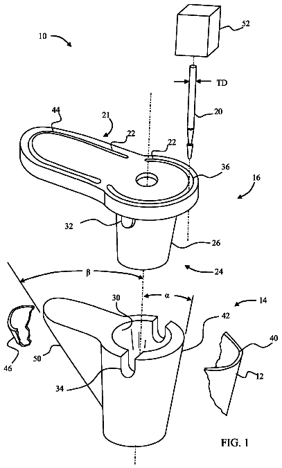
FIG. 1 is a view of a fractured humerus, with a stemmed humeral component and head inserted into a canal within the humerus;
FIG. 2 is a view showing the fin clamp and a sleeve for positioning a humeral stem provisional within a canal in the humerus;
FIG. 3 is a perspective view of a sleeve that is intended to be used to maintain the position of a humeral stem provisional within the humeral canal;
FIG. 4 is a perspective view of one type of fin clamp, shown from the top and front side;
FIG. 5 is a different perspective view of the fin clamp of FIG. 4, shown from the bottom and rear side;
FIG. 6 is a top view of the fin clamp of FIG. 4;
FIG. 7 is a front view of the fin clamp of FIG. 4 attached to a humeral stem provisional, and including a scale to show the zero point;
FIG. 8 is a view similar to FIG. 2, except this figure shows the two version pins used to test the range of motion;
FIG. 9 is another view similar to FIG. 2, except this figure shows the ruler in place, and the driver being used to insert a fixation pin into the bone;
FIG. 10 is a perspective view of the ruler of FIG. 9;
FIG. 11 is a perspective view of the fixation pin and driver of FIG. 9, except instead of including a portion of the drill, this figure includes a T-handle;
FIG. 12 is a view of the end of the fixation pin, with an enlarged view of one of the screw threads;
FIG. 12A is an enlarged view taken within circle 12A of FIG. 12;
FIG. 13 is cut-away view of the end of the driver into which the fixation pin is inserted;
FIG. 14 is a front view of the fin clamp of the earlier figures, which creates the same predetermined distance whether used for the right humerus or the left humerus;
FIG. 15 is a front view of a second fin clamp, which creates different predetermined distances for the right humerus and the left humerus; and
FIG. 16 is a front view of a third fin clamp, which creates different predetermined distances for the right humerus and the left humerus that are reversed from those of the in clamp shown in FIG. 15.
Detailed description of the invention
The present invention relates to a system of components used for properly positioning the stemmed humeral component of a shoulder prosthesis, and/or to positioning the humeral stemmed provisional, as well as to the methods of using those positioning components. The system includes one or more fin clamps, version pins, a specially configured ruler, one or more sleeves designed to be attached to the humeral stemmed provisional, a fixation pin and a driver for the fixation pin.
FIG. 1 shows one example of a stemmed humeral component 10 inserted within a humerus that has suffered a classic four-part fracture. In a four part fracture, bone has fractured into the following four parts--the lesser tuberosity 14, the greater tuberosity 16, the humeral shaft 18, and the humeral head (not shown). During shoulder arthroplasty, the stemmed humeral component 10, including a humeral head 20 (which may be a separate component or may be integrally formed with the humeral component), is implanted into a canal that is naturally found in the humeral shaft 18 (if necessary, the humeral canal may be enlarged), and the lesser and greater tuberosities (14 and 16) are refitted and secured around the stemmed humeral component 10 in locations as close as possible to their original anatomical positions. It should be noted that although the present specification shows and describes only one example of a type of stemmed humeral component and provisional, it is contemplated that the present invention could also be applied to stemmed humeral components and provisionals of many different configurations.
In order for the shoulder prosthesis to mimic the original range of motion of the shoulder joint, it is very important for all of the components of the prosthesis to be properly positioned. The present invention relates to positioning the stemmed humeral component, as well as to positioning a humeral stem provisional, the stem of which is configured to match the permanent stemmed humeral component. As known in the art, the humeral stem provisional is temporarily placed in position in the humeral canal prior to permanently positioning the permanent stemmed humeral component.
Turning now to FIG. 2, one example of a humeral stem provisional 22 is shown inserted into a canal within a left humeral shaft 18. Since the provisional itself and the process of enlarging the humeral canal (if necessary) are not part of this invention, and also since different types of provisionals and several prior art methods of enlarging the humeral canal are known, these aspects will not be discussed in detail, except as necessary for understanding the present invention. Further, for ease of description, the implants, tools and procedures shown and described will normally only be described for use with the left shoulder. However, one of ordinary skill in the art can easily apply and modify, where necessary, the implants, tools and procedures for use with the right shoulder. As can be seen in FIG. 2, the humeral stem provisional 22 in this example includes a stem 24, a collar 26, and four fins that extend radially outwardly of the stem--a medial fin 28, a lateral fin 30, an anterior fin 32, and a posterior fin 33 (shown in FIG. 1) that is a mirror image of the anterior fin 32. The collar 26 of the provisional 22 has a proximal side 34 and a distal side 36.
Seated upon the stem 24 is a sleeve 25, which is preferably made of foam or other compressible material. The sleeve 25 serves to maintain the humeral stem provisional 22 in position during intraoperative assessment of its axial height and version. In other words, because the stem provisional 22 is not cemented or otherwise rigidly held in place, it may move from the intended position. However, by attaching the sleeve 25 to the stem 24 prior to insertion of both into the canal located within the humeral shaft 18, the position of the provisional 22 is maintained. Although the sleeve 25 helps to maintain the provisional 22 in position, the addition of the sleeve 25 to the stem 24 of the provisional 22 does not create such a tight fit that the provisional cannot be moved at all. Thus, even with the sleeve 25 in place, the position of the provisional 22 can be adjusted, if necessary. However, the sleeve 25 provides a tight enough fit within the humeral canal to prevent unintended movement of the provisional 22 within the canal.
Turning now to FIG. 3, a perspective view of a preferred embodiment of the sleeve 25 is shown. Basically, the sleeve 25 is cylindrical in shape, and is preferably made of foam or other similar material. Preferably, the sleeve 25 is manufactured by stamping multiple hollow cylindrical-shaped sleeves from a flat sheet of foam (i.e., by axially stamping the sleeves). Alternatively, the sleeve 25 may be manufactured by rolling a flat, rectangular piece of foam into the hollow cylindrical shape shown, with the rolled edges being glued or otherwise affixed together along an axial line 39. Other methods of fabrication are also contemplated, such as injection molding, in which case the cylindrical shape can be directly formed. In order to provide better gripping upon the stem, as well as to make the sleeve suitable for use with stems of different diameters, four slits 40 are provided to run axially along the sleeve's inner periphery 42. The slits 40 are preferably between 1 mm and 2 mm in depth, although other depths are also contemplated. Although four slits are shown in this example, a different number of slits may also be used, or the slits may be omitted entirely, if desired.
The sleeve 25 also preferably includes a tether 44 that is attached via a hole 46 formed within a sidewall of the sleeve 25. In most cases, the to tether will not be used because the sleeve 25 will remain attached to the stem 24 of the provisional 22 when the provisional is removed from the humeral canal. However, if the sleeve somehow slips off of the provisional 22, the tether 44 may be used to pull the sleeve 25 out of the humeral canal. Thus, the tether should be long enough to extend out of the humeral canal, with sufficient length for gripping. For example, in the preferred embodiment, the tether extends from the hole 46 about eight inches. Of course, the length of the tether may be varied to be longer or shorter, if desired.
The tether 44 is preferably made of suture or other strong thread, and is preferably a looped thread that has a knot 48 near the looped end 49. To secure the tether 44 to the sleeve 25, the looped end 49 is passed through the hole 46 until it extends out through the end of the sleeve 25. Then the free end 50 and the knot 48 are passed through the looped end 49, and the free end is pulled to tighten the tether. Of course, other methods of attaching the tether to the sleeve are also contemplated.
Preferably, the sleeve 25 will be available in a variety of sizes because there are a variety of sizes of humeral stem provisionals. Thus, for example, there may be a different sized sleeve for each different size of humeral stem provisional. However, in order to reduce the number of different sizes of sleeves that need to be stocked, each sleeve can preferably be configured to be used with several differently sized provisionals. For example, if humeral stem provisionals are available in thirteen different sizes, only four different sizes of sleeves are preferably needed, with each sleeve being able to fit three or four differently sized provisionals. The following chart provides a helpful example of how the sleeves can be sized:
TABLE-US-00001 INTERIOR EXTERIOR DIAMETER OF DIAMETER INTERIOR SLEEVE STEM OF DIAMETER OF (INCLUDING DIAMETER OF SLEEVE SLEEVE TWO SLITS) PROVISIONAL 12 mm 6 mm 8 mm 6 mm-8 mm 16 mm 9 mm 11 mm 9 mm-11 mm 20 mm 12 mm 15 mm 12 mm-14 mm 24 mm 16 mm 20 mm 15 mm-18 mm
As indicated in the chart above, for thirteen different provisional sizes with stem diameters between 6 mm and 18 mm (in 1 mm increments), only four different sleeves are needed because a 6 mm interior diameter sleeve fits provisionals with stems of diameters between 6 mm and 8 mm; a 9 mm interior diameter sleeve fits stems between 9 mm and 11 mm; a 12 mm interior diameter sleeve fits stems between 12 mm and 14 mm, and a 16 mm sleeve fits stems between 15 and 18 mm. One reason that the sleeves can be used with provisionals of different sizes is that the four slits 40 allow the inner diameter of the sleeves to slightly adjust to accommodate the different diameter stems of provisionals of different sizes. As shown in the chart, a sleeve with a 12 mm exterior diameter has an interior diameter of 6 mm (in the area without any slits), but it has an interior diameter of 8 mm in the area with two of the slits because each slit is 1 mm in depth (thereby the diameter is increased by 2 mm because the two slits face each other). Likewise, the slits in the 16 mm exterior diameter sleeve are also each preferably 1 mm in depth. The slits in the 20 mm exterior diameter sleeve are each preferably 1.5 mm in depth, and the slits in the 24 mm exterior diameter shaft are each preferably 2 mm in depth. Additionally, the axial length of all of the sleeves can be the same. For example, the axial length of each sleeve is preferably between 20 and 40 mm. Of course, the dimensions mentioned above, and in other parts of this specification, are only examples of suitable dimensions, and other appropriate dimensions can be determined by those of ordinary skill in the art.
For ease of identification to distinguish the differently sized sleeves from one another, each of the sizes can be made of a different color, if desired. Accordingly, since there are four different sizes of sleeves in the example above, four different colors of foam would be used to produce the sleeves. However, since the most likely instances of confusion arise between sleeves that are only slightly larger or slightly smaller than each other, it may only be necessary to use two different colors, alternating between the two colors as the sleeves increase in size. For example for a set of four sleeves of exterior diameters of 12 mm, 16 mm, 20 mm and 24 mm, the 12 mm and 20 mm sleeves could be of a first color, and the 16 mm and 24 mm sleeves could be of a second color that is different from the first color. Such a system works because it is unlikely that someone would be confused between the 12 and 20 mm sleeves or between the 16 and 24 mm sleeves. By only using two colors instead of four, manufacturing costs are reduced.
Turning back to FIG. 2, another important aspect of the present invention will be described--fin clamp 60. Fin clamp 60 is preferably made of stainless-steel or other metal, but other materials, such as plastic, may also be used. As described more fully below, the fin clamp 60 is used to properly position the stemmed humeral component (and the humeral stem provisional) with regard to both its axial height and its retroversion. Axial height positioning will be discussed first. FIG. 7 shows one example of a fin clamp 60 attached to a stemmed humeral component 10, which is shown alongside a measurement scale. In the preferred embodiment, the zero point of the scale is taken as the point where the center axis of the stem 24 meets the distal side 36 of the collar 26. This zero point, and the rest of the numbering scale, is the same one currently used on other tools and templates in the Bigliani/Flatow.RTM. Shoulder Arthroplasty System, manufactured by Zimmer Inc. of Warsaw, Ind. However, it is not necessary to use the same scale as the Bigliani/Flatow.RTM. System, and other measurement systems and/or zero points may be used instead of those described.
Analysis has shown that in most fracture situations, the distal side 36 of the provisional's collar 26 should be spaced a certain distance from the proximal surface 38 of the humeral shaft 18. (Of course, since the relevant portions of the provisional are sized and shaped identically to those of the permanent stemmed humeral component, the collar of the permanent component, as well as the other portions of the permanent component, should be positioned identically to those of the provisional.) More specifically, in most average sized adults, it has been found that in four-part fracture scenarios, the fractured joint is best rebuilt by positioning the stemmed humeral component so that there is 18 mm of space separating the distal side 34 of the collar 26 (at the anterior fin) from the proximal surface 38 of the humeral shaft 18. However, in certain cases, the appropriate spacing is either slightly less or slightly greater than 18 mm. For example, certain situations require a 15 mm space and other cases require 21 mm of space. Accordingly, as described below, the preferred embodiment of the invention includes a set of fin clamps that are configured to provide spacing of the following predetermined distances: 15 mm, 18 mm, and 21 mm, in order to obtain the proper spacing in a variety of different situations. However, the invention is not limited to these sizes.
First, fin clamp 60, which provides 18 mm spacing, will be described. The fin clamp 60 is configured to be attached to the anterior fin 32 of the humeral stem provisional 22, as shown in the exploded view of FIG. 2. Likewise, because the stemmed humeral component 10 has essentially the same configuration as the provisional 22, the fin clamp 60 is also configured to be attached to the anterior fin of the stemmed humeral component in the same manner as attached to the provisional.
As shown in FIGS. 2, 4, 5 and 6, the fin clamp 60 includes a head 62 and an arm 64. The head 62 is configured to be seated upon the anterior fin 32 so that the head 62 is positioned between the proximal end surface 38 of the humerus 18 and the distal side 36 of the collar 26. In this embodiment, the head 62 separates the proximal end surface 38 of the humerus from the distal side 36 of the collar 26 by 18 mm. This embodiment of the fin clamp 60 is called the "universal" fin clamp because it can be used in most situations and because it can be used on either the left humerus (as shown in FIG. 2) or on the right humerus, with the separation distance for each side being the same (18 mm). Other embodiments of the fin clamp, which will be described below, are also configured to be used on either the left humerus or the right humerus, but in these other embodiments, the separation distances are not the same for both sides.
The head 62 includes a channel 66 (best seen in FIG. 6) that is configured to accept the anterior fin 32 of both the humeral stem provisional 22 and the stemmed humeral component 10. Preferably, the channel 66 is just slightly deeper than the radial length of the anterior fin 32, and is defined from side-to-side between an endblock 67 and a wall 69. An attachment arrangement that includes one or more setscrews is provided in order to attach the fin clamp 60 to the anterior fin 32. More specifically, the preferred embodiment includes two threaded holes 68, 70 (best shown in FIG. 5) that extend through the wall 69, and two setscrews 72, 74, with one setscrew being seated in each threaded hole. If desired, only one setscrew may be provided for both holes, in which case the user simply inserts the single setscrew into the appropriate hole. Preferably, the setscrews include sharp pointed tips for providing more secure attachment to the fin.
In order to attach the fin clamp 60 to the anterior fin 32, one of the setscrews (72 or 74) is tightened so that it extends through the wall 69 and makes contact with fin 32. Preferably, whichever setscrew is positioned on the proximal side will be tightened because easier access is provided for that one. Thus, if the fin clamp 60 is being used during left shoulder arthroplasty, setscrew 74 is the proximal setscrew and it will be tightened, and if it is being used during right shoulder arthroplasty, setscrew 72 is the proximal one, and it will be tightened.
The fin clamp's head 62 includes two angled surfaces 76 and 78, as most clearly shown in FIGS. 2 and 4, which are symmetric to each other and which correspond to the angle of the distal side 36 of the collar 26 of the humeral stem provisional 22 and the stemmed humeral component 10 (shown in FIG. 7). Flat surfaces 80 and 82 are also included adjacent to the angled surfaces 76 and 78, respectively. These surfaces are configured in this manner so that the surgeon can easily tell that the fin clamp 60 is properly positioned (and therefore the provisional 22 or the humeral component 10 is also properly positioned) by noting when one of the angled surfaces (76 or 78) contacts the distal side 36 of the collar 26 and the opposite flat surface (either 82 or 80) contacts the proximal surface 38 of the humeral shaft. More specifically, during left shoulder arthroplasty, proper axial positioning has been obtained when angled surface 78 contacts the distal side 36 of the collar 26 and the flat surface 82 contacts the proximal surface 38 of the humeral shaft. If the universal fin clamp 60 is positioned in this manner, the desired 18 mm separation is provided. For ease of description, the invention is being described and shown as applied to a left humeral stem provisional only (as well as to a left stemmed humeral component only). However, the universal fin clamp 60 can also be used with a right provisional or right humeral component if the fin clamp is flipped so that the opposite angled surface is the one making contact with the collar of the provisional (or humeral component).
In order to facilitate obtaining the proper orientation of the fin clamp 60, markings indicating the proper orientation of the fin clamp are preferably provided. Different markings need to indicate the proper orientation for use during left shoulder arthroplasty and during right shoulder arthroplasty, because the orientation of the fin clamp is not the same for each side. One example of such markings is shown in FIG. 7, which includes the markings L18 and R18. These markings indicate that this fin clamp provides 18 mm separation distance, and they also show the proper orientations of the fin clamp when used on either the left shoulder or the right shoulder. More specifically, in this example, when the fin clamp is used during an operation on the left shoulder, the designation L18 is upright (as shown in FIG. 7), and when used during an operation on the right shoulder, the designation R18 is upright. Of course, other types of markings may also be used, or the markings may be omitted entirely, if desired.
Turning now to FIGS. 15 and 16, two additional embodiments of the fin clamp will be described. The fin clamps of FIGS. 15 and 16 are used for creating predetermined separation distances other than the 18 mm distance described above with regard to fin clamp 60. FIG. 15 shows fin clamp 60' and FIG. 16 shows fin clamp 60''. FIG. 14, which shows the first embodiment, fin clamp 60, has been provided in order to easily compare the configurations of fin clamps 60' and 60'' with that of fin clamp 60. Fin clamps 60' and 60'' are essentially the same as fin clamp 60, except that they provide different separation distances than fin clamp 60. Additionally, fin clamps 60' and 60'' are not symmetric about their respective central axis, as fin clamp 60 is.
More specifically, fin clamp 60' of FIG. 15 is configured to provide a separation distance of 15 mm when used during left shoulder arthroplasty, as designated by the marking "L15," and to provide a separation distance of 21 mm when used during right shoulder arthroplasty, as designated by the marking "R21" (which is nearly upside-down in FIG. 15). As with the universal fin clamp 60, which has designations L18 and R18, the surgeon can tell which direction the clamp should be oriented and the separation distance created by the clamp by looking at the designations L15 and R21. More specifically, with fin clamp 60', when this fin clamp is used during an operation on the left shoulder, the designation L15 should be upright (and a 15 mm separation will be provided), and when used during an operation on the right shoulder, the designation R21 should be upright (and a 21 mm separation will be provided).
Fin clamp 60'' of FIG. 16 merely provides the opposite to configuration to that of clamp 60' of FIG. 15. Thus, fin clamp 60'' can provide a 21 mm separation distance during left shoulder arthroplasty, and it can provide a 15 mm separation during right shoulder arthroplasty. More specifically, with fin clamp 60'', when this fin clamp is used during an operation on the left shoulder, the designation L21 should be upright (and a 21 mm separation will be provided), and when used during an operation on the right shoulder, the designation R15 should be upright (and a 15 mm separation will be provided).
In order to allow the surgeon to be able to accommodate situations where any one of the three different separation distances (15 mm, 18 mm and 21 mm) is to be provided, a system, or kit, that includes several different fin clamps should be provided. More specifically, in the preferred embodiment of the kit or system, three different fin clamps are provided--fin clamp 60, fin clamp 60' and fin clamp 60''. Accordingly, with the kit, the most commonly desired separation distances can reliably be obtained.
As mentioned above, in addition to obtaining the correct axial spacing, the present invention also provides a way to set the proper retroversion of the humeral stem provisional and the stemmed humeral component. Turning now to FIG. 8, the humeral stem provisional 22 is shown seated within a canal in the left humerus 12, and the fin clamp 60 has been secured to the anterior fin by tightening the setscrew 74.
The first step for obtaining the proper retroversion of the provisional 22 and/or the humeral component 10 relates to aligning the arm 64 with respect to the approximate position of the bicipital groove in an intact humerus (FIG. 1 shows a bicipital groove 92), if clear evidence of the groove is still available. If the bicipital groove cannot be located, the surgeon may simply estimate its position, and align arm 64 with that estimation, or slightly posterior to the estimated position of the groove.
FIG. 6 shows that the arm angle is preferably 55 degrees from the anterior fin 32 (and 55 degrees from the axial stem of the humeral component 10 and the provisional 22, when the fin clamp is attached thereto). Designing the arm 64 of the fin clamp 60 to be at the 55 degree angle to align with the bicipital groove has several advantages. The fracture line between the lesser tuberosity 14 and the greater tuberosity 16 typically occurs either in line with, or slightly posterior to, the bicipital groove 92, as shown in the FIG. 1 example. Because the 55 degree angle aligns the arm 64 of the fin clamp with this fracture line, the arm 64 does not interfere with the surgeon's task of reorienting the tuberosities to confirm the position of the provisional 22 and/or the humeral component 10 while the fin clamp is attached to the provisional or the humeral component. In addition, with the arm 64 of the fin clamp configured at this angle, the arm does not interfere with a range of motion analysis.
The second step for obtaining the proper retroversion involves the use of two version pins. In FIG. 8, two version pins 84 and 86 are shown inserted into two version pin holes 88, 90, respectively (the version pin holes are also shown in FIG. 4, without the version pins inserted therein). Turning now to FIG. 6, version pin hole 88 is set to be 20 degrees from channel 66 (which sets it at 20 degrees from the anterior fin 32 and 20 degrees from the axial stem of the humeral component 10 and the provisional 22, when the fin clamp is attached thereto). In a similar manner, version pin hole 90 is set to be 40 degrees from channel 66 (and 40 degrees from the anterior fin and the axial stem of the humeral component 10 and the provisional 22, when the fin clamp is attached thereto). When the two version pins 84 and 86 are seated within the appropriate version pin holes 88 and 90, as shown in FIG. 8, the retroversion of the provisional 22 or the humeral component 10 can be tested by extending the patient's arm to make sure that the patient's forearm is centered between the version pins 88 and 90. To avoid confusion regarding the use of version pin holes 88 and 90, it is desirable to have them marked with degree indications "20" and "40," as shown in FIG. 4. However, such markings are not required. It should be noted that the 20 and 40 degree orientations of the version pins and the 55 degree stem angle shown and described are intended to be used for guidance to obtain proper retroversion. In certain situations, proper retroversion, as discovered during a range of motion analysis, will differ from these guidelines.
Once the proper axial height and the version of the provisional 22 has been established, and the provisional is located in the desired position, it is useful to mark that position to facilitate the placement of the permanent stemmed humeral component 10 into the exact same position. The present invention includes the following tools for marking the position--a specially configured ruler that can be attached to the arm of the fin clamp and a fixation pin and pin driver for temporarily inserting the pin into the humerus at a desired location along the scale of the ruler.
FIG. 9 shows one example of a specially configured ruler 94 attached to the arm 64 of fin clamp 60, with fixation pin 96 being inserted into a slot (or elongated hole) 95 in the ruler via a pin driver 98 that is attached to a rotary drill 100. Preferably, the ruler 94, the fixation pin 96 and the driver 98 are all made of stainless steel, or other metal, although other materials are also contemplated.
Briefly, in order to mark the location of the provisional, the ruler 94 is attached to the fin clamp's arm 64, and the fixation pin 96 is temporarily driven into the humerus 18 at a position within the ruler's slot 95, and the position of the pin with respect to the ruler is noted. Then, the provisional 22, the fin clamp 60 and the ruler 94 are removed, but the fixation pin 96 remains in place in the humerus. The permanent stemmed humeral component is inserted into the humerus, and the fin clamp 60 and ruler 94 are attached thereto, as they were attached to the provisional. The position of the assembly of the permanent stemmed humeral component, the fin clamp and the ruler is adjusted until the fixation pin is positioned at the same spot within the slot on the ruler that was previously noted. Thus, by using the fin clamp, the ruler and the fixation pin (and pin driver)--the version and height of the provisional can be been duplicated for the permanent humeral component.
The description continues in the full USPTO document.
 Lapsed, fee not paid15 drawings