 Lapsed, fee not paid1 drawing
Industrial Equipment · US 8,544,355 B2
Parking lock arrangement
A parking lock arrangement for a motor vehicle gearbox.
US 8,544,454 B2 · Assignee: Behr GmbH & Co. KG · Inventors: Geskes; Peter et al.
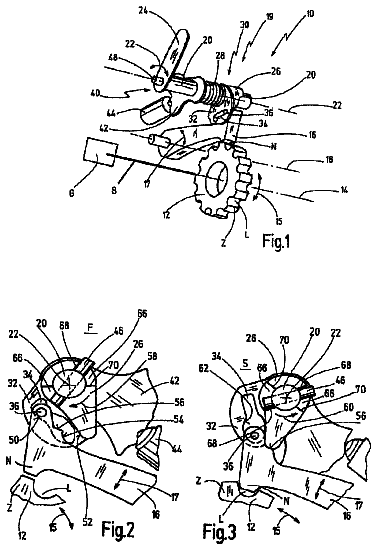
Sheet 1 of 19 from the published document. All sheets in the USPTO PDF
The invention relates to a heat exchanger (or a motor vehicle, comprising a first flow path (1) with a number of flow conduits (6) for conducting a fluid to be cooled, a deflection region (13), situated downstream of the first flow path (1) and a second flow path (2), situated downstream ol the deflection region (13). According to the invention, the flow conduits (6) of the first flow path (1) continue in the deflection region (13) and the second (low path (2) as continuous separate flow conduits (6). The invention also relates to a flow conduit (41, 41', 61, 61', 71, 71', 81, 81', 91, 91') for a heat exchanger (30,40) for exchanging heat between a first fluid (31) and a second fluid (33). The aim of the invention is to guarantee an improved transfer of heat with a simultaneous acceptable pressure drop, whilst reducing the blocking risk.
1 of 19 drawing sheets so far from the published document, cropped to the drawing. Every sheet is in the USPTO PDF.
What the patent claimed, word for word. All of it is now free to use.
The present invention relates, in a first variant, to a heat exchanger for a motor vehicle.
In a second variant, the invention also relates to a flow duct for a heat exchanger for an exchange of heat between a first fluid and a second fluid, having: a duct casing having an interior space which is surrounded by a duct casing inner side; a number of webs arranged in the interior space on the duct casing inner side, which flow duct has a cross section, which is designed for conducting the first fluid in the interior space and which can be traversed by flow, transversely with respect to a flow duct axis. The invention also relates to a heat exchanger for an exchange of heat between a first fluid and a second fluid, having: a block for the separate and heat-exchanging guidance of the first and second fluids, and a fluid connection for the first fluid; which block has a housing with a chamber which can be traversed by the second fluid and a block closure element for the preferably fluid-tight separation of the chamber and the fluid connection. The invention also relates to an exhaust-gas recirculation system, to a charge-air supply system and to a use of the heat exchanger.
In the construction of heat exchangers for motor vehicles, increasing demands are being made on the exchanger power for a limited installation space. In the case in particular of the cooling of exhaust gas for the purpose of recirculation to an internal combustion engine, it is also necessary here to overcome large temperature differences.
It is the object of the invention according to the first variant to specify a heat exchanger for a motor vehicle which has a high exchanger power for a limited installation space, with cost-effective production.
The flow duct specified in the introduction for use in a heat exchanger is known from DE 37 316 69 A1 from the applicant.
Heat exchangers of the type specified in the introduction have the task of cooling a hot first fluid by means of a relatively cold second fluid, in order that the first fluid, in particular an exhaust gas or exhaust-gas/air mixture or charge air can be admixed to the intake air for an internal combustion engine, for example of an engine. The second fluid may be a coolant, for example a liquid or gaseous or mixed liquid-gas coolant which can, at any rate in the case of a liquid coolant, be extracted from the cooling circuit of the internal combustion engine. It is fundamentally sought, in order to increase a thermodynamic efficiency, that the cooling takes place to as low a temperature level as possible. It is known that the concept of cooled exhaust-gas recirculation or cooled charge air can serve to reduce pollutants, in particular nitrogen oxides, in the exhaust gas.
With regard specifically to the demands of modern-day engines, it is possible by means of exhaust-gas recirculation coolers to meet the ever increasing demands on exhaust-gas purification. By cooling the exhaust gas and re-supplying the cooled exhaust gas, the combustion temperature in the engine is lowered and leads to reduced NO.sub.x emissions. Increasing demands on pollutant reduction result in the further development of known cooler concepts and the proposal of new cooler concepts.
A flow duct in a heat exchanger of known type may be produced from a steel or high-grade steel material. Here, the corrosion resistance of steel and high-grade steel materials has been proven in particular.
It has also been found that flow ducts composed of aluminum or based on an aluminum material can be produced in a very cost-effective manner.
In order to sufficiently improve an exchange of heat in a flow duct, a flow duct is generally fitted, as explained in the introduction, with a number of webs arranged in the interior space on the duct casing inner side. The number of webs can fundamentally contribute to an increase in the exchange of heat. However, if an excessive number of webs are used, the risk of blockage by soot particles, which are for example contained in the exhaust gas, increases considerably. It has been found that, where excessively narrow passage regions, which are defined substantially by the cross section which can be traversed by flow, are provided in the flow duct, a flow duct becomes contaminated comparatively quickly and, in the worst case, can become partially blocked. This process, as well as further measures for increasing an exchange of heat, also adversely increase the pressure loss generated in a flow duct, which is undesirable in the context of modern heat exchanger concepts.
In addition to the design of a flow duct disclosed in DE 37 316 69 A1 with an extruded duct casing, there are further types of design, as are known for example from DE 10 225 812 C1, G 94 065 59.4, DE 36 153 00 C2 and DE 202 05 200 U1. However, flow ducts specified in said documents are intended and designed specifically for a particular application. For example, U.S. Pat. No. 5,184,672 discloses a flow duct for a heat exchanger in the form of a condenser which is fitted with flat tubes through which a liquid coolant flows. U.S. Pat. No. 3,486,489 discloses an oil cooler which is fitted with flat tubes through which oil to be cooled flows. US 2005/0061488A1 discloses a heat exchanger which is designed for cooling oil and whose flow ducts are designed for conducting the oil to be cooled. The cross section, which can be traversed by flow, of the flow ducts described therein is designed specifically for being traversed by oil. In US 2005/0061488A1, the cross section which can be traversed by flow is characterized by a power ratio of between 3.9 and 8.5, which is defined as a ratio of a wetted periphery in mm to a traversable cross-sectional area of the metal tube in mm.sup.2.
Such flow ducts which are designed for conducting liquid fluids are not suitable for use in a heat exchanger of the type specified in the introduction. The heat exchanger of the type specified in the introduction is designed in particular as an exhaust-gas heat exchanger and/or as a charge-air heat exchanger. In this case, the first fluid is gaseous or a vapor, that is to say for example an exhaust gas or an exhaust-gas/air mixture or charge air. In this case, the second fluid is a coolant, in particular a liquid or gaseous or mixed liquid-gas coolant. With regard to the problems explained above, it is desirable to realize an improved design concept for a flow duct.
The second variant of the invention addresses this; it is the object of said second variant to specify a flow duct which has an improved exchange of heat. Furthermore, it is sought in particular that an acceptable pressure loss can be obtained and in particular that a risk of blockage is reduced. It is also an object of the invention to specify an advantageous concept for an exchange of heat and an exhaust-gas recirculation system and a charge-air supply system and an advantageous use of the heat exchanger.
The object is achieved according to the invention, for the heat exchanger specified in the introduction according to the first variant. By means of the continuous design of the flow ducts which are separate from one another, it is possible to construct a so-called U-flow heat exchanger which ensures a good exchange of heat between the fluid conducted within the flow ducts and the exterior of the flow ducts even in its deflecting region, in contrast to previous known designs. Furthermore, a heat exchange of said type can be produced in a cost-effective and simple manner.
In one preferred embodiment, the fluid is exhaust gas of an internal combustion engine of the motor vehicle. The particular object of cooling generally very hot exhaust gas can be achieved particularly effectively by means of a heat exchanger according to the invention since said heat exchanger has a very high heat exchanger power for a given installation space. In addition, the separate, continuously guided flow ducts in the deflecting region can, in contrast to known solutions from the prior art, be thermally insulated particularly effectively with respect to surrounding parts of the vehicle, for example by means of a coolant-conducting outer housing. Alternatively, the fluid of the heat exchanger according to the invention may however also be charge air of an internal combustion engine of the motor vehicle or else lubricating oil from a lubricating oil circuit of the motor vehicle, or some other fluid to be cooled of the motor vehicle.
To obtain a simple design, the flow ducts are preferably fixed at the end side to a base element, with in each case both ends of the continuous flow ducts opening out in the base element.
Particularly effective cooling of the fluid can be obtained in that the flow ducts are arranged in a housing which can be traversed by an in particular liquid coolant. Here, the housing advantageously has an inflow and an outflow for the coolant, with one of the two, inflow or outflow, being arranged in the vicinity of the deflecting region of the flow ducts, in particular in the vicinity of an apex of the deflecting region. In this way, it is possible in a simple manner to obtain as complete and uniform a flow of coolant around all of the flow ducts as possible. To further improve the flow around said flow ducts, a guide element for guiding the coolant can preferably be arranged in the housing. Guide elements of said type can direct the flow to certain regions and/or can generate turbulence in the coolant.
It is also preferable for support means for holding the flow ducts to be arranged in the housing in order to limit vibration amplitudes of the flow ducts and to thereby prevent cracks from forming even in the event of intense vibrations. Because the support means are situated in a housing in liquid coolant, said support means may also be composed of a thermally undemanding material such as plastic in order to save on costs.
It is generally provided in order to save on production costs that the housing is composed substantially of a plastic.
To reduce production costs and to realize complex cross-sectional shapes in a simple manner, a flow duct is advantageously formed as an extruded profile. Here, at least two flow ducts are particularly advantageously provided within one extruded profile, with the extruded profile having an outer wall, around which coolant flows, and an inner wall which separates the flow ducts from one another. In this way, it is possible in a cost-effective and functionally reliable manner to provide a large contact area between the fluid and the heat-exchanging material of the flow duct. Here, the outer wall particularly preferably has, in cross section, an at least partially rounded profile for the purpose of better bendability. By means of said shaping, it is possible to provide an initially linearly-extruded extruded profile, in a further production step, with a sufficiently tightly curved deflecting region which is usually formed as a 180.degree. bend piece. Alternatively, or in addition, it is possible for the inner wall, at least in a non-bent state of the extruded profile, to have a thickness which varies over its length, with in particular a thin region being assigned to a small bend radius. It is likewise possible in this way to improve the bendability of the bundle of flow ducts. Such complex designs of a cross-sectional shape do not entail any particular expenditure specifically when using extruded profiles. Here, the thickness ideally increases outward from 0.2 . . . 1.5 mm by 1.2 to 2 times.
A plurality of extruded profiles are generally preferably provided in order to ensure an effective exchange of heat between the coolant and flow ducts.
The extruded profile is advantageously composed of an aluminum-based alloy. Aluminum has extremely good corrosion resistance and can be extruded in a cost-effective manner in almost any desired cross-sectional shapes. Where sufficient cooling is provided, aluminum may by all means be used in the construction of exhaust-gas heat exchangers.
In one preferred detail design, one of the flow ducts is an outer flow duct and another of the flow ducts is an inner flow duct, with the inner flow duct having a smaller deflection radius than the outer flow duct in the deflecting region. Here, the inner flow duct particularly preferably has a greater wall thickness than the outer flow duct, such that, overall, weight and material quantity are optimized with regard to the mechanical demands during the production of the heat exchanger, and in particular during the bending of the flow ducts.
To improve the exchanger power for a given installation size, turbulence-generating means are advantageously provided in at least one of the flow ducts. The turbulence-generating means particularly preferably vary over a course of the flow duct, with in particular a flow resistance increasing over the course of the flow duct. This permits fine-tuning of the exchanger power taking into consideration that the temperature difference between the fluid and surrounding coolant decreases over the course of the flow path, such that an optimum adaptation of the exchanger power per unit length of the flow duct is positively associated with a variation in the flow resistance or the proportion of turbulence generated in the fluid flow. Such an adaptation can consist even in providing different turbulence-generating means in the region of the first flow path than in the region of the second flow path and/or in the deflecting region.
In an alternative embodiment, a flow duct has two straight sections of a tube, with a bend piece being connected to the two straight sections an in the deflecting region. Depending on the type and material of the flow ducts, it is possible to simplify production in this way.
The flow ducts generally preferably have a corrosion-inhibiting coating. Such coatings are expedient in particular in the event of the heat exchanger being designed as an exhaust-gas heat exchanger, in order to lengthen the service life of the heat exchanger.
Furthermore, at least one flow duct of the first flow path can bear adjacently against a flow duct of the second flow path in the deflecting region, with the deflecting region being designed as a separate element which is placed on ends of the two flow ducts in order to connect them. For inner flow ducts in particular, with a correspondingly small deflecting region, this offers a space-saving solution with simultaneously relatively small wall thicknesses. Furthermore, the spacing between flow ducts which are adjacent to one another in the connecting region can in this way be designed to be particularly small, which leads overall to a small design of the heat exchanger.
In one preferred embodiment, in at least one of the flow ducts, at least in a non-bent state, an inner wall in relation to a bend in the deflecting region has a smaller wall thickness than an outer wall in relation to the bend. In this way, it is possible to obtain a particularly tight bend radius in the deflecting region. The wall thicknesses of the outer bend region are preferably 1.2-2 times, but at best 1.5 times, those of the inner wall region in the bend. Here, the wall thickness in the inner bend radius should preferably be in the region of 0.42 mm, ideally approximately 1 mm.
In a further preferred design, a first continuous flow duct runs in a first plane, with a second continuous flow duct intersecting the plane in particular in the deflecting region. Here, the first flow duct and the second flow duct have in particular a different length. It is possible by means of this measure, too to reduce an empty intermediate space, which does not contribute to the exchanger power, between adjacent flow ducts, such that the installation size is reduced overall for a given exchanger power.
The use of extruded profiles to form the flow ducts very generally permits cost-effective production, wherein, as a result of the large degree of freedom in the cross-sectional shaping of extruded profiles, it is possible in a simple manner to provide flow ducts with a good exchange of heat between fluid to be cooled and an outer coolant. These advantages fundamentally also apply to heat exchangers of straight design or of some other design than U-flow design.
The object relating to the flow duct is achieved by means of a flow duct of the type specified in the introduction in which is provided, according to the invention, a hydraulic diameter, defined as four times the ratio of the area of the cross section which can be traversed by flow to a periphery wetted by the first fluid, which is in a range between 1.5 mm and 6 mm.
The invention is based on the consideration that, in a flow duct according to the concept of the invention, a certain range with respect to the hydraulic diameter should not be exceeded or undershot. The invention has recognized that, in the event of the hydraulic diameter being selected, for example, to be too large, a passage for the first fluid, in particular an exhaust gas or exhaust-gas/air mixture or charge air, is duly large enough to avoid blockage problems or significant contamination problems, or if appropriate to keep the pressure loss low. However, in the event of a hydraulic diameter being selected to be too large, an exchange of heat is reduced. In the inverse case of a hydraulic diameter being selected to be too small, it is duly possible that a flow duct initially provides a sufficient exchange of heat. In such a case, however, a passage in the cross section which can be traversed by flow which is selected to be too small will become contaminated comparatively quickly, and in the worst case become blocked, but at any rate lead to an increased pressure loss, during operation. This would then lead to a considerable decrease in the heat exchanger power of a heat exchanger. Furthermore, a pressure loss will increase disproportionately in the event of parts of a flow duct becoming excessively contaminated or even blocked.
According to the concept of the invention, the range of a hydraulic diameter according to the invention has proven to be superior to known concepts. A flow duct according to the concept of the invention makes it possible to provide a sufficient exchange of heat in a heat exchanger and to nevertheless ensure an acceptable pressure loss with a simultaneously reduced risk of blockage.
In particular, it has also been proven in a flow duct according to the concept of one particularly preferred refinement of the invention that said flow duct has an increased level of corrosion resistance on account of the extruded duct casing. It is also possible to provide additional corrosion protection in a flow duct produced in this way or in some other way. The flow duct according to the concept of the invention permits an improved solution for a heat exchanger with regard to heat exchanger power, pressure loss and contamination, and simultaneously cost-saving use of comparatively corrosion-resistant materials, in particular extruded aluminum materials.
Advantageous refinements of the invention can be gathered with advantageous possibilities for realizing the above-explained concept within the context of the set problem and with regard to further advantages.
A hydraulic diameter in a range between 2 mm and 5 mm has proven to be particularly preferable for realizing the concept of the invention. The size of said range particularly advantageously realizes--as explained in detail on the basis of FIG. 5, FIG. 6, FIG. 7 and FIG. 8--a compromise between the tendency to realize as effective an exchange of heat as possible in a flow duct, and the tendency on the other hand to reduce a pressure loss, or realize an acceptable pressure loss while nevertheless providing an effective exchange of heat. In this connection, a hydraulic diameter in the range between 3 mm and 3.4 mm, in particular between 3.1 mm and 3.3 mm, has proven to be more particularly preferable. With regard in particular to the latter range of a hydraulic diameter between 3.1 mm and 3.3 mm, it has been found that a hydraulic diameter of approximately 3.2 mm is particularly expedient. Although it is fundamentally not possible in the stated range to prevent contamination of the flow duct, in particular of the heat exchanger tube, tests have however shown that, in said range, contamination of the flow duct stabilizes in such a way that a decrease in power is also kept to a comparatively low level. While it is to be expected that, in ranges of the hydraulic diameter outside the above-specified ranges, a flow duct will become increasingly contaminated the longer it is operated, it is to be assumed that, in the preferred ranges of a hydraulic diameter as specified above of proven dimensions, a pressure loss stabilizes at a comparatively low level. A possible sub-optimal heat exchanger power of a heat exchanger is not reduced further with continued operation of the heat exchanger. In ranges of a hydraulic diameter outside those stated above, however, a disproportionate increase in pressure loss, and ultimately in the worst case a blockage of the flow duct, occurs during continued operation of the flow duct.
A flow duct according to the concept of the invention can advantageously be used both within the context of high-pressure exhaust-gas recirculation, as explained in more detail with reference to FIG. 1.2, and also within the context of low-pressure exhaust-gas recirculation, as explained in more detail with reference to FIG. 2.2. Furthermore, an application for charge-air cooling is also possible. In all fields of application, in particular those stated or others, an increase in the number of webs to improve the exchange of heat is avoided, according to the concept of the invention, by virtue of the hydraulic diameter being selected in a range between 1.5 mm and 6 mm. However, it has been found in tests that an optimum selection of a range for the hydraulic diameter can be different for low-pressure exhaust-gas recirculation, high-pressure exhaust-gas recirculation or charge-air cooling. In the case of high-pressure exhaust-gas recirculation, as has been proven, both the increase in a pressure loss and also the increased risk of blockage or significant contamination of a flow duct with soot particles or the like are relatively critical. For a high-pressure heat exchanger, a range of a hydraulic diameter of between 2.5 mm and 4 mm, in particular between 2.8 mm and 3.8 mm, has proven to be particularly advantageous.
In a low-pressure exhaust-gas recirculation concept, the increase in the pressure loss has proven to be particularly critical, since said pressure loss should preferably be kept particularly low within the context of a low-pressure application. For a low-pressure heat exchanger, a range of a hydraulic diameter of between 2 mm and 3.5 mm, in particular between 2.5 mm and 3.5 mm, has proven to be particularly advantageous.
It has proven to be particularly advantageous, in particular in order to increase a level of corrosion resistance, to select a ratio of a web thickness and a duct casing thickness to be less than a value of 1.0. In other words, to increase the level of corrosion resistance, it is advantageous to provide the duct casing with a greater wall thickness than a web. This is advantageous in particular with regard to the design of a flow duct in which at least one duct casing is produced on the basis of an aluminum material.
Furthermore, it has proven to be fundamentally relevant to optimize a duct casing thickness in such a way as to firstly ensure a sufficient level of corrosion resistance, in particular in the case of a flow duct based on an aluminum material, and secondly provide a sufficient number of flow ducts in the available installation space of a heat exchanger. An installation space for a heat exchanger in an engine is usually comparatively limited, such that it falls fundamentally within the scope of an improvement to provide as many flow ducts in a heat exchanger as possible, and therefore to design a duct casing thickness not to be excessively thick. According to a particularly preferred refinement of the invention, a ratio of the hydraulic diameter and a duct casing thickness in a range between 0.8 and 8 has proven to be particularly advantageous. Said range has proven to be particularly expedient in particular in a flow duct based on an aluminum material, in particular in a flow duct in which at least the duct casing is based on an aluminum material. Also advantageous is a range between 1.2 and 6, in particular a range between 1.4 and 6, with regard to the design of the duct casing thickness (installation space requirement, corrosion resistance) and the hydraulic diameter (heat exchange, pressure loss).
The concept of the invention, and/or one or more of the above-specified refinements individually or in combination, has proven to be particularly advantageous for dimensions of a flow duct which realize a ratio of the periphery wetted by the first fluid and an outer periphery of the flow duct in a range between 0.1 and 0.5. The tests carried out in this regard have shown that, within the range of the specified dimensions, the behavior of a flow duct is particularly advantageous with regard to the above-explained problem.
A flow duct according to the concept of the invention may fundamentally be realized in numerous forms, in particular as an extruded profile. With regard to production aspects and the problem specified above, a flow duct in which a web as a full web in tube cross section is arranged at one end and at the other end on the duct casing inner side. In particular, a tube cross section may have only full webs. A full web is advantageously guided continuously, without openings, between a first duct casing inner side and a second duct casing inner side. As is explained by way of example on the basis of FIG. 9A.2 and 9B.2, it is possible in this way to realize a flow duct with a hydraulic diameter as per the concept of the invention.
Furthermore, a flow duct has proven to be advantageous in which a web as a partial web in tube cross section is arranged only at one end on the duct casing inner side and at the other end projects freely into the interior space. As explained by way of example on the basis of FIG. 10A.2 and FIG. 10B.2 and also FIG. 11A.2 and FIG. 11B.2, it is particularly advantageously possible by means of an extruded flow duct to realize a hydraulic diameter as per the concept of the invention.
It has been proven that advantageously two partial webs are arranged with opposing end sides at the other end. Alternatively, or in combination with the above-specified arrangement of partial webs, it is possible for two partial webs to be arranged with end sides which are laterally offset with respect to one another at the other end. It is preferable for a partial web and a full web to be arranged alternately adjacent to one another.
It has proven to be particularly advantageous for dimensions and arrangements of the partial webs to be arrived at as follows. According to one particularly preferred refinement, a ratio of a spacing between two partial webs, which are in particular opposite one another and/or offset with respect to one another, to a height of the tube cross section is in a range below 0.8, in particular in a range between 0.3 and 0.7. A ratio of a spacing of a first partial web to a full web to a spacing of a second partial web to the full web is preferably in a range between 0.5 and 0.9, in particular in a range between 0.6 and 0.8.
The duct casing, preferably the entire flow duct, is preferably composed of an aluminum-based material.
Alternatively, additionally or in combination, said material may also be a steel-based, in particular high-grade-steel-based material.
The duct casing may preferably be formed as a tube, in particular as a welded tube and/or soldered tube or extruded tube. A flow duct may for example be produced from a sheet-metal strip which is shaped to form a tube and which is then welded or soldered longitudinally. Furthermore, a flow duct may also be formed by disks or plates which are connected to one another. In particular, at least the duct casing, in particular the entire flow duct, is formed as an extruded profile.
In the case of an extruded flow duct based on an aluminum material, it has been proven that its corrosion-resistance properties are comparatively good. This is to be attributed inter alia to a comparatively small grain structure resulting from the extrusion, and comparatively smooth surface. This has the result that even acidic exhaust-gas condensates are opposed by a sufficient level of corrosion resistance for the demands of modern heat exchanger concepts.
According to one particularly preferred first refinement of the invention, at least one web of the number of webs, preferably all the webs, is a web which is extruded with the duct casing.
According to a particularly preferred second refinement of the invention, at least one web of the number of webs, preferably all the webs, is a web which is produced separately from the duct casing and which is connected to the duct inner side. A web is preferably further integrally formed and/or molded and/or shaped. This has proven to be particularly expedient in order to take further measures in an extruded web to attach flow-conducting elements or turbulence-generating elements. A web is preferably arranged so as to run parallel to a flow duct axis. It is however fundamentally also possible to generate, during an extrusion process, webs which run in a corrugated fashion along the flow duct axis. Primarily with regard to the configuration of an extrusion process, it has proven to be expedient to design a web to be continuous along a flow duct axis.
With regard in particular to the second refinement of the invention, it is possible for a web to be inserted, in particular pushed, into the duct casing--for example as disclosed in DE 37 316 69 A1.
A web according to the second refinement is preferably cohesively connected to the duct inner side. In particular, it has proven to be advantageous to solder, weld and/or adhesively bond a web to the duct inner side. A web produced separately from the duct casing, according to the second refinement, can be milled, punched and/or rolled.
Within the context of one particularly preferred refinement of the invention--in particular with regard to a refinement in which at least the duct casing, preferably the entire flow duct is produced on the basis of an aluminum material--it is possible to provide at least one web and/or the duct casing, preferably the duct casing inner side, with a corrosion prevention arrangement. A corrosion prevention arrangement may particularly advantageously be provided in the form of a zinc coating and/or a lacquer.
The duct casing may fundamentally be formed to be of any desired suitable shape. The duct casing is particularly preferably formed in the manner of a tube, preferably an extruded tube. Flat tubes in particular have proven to be expedient in modern designs of heat exchanger. A duct casing in the form of a tube formed by two disks which are joined to one another is also suitable. A tube cross section may fundamentally be selected to be of one of numerous possible shapes--a rectangular, oval or semi-oval tube cross section has proven to be particularly advantageous.
According to the second refinement of the invention, a web may be formed as a part of a profile with corrugated, in particular rectangularly corrugated or trapezoidally corrugated cross section. The formation of profiles of said type is particularly simple and has also proven to be particularly advantageous with regard to increasing the exchange of heat.
According to the second refinement of the invention, it is preferably possible for a number of profiles which are corrugated in cross section to be arranged in series along a flow duct axis--this is explained for example with reference to FIG. 12A.2, FIG. 12B.2 and also FIG. 13A.2, FIG. 13B.2.
A web may fundamentally have flow conducting elements and/or turbulence elements of a variety of types, wherein the design and selection of elements of said type may be carried out according to the desired purpose and use of the flow duct. Particularly advantageous is a flow conducting element and/or a turbulence element selected from the group consisting of: a number of interruptions and/or openings along a flow duct axis, in particular as punched-out portions, convexities, such as gills or the like; a number of corrugations, preferably in the flow direction; a number of web openings which are offset relative to one another, in particular offset relative to one another in the flow direction, so as to form a web fin. Exemplary possibilities are explained with reference to FIG. 14A.2, FIG. 14B.2.
In one particularly preferred refinement according to the concept of the invention, a number of 2 to 20, in particular 5 to 15, in particular 7 to 12, in particular 8 to 11, in particular 9 webs are arranged adjacent to one another so as to be distributed over a tube cross section.
With regard to the heat exchanger, the object is achieved by the invention according to the second variant by means of a heat exchanger of the type specified in the introduction, in which it is provided according to the invention that the block has a number of flow ducts according to concept of the invention, which flow ducts can be traversed by the first fluid, and with the fluid connection being flow-connected to the flow ducts. The housing preferably holds the flow ducts.
A flow duct according to the concept of the invention can advantageously be used both in a heat exchanger of the first variant of the invention and also in a heat exchanger of the second variant of the invention.
The block closure element is preferably in the form of a base with one or with a plurality of passage openings for the flow ducts.
It is preferably possible for in each case one separate, with regard to the first fluid, inlet-side and outlet-side block closure element to be provided. This is the case in particular in a heat exchanger of so-called I-flow design. Here, the first fluid is supplied to the heat exchanger at a first side and is discharged at a second side.
In addition, or alternatively, a block closure element may have an inlet region and an outlet region for the first fluid. This relates in particular to a heat exchanger of so-called U-flow design, in which the first fluid is supplied at a first side and is discharged at the same side in the opposite direction.
A fluid connection may preferably be formed in the manner of a diffuser, in particular an inlet diffuser and/or outlet diffuser.
The invention also encompasses an exhaust-gas recirculation system for an internal combustion engine, having an exhaust-gas recirculation line, a compressor and, according to the invention, a heat exchanger according to the concept of the invention in the form of an exhaust-gas heat exchanger, in particular exhaust-gas cooler.
In terms of the exhaust-gas recirculation, a fundamental distinction is made between high-pressure recirculation, as is explained in more detail by way of example with reference to FIG. 1.2, and low-pressure recirculation, as is explained in more detail by way of example with reference to FIG. 2.2. In the case of high-pressure recirculation, an exhaust-gas heat exchanger is arranged at a high-pressure side, that is to say an outlet side of an internal combustion engine.
In the case of low-pressure recirculation, an exhaust-gas heat exchanger is arranged on a low-pressure side of an internal combustion engine, that is to say is arranged upstream in particular at an inlet side of an internal combustion engine. With regard to these possibilities, reference is made primarily to the above-specified different possible configuration of a hydraulic diameter specifically for these possibilities.
The invention also encompasses a charge-air supply system for an internal combustion engine, having a charge-air intake line, an air filter, a compressor and, according to the invention, a heat exchanger according to the concept of the invention in the form of a charge-air heat exchanger, in particular charge-air cooler.
The invention also encompasses a use of the heat exchanger according to the concept of the invention for an internal combustion engine, in particular a diesel engine, of a motor vehicle, in particular of a utility vehicle or passenger vehicle.
The invention also encompasses a use of the heat exchanger according to the concept of the invention for an internal combustion engine, in particular a spark-ignition engine, of a motor vehicle, in particular of a passenger vehicle or utility vehicle.
The application of the concept of the invention to a two-stage heat exchanger has proven to be particularly preferably. The second fluid may fundamentally be a liquid coolant or a gaseous or mixed liquid-gas coolant. In one preferred application, the concept of the invention may be realized in a two-stage heat exchanger which is cooled in the first stage by means of a liquid coolant and in the second stage by means of a gaseous or aeriform coolant. A flow duct according to the concept of the invention may be used solely in the first stage of the heat exchanger or in solely the second stage of the heat exchanger or in both stages of the heat exchanger, and may be adapted with regard to the pressure and temperature conditions characteristic of the stages.
Exemplary embodiments of the invention are now explained below on the basis of the drawings. Said drawings are intended to illustrate the exemplary embodiments not necessarily to scale; the drawings are in fact shown in schematized and/or slightly distorted form where appropriate for explanation. With regard to enhancements of the teaching which can be directly gathered from the drawings, reference is made to the relevant prior art. Here, it is to be taken into consideration that various modifications and changes relating to the shape and details of an embodiment may be carried out without departing from the general idea of the invention. The features of the invention disclosed in the above description and in the drawings can be essential both individually and also in combination for the refinement of the invention. Furthermore, the scope of the invention also encompasses all combinations of at least two of the features disclosed in the description and in the drawings. The general idea of the invention is not restricted to the precise shape or the detail of the preferred embodiment shown and described below, or restricted to a subject matter which would be restricted in relation to the subject matter claimed in the claims. Where dimensional ranges are specified, values which fall within the specified limits are also intended to be disclosed as limit values and usable and claimable in any desired manner.
Further advantages and features may be gathered from the exemplary embodiments described below.
A plurality of preferred exemplary embodiments of a heat exchanger according to the invention according to the first and second variants are described below and explained in more detail on the basis of the appended drawings, wherein features of the first and second variants may be combined with and complement one another in any desired manner.
First Variant:
FIG. 1.1 is a general schematic three-dimensional illustration of a U-flow heat exchanger,
FIG. 2.1 shows a schematic plan view of a first exemplary embodiment of a heat exchanger according to the invention,
FIG. 3.1 shows a schematic plan view of a modification of the heat exchanger from FIG. 2.1,
FIG. 4.1 shows a connection-side plan view of a second exemplary embodiment of a heat exchanger according to the invention,
FIG. 5.1 shows a connection-side plan view of a third exemplary embodiment of a heat exchanger,
The description continues in the full USPTO document.
About 6,716 words. The USPTO PDF has it with every drawing.
Fees are due 3.5, 7.5 and 11.5 years after grant. This patent expired on October 1, 2025, so the fee marked "not paid" was the one that went unpaid.
HEAT EXCHANGER FOR A MOTOR VEHICLE
Filed Mar 2007 · published Apr 2009Heat exchanger for a motor vehicle
Filed Mar 2007 · granted Oct 2013Earlier publications, parents and continuations. None of them can still be enforced, or this patent would not be listed.
Prior art cited by the examiner or applicant. Useful when you check your own idea for novelty.
Everything on this page comes from the documents linked above.


