Cross reference to related application
The present application claims priority to Japanese Patent Application No. 2008-248488, which was filed on Sep. 26, 2008, the disclosure of which is incorporated herein by reference in its entirety.
Background of the invention
1. Field of the invention
The present invention relates to an automatic sheet transporting apparatus configured to separate and transport sheets stacked on a feed tray portion one by one to a discharge tray portion, and an automatic document scanning apparatus having this automatic sheet transporting apparatus and a scanning device configured to scan an image of a transported document at a scanning position. Also, the invention relates to an automatic sheet transporting apparatus configured to be capable of guiding a succeeding sheet or document to be discharged in between a sheet or document already discharged on a paper discharge tray portion and the discharge tray portion and then transporting the succeeding sheet or document smoothly, and an automatic document scanning apparatus having this automatic sheet transporting apparatus.
2. Description of the related art
In general, in an image scanning apparatus which is capable of scanning an image surface of a transported document, an image scanning device such as a CIS (Contact Image Sensor) or a CCD (Charge Coupled Device) unit is arranged on a lower surface of a document passage transparent panel (glass plate). An automatic document transporting apparatus provided in a lid-type cover member, which is openable and closable with respect to an upper surface of the document passage transparent panel, separates and transports a plurality of documents stacked on a paper feed tray portion one by one to the document passage transparent panel, then the image scanning device scans the image surface of the transported document, and then the document is discharged on a paper discharge tray portion.
A document transporting path in this case is formed into a U-shape extending from the paper feed tray portion for documents arranged on the upper side to a paper discharge tray portion arranged on the lower side via a document scanning position, which is provided in an automatic document scanning apparatus of an upper paper feeding system as shown in JP-A-2003-76074, and a type formed into an U-shape extending from the paper feed tray portion for documents arranged on the lower side to the paper discharge tray portion arranged on the upper side via the document scanning position, which is provided in an automatic document scanning apparatus known as a lower paper feeding system as shown in JP-A-2005-247575.
In the automatic document scanning apparatus of the lower paper feeding system, a plurality of documents are stacked with the image surfaces down on the paper feed tray portion, and the documents are separated and transported one by one from the lower most document to a scanner. Then, in the scanner, the documents are transported with the image surfaces opposed to an upper (front) surface of the document passage transparent panel and, when the documents are discharged to the paper discharge tray portion via the U-shaped document transporting path, are stacked thereon with the image surfaces up.
In the case of the automatic document scanning apparatus of the lower paper feeding system, when the heightwise position of a nip of a paper discharging roller pair arranged at a terminal end of the U-shaped document transporting path is higher than an upstream end of the paper discharge tray portion in terms of discharging direction, the succeeding documents are stacked on the upper surface of the previously discharged documents.
Accordingly, the order of documents stacked in the paper discharge tray portion with the image surfaces up is completely reverse from the order of the documents stacked in the paper feed tray portion. In order to arrange these documents in the original order, it is necessary to manually rearrange the document order, which may take a great deal of time and effort.
Therefore, in JP-A-2005-247575, the heightwise position of the nip of the paper discharging roller pair arranged at the terminal end of the U-shaped document transporting path is set to be lower than the upstream end of the paper discharge tray portion in terms of the discharging direction so that the succeeding documents discharged therefrom are guided to the underside of the previously discharged documents (this is referred to as "slip" under or in). Consequently, the documents are stacked on the paper discharge tray portion in the same order as the order of the documents stacked in the paper feed tray portion (hereinafter, referred to as "same order stacking").
However, if the number of documents stacked in the paper discharge tray portion is increased, the weight of the stacked documents is also increased. Then, the subsequently discharged document is subjected to increased frictional resistance when being transported further after having slipped between the previously discharged documents stacked in the paper discharge tray portion and the paper discharge tray portion. Consequently, even though the subsequently discharged documents can be slipped in between the paper discharge tray portion and the previously stacked documents, the slipped documents cannot be transported smoothly any longer.
In contrast, in JP-U-H07-8356, in the automatic document scanning apparatus of the upper paper feeding system, documents placed on the paper feed tray portion with image surfaces down are scanned by the scanner arranged on the inner diameter side of the document transporting path in the U-shape, and are discharged on the paper discharge tray portion arranged at a lower level than the paper feed tray portion with the image surfaces up. In this type as well, a configuration in which an angular protrusion in lateral cross section is provided on the upstream end of the paper discharge tray portion in terms of the discharging direction so as to lift the rear end side of the discharged documents upward, and a freely rotatable roller is provided on the surface of the angular protrusion is proposed as a device for guiding the subsequently discharged documents smoothly on the underside of the documents discharged previously in order to stack the documents in the same order. In this configuration, the resistance that the subsequently discharged document is subjected to may be reduced when slipping in between the previously discharged documents and the angular protrusion. Consequently, the subsequently discharged documents can be transported more smoothly.
However, when the number of documents stacked in the paper discharge tray portion is increased, the frictional resistance between the documents previously discharged and stacked and the paper discharge tray portion is increased on the downstream side of the paper discharge tray portion in terms of the discharging direction (the position where the above-described roller is not arranged). Consequently, after the subsequently discharged document has slipped in between the paper discharge tray portion and the previously stacked documents, the document cannot be transported smoothly any longer. Therefore, there is a problem such that the allowable number of documents to be discharged and stacked cannot be increased.
Summary of the invention
In order to solve the problems as described above, it is an object of the present invention to provide an automatic sheet transporting apparatus including a device configured to reduce a frictional resistance that a subsequent sheet or document is subjected to when the subsequent sheet or document is guided in between the discharge tray portion and the previous sheet or document stacked on the discharge tray, so that the number of sheets or documents to be stacked on the discharge tray portion may be increased. A further object of the invention is to provide an automatic document scanning apparatus having the automatic sheet transporting apparatus configured to reduce the frictional resistance of the subsequent sheet or document to increase the number of sheets or documents that may be stacked on the discharge tray portion.
An automatic sheet transporting apparatus, according an embodiment of the invention, includes a transporting unit having a discharge roller and configured to discharge a sheet. A discharge tray supports sheets discharged from the transporting unit in a stack. A discharge guide, which is positioned on an upstream side of the discharge tray in a sheet discharging direction, guides a subsequent sheet transported by the transporting unit to a position between the discharge tray and a bottom surface of a previously discharged sheet in the stack. The discharge tray includes at least one rotating member that rotates when the discharge guide guides the subsequent sheet to the position between the discharge tray and the bottom surface of the previously discharged sheet in the stack.
An automatic document scanning apparatus, according to another embodiment of the invention, includes an automatic document transporting apparatus, a scanning member configured to scan an image on a sheet at a scanning position; and a reversing member configured to reverse a conveying direction of the sheet from the scanning position to a sheet discharging direction. The automatic document transporting apparatus includes a transporting unit having a discharge roller that discharges a sheet to a discharge tray configured to support at least one sheet discharged from the transporting unit in a stack. A discharge guide, which is positioned on an upstream side of the discharge tray in the sheet discharging direction, guides a subsequent sheet transported by the transporting unit to a position between the discharge tray and a bottom surface of a previously discharged sheet in the stack. The discharge tray includes at least one rotating member that rotates when the discharge guide guides the subsequent sheet to the position between the discharge tray and the bottom surface of the previously discharged sheet in the stack.
An automatic sheet transporting apparatus, according to yet another embodiment of the invention, includes a discharge tray and a transporting means comprising a discharge roller for discharging a sheet onto the discharge tray. A discharge guide means, which is positioned on an upstream side of the discharge tray in a sheet discharging direction, guides a subsequent sheet transported by the transporting unit to a position between the discharge tray and a bottom surface of another sheet previously discharged onto the discharge tray. Provided at the discharge tray is at least one means for reducing frictional resistance applied to the subsequent sheet guided by the discharge guide means to the position between the discharge tray and the bottom surface of the previously discharged sheet.
Other objects, features, and advantages of embodiments of the present invention will be apparent to persons of ordinary skill in the art from the following description of preferred embodiments with reference to the accompanying drawings.
Brief description of the drawings
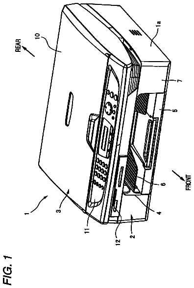
FIG. 1 is a perspective view of a multifunctional apparatus provided with an automatic document scanning apparatus according to an embodiment of the invention.
FIG. 2 is a plan view of the same.
FIG. 3 is a cross-sectional view of the automatic document scanning apparatus taken along the line III-III in FIG. 2.
FIG. 4 is an enlarged cross-sectional view of a principal portion of an automatic document transporting mechanism.
FIG. 5 is a cross-sectional view showing a state in which a lid cover member is opened.
FIG. 6 is a cross-sectional view showing a portion of a resilient supporting strip.
FIG. 7 is a cross-sectional view taken along the line VII-VII in FIG. 6.
FIG. 8 is an enlarged cross-sectional view showing a rotating member.
FIG. 9A is a plan view showing an arrangement of the rotating member according to another embodiment of the invention.
FIG. 9B is a plan view showing the arrangement of the rotating member according to yet another embodiment.
FIG. 10 is a plan view showing the arrangement of the rotating member according to a still another embodiment of the invention.
FIG. 11 is a schematic cross-sectional view of a paper-feeding cassette and a printer.
FIG. 12A is a plan view showing an arrangement of the rotating member according to still yet another embodiment of the invention.
FIG. 12B is a partially enlarged cross-sectional view of the rotating member according to still yet another embodiment of the invention.
Description of the preferred embodiments
Embodiments of the invention and their features and technical advantages may be understood by referring to FIGS. 1-12B, like numerals being used for like corresponding portions in the various drawings. Image scanning apparatus 2 in a multifunctional apparatus 1 may include a facsimile function, a scanner function, a copying function, and a printer function. When the image scanning apparatus 2 executes a copying function automatically for a plurality of documents, the image scanning apparatus 2 and an automatic document transporting mechanism 3 scan images of the plurality of documents as image data. Then, the copying function may be achieved by printing the images on printed media (papers P) by a transporting device and a printing device provided in a body case 4 on the basis of the scanned image data.
As shown in FIG. 1 and FIG. 2, arranged on a front portion of an upper surface of body case 4 of the multifunctional apparatus 1 may be an operation panel portion 5 having a numeric keypad for executing the facsimile function, the scanner function, and the copying function, button keys configured to issue commands of various operations, a liquid crystal panel configured to display contents of the commands or error messages. Hereinafter, a side where operation panel portion 5 of the body case 4, which may be formed of synthetic resin, may be located is referred to as "front" (near side) and with reference thereto, as "back" (inner, rear surface), "left", and "right" of the apparatus. Also, as described above, the fore-and-aft direction of the multifunctional apparatus 1 is referred to as X-direction, and the lateral direction is referred to as Y-direction.
As shown in FIG. 1, a paper-feeding cassette 7 configured to be inserted for feeding the printed media (papers P) may be arranged in an opening 4a on the front side of body case 4 of multifunctional apparatus 1. An upper side of opening 4a may function as a paper discharging port from which the printed papers P are discharged. Papers P, stacked on paper-feeding cassette 7, may be transported to a printer 60, where the images are printed, and printed papers P may be discharged on a paper discharge tray 71 arranged above the paper-feeding cassette 7. A user may obtain papers P discharged on paper discharge tray 71 from opening 4a.
Arranged on the rear side of operation panel portion 5 may be image scanning apparatus 2 configured to execute the scanner function and automatic document transporting mechanism 3 to be mounted thereon. As shown in FIG. 4 and FIG. 5, a glass panel 6 may be used as a transparent panel member for placing both a static document and a transported document on a case 2a of image scanning apparatus 2. A linear scanning device 8. e.g., a CIS (Contact Image Sensor), configured to scan image surfaces of the documents may be provided below the glass panel 6. Reciprocal linear scanning device 8, when placed on a linear guide shaft 9 along the Y-direction in FIG. 3, may be formed so as to be elongated in the X-direction in FIG. 1. Case 2a of the image scanning apparatus 2 may be mounted so as to be rotatable in the vertical direction about a pivot (not shown) provided horizontally in the body case 4 at the end on one side thereof
Automatic document transporting mechanism 3 (also referred to as an ADF), which transports the document automatically to the image scanning apparatus 2, may be provided on top of a pressing panel portion 10 which presses the static document placed on glass panel 6 with the image surface in abutment therewith. Pressing panel portion 10, which may be formed of synthetic resin, may be mounted on case 2a at a rear end thereof (the opposite side from operation panel portion 5) so as to be rotatable in the vertical direction via hinges 10a. A holding member (not shown), which may be formed of sponge, and a white panel may be bonded to a lower surface of pressing panel portion 10.
As shown in FIG. 4 and FIG. 5, exposure opening 36 may be at a position where scanning device 8 is kept stationary at a left end portion of the glass panel 6, which is an area on the left side from a guiding strip 11 elongated in the X-direction and bonded to an upper surface of glass panel 6. Documents D may be transported from exposure opening 36 in a first transporting direction with the image surface down are partly exposed therefrom, and the upper portion of a detecting position of the CIS corresponds to a scanning position Re of the transported document. A scanning area of the static document may be positioned on the right side from the guiding strip 11.
Automatic document transporting mechanism 3 according to an embodiment of the present invention may be arranged so as to be adjacent to a paper feeding tray portion 13 formed on an upper surface of an upper cover 12, which covers substantially entirely over the pressing panel portion 10, and paper discharge tray portions 14 arranged above the paper feeding tray portion 13. Automatic document transporting mechanism 3 may have a length shorter than the paper feeding tray portion 13 in terms of Y-direction, as shown in FIGS. 3-5. Automatic document transporting mechanism 3 may include a substantially U-shaped document transporting path having a first transporting portion configured to transport documents D to scanning position Re, as shown in FIGS. 5-6, positioned on one end portion of paper feeding tray portion 13 (one end portion in the Y-direction), a second transporting portion configured to reverse the transporting direction via scanning position Re, and a third transporting portion following the second transporting portion to transport the documents D in sequence to paper discharge tray portions 14.
In contrast, paper discharge tray portions 14 may be integrally provided on the upper side of a pair of document guides 13a projecting from the upper surface of upper cover 12. Then, when one of the document guides 13a is moved by hand, a pair of the document guides 13a may be moved in the X-direction simultaneously, so that the width can be adjusted according to the widthwise dimension of documents D in the X-direction by means of an interlocking mechanism 13b, as shown in FIG. 3, having a known structure including a rack lever and a pinion meshed therewith. Because paper discharge tray portions 14 are short in the Y-direction, a portion of paper feeding tray portion 13 near the other end portion thereof (the opposite side farthest from the side where the document transporting path is arranged), may also serve as a stacking portion where documents D discharged after scanning are stacked. In this manner, since an upstream portion of paper feeding tray portion 13, in terms of the first transporting direction, also serves as the stacking portion where documents D after scanning are stacked, the height of a portion for stacking documents D may be reduced, so that downsizing of the apparatus is effectively achieved.
A document stopper body 34 may be provided at the other end portion (rearmost portion) of upper cover 12 (paper feeding tray portion 13). Document stopper body 34 may be configured to come into abutment with leading edges of discharged documents D and prevent documents D from being further transported beyond document stopper body 34, that is, to prevent documents D from slipping down from the rearmost portion of paper feeding tray portion 13. In this case, by employing a storable configuration then a compact configuration may be achieved, such as a foldable configuration by forming a depressed portion 35 opened upward to allow document stopper body 34 to be fitted therein on the rearmost portion of the upper cover 12 and securing a proximal portion of document stopper body 34 in depressed portion 35 so as to be capable of rotating upstream, wherein document stopper body 34 is not protruded out from paper feeding tray portion 13 or the upper side when the multifunctional apparatus 1 is not in use or is packed. In short, document stopper body 34 may be movable between an upright state rotated (stood upright) from a depressed portion 35 to a position which allows the leading edges of documents D to come into abutment therewith and a stored state in depressed portion 35 to prevent the leading edge of documents D from coming into abutment therewith.
Automatic document transporting mechanism 3 may include a separating and transporting device having first rotating members, e.g., an intake roller 15 and a separation roller 16, and a first abutting member, e.g., an intake nip strip 17 and a separation pad 18, configured to separate one of the plurality of documents D placed on paper feeding tray portion 13 in a stacked state in sequence from the lowermost (positioned at the bottom) document D and transport the same to the first transporting portion (in the direction toward scanning position Re), one or both of these members being able to come into resilient abutment with the other one of those or with respect to each other. Automatic document transporting mechanism 3 further may include a reversely transporting device including a second rotating member, e.g., a large-diameter reverse roller 20, provided on the second transporting portion configured to reverse the document transported by the separating and transporting device from scanning position Re and transport further onward and second abutting members configured to be capable of coming into resilient abutment with the second rotating member. In addition, automatic document transporting mechanism 3 may include a cover member (lid cover member 19) capable of rotating about a rotating shaft provided at a position apart from the reversely transporting device and closer to paper discharge tray portions 14 than to paper feeding tray portion 13. Cover member may include second abutting members, e.g., a second pinch roller 22 and a third pinch roller 23, arranged therein and capable of opening at least part of the transporting path for the documents.
As shown in FIGS. 3-5, an intake roller 15 and a separation roller 16 and large-diameter reverse roller 20, which serve as the second rotating member, may be arranged on the upper surface of pressing panel portion 10 at a substantially center portion in the direction orthogonal to the transporting direction of documents D, i.e., a sheet transporting direction or a predetermined transporting direction. The centerline of rotation of a drive shaft 28, which supports reverse roller 20, may overlap an axial line of scanning position Re in a plan view, so that the lower end surface of the peripheral surface of reverse roller 20 opposes a surface to be scanned by scanning device 8.
Intake nip strip 17 and separation pad 18 may come into resilient abutment with the upper surfaces of intake roller 15 and separation roller 16, respectively. Second pinch roller 22 and third pinch roller 23 may be freely rotatable and capable of coming into resilient abutment with reverse roller 20. Intake nip strip 17, separation pad 18, second pinch roller 22, and third pinch roller 23, may be arranged on an inner surface of substantially L-shaped lid cover member 19.
Second pinch roller 22 and third pinch roller 23 may be pivotably supported at both ends of a spring strip 27, which may be formed of a metallic panel of a substantially L-shape in cross section, and a midsection of spring strip 27 is secured to the inner surface of lid cover member 19. A first pinch roller 21 serving as the driven roller may be arranged on the downstream side of the separation roller 16 in terms of the transporting direction. First pinch roller 21 may come into abutment with reverse roller 20 when mounted on a frame 24, which may be formed of metal and arranged on the upper surface of pressing panel portion 10 so as to be movable in the Y-direction. A rear end of a compression coil spring 25 acting as an urging (spring) device may be configured to resiliently press a rear end of frame 24 against the reverse roller 20, spring 25 is supported by a supporting strip 26.
Lid cover member 19 may be provided with a paper discharge auxiliary guide panel 29, elongated along the direction of the width of documents D, as a discharging shoot member for guiding the U-turned documents D to paper discharge tray portions 14 on the downstream side of the third pinch roller 23 in terms of the transporting direction and on the upstream side of paper discharge tray portions 14 in terms of the discharging direction. A front end portion 29a, which is on the upstream side in terms of the transporting direction of paper discharge auxiliary guide panel 29, may be formed to be inclined downward to a level lower than the upper surface of reverse roller 20, and a portion between a front end edge of paper discharge auxiliary guide panel 29 and an end edge 19b of an upper roof 19a of lid cover member 19 may correspond to a discharge port for discharged documents D. A horizontal portion 29b of the upper surface of paper discharge auxiliary guide panel 29 may be provided at substantially the same height as the upper surface paper discharge tray portions 14.
A proximal portion of an upper guide member 52 may be mounted to a portion of upper roof 19a of lid cover member 19 in the vicinity of end edge 19b via a pivot 53 so as to be rotatable in the vertical direction. Upper guide member 52 may be arranged substantially horizontally over at least part of the upper portion of paper discharge auxiliary guide panel 29 as the discharging shoot member, and as shown in FIG. 6, for example, over the substantially entire length from inclined front end portion 29a to horizontal portion 29b in regular use, i.e., a state in which reverse roller 20 is covered with lid cover member 19. In this configuration, since the upstream side of the documents D previously discharged and stacked on paper discharge auxiliary guide panel 29 may be regulated by a lower surface of upper guide member 52, and, thus, the stacked state substantially parallel to horizontal portion 29b is maintained. Accordingly, the leading edges of subsequent documents D may be easily and smoothly guided to the underside of previously discharged and stacked documents D. A large number of discharged documents D may be stacked in the same order as those having been placed on paper feeding tray portion 13.
The proximal portion of upper guide member 52 also may be mounted to a portion in the vicinity of end edge 19b so as to be rotatable in the vertical direction. In this case, a configuration in which a free end edge of upper guide member 52 comes into abutment with the upper surface of paper discharge tray portions 14 or paper feeding tray portion 13 to maintain lid cover member 19 in an opened state.
Intake nip strip 17 and separation pad 18 may be capable of rotating in the vertical direction about the proximal ends (upper end sides) on the side of a lower surface of paper discharge auxiliary guide panel 29, and intake nip strip 17 may be pressed against and urged against intake roller 15 via a compression coil spring 30 as a pressing device, and separation pad 18 may be pressed against and urged against the upper surface of separation roller 16 via a leaf spring 31 as the pressing device. Since the configuration may be adapted to suck documents D on paper feeding tray portion 13 in between intake nip strip 17 and intake roller 15, the lower surface side of paper discharge auxiliary guide panel 29 corresponds to an intaking shoot portion 32 for documents D fed from paper feeding tray portion 13.
Lid cover member 19 may be configured to be rotatable in the vertical direction about a rotating shaft (not shown) located on the side of the lower surface of paper discharge auxiliary guide panel 29 projecting from both sides in the vicinity of the proximal portion of intake nip strip 17, which corresponds to a position close to the separating and transporting device, i.e., the far side from the reverse roller 20. Therefore, as shown in FIGS. 3-4, when lid cover member 19 is closed, the intake nip strip 17 may be resiliently pressed against the upper surface of intake roller 15, separation pad 18 may be resiliently pressed against the upper surface of separation roller 16, and each of second pinch roller 22 and third pinch roller 23 are resiliently pressed against the peripheral surface of reverse roller 20 on the side of the reverse rotation.
As shown in FIG. 5, for example, when lid cover member 19 is rotated open and upward, the second pinch roller 22 and the third pinch roller 23 may move away from reverse roller 20. Also, in this state, when lid cover member 19 is rotated by about 120.degree., intake nip strip 17 and separation pad 18 may move away from intake roller 15 and separation roller 16, respectively, whereby document D pinched at an abutment or nip portion between them can be removed easily, so that a paper jam may be resolved. Document D pinched at the abutment portion between first pinch roller 21 and reverse roller 20, which can be moved against an urging force of the coil spring 25 as the pressing device, may be pulled out irrespective of the urging force.
Documents D to be scanned may be stacked with the image surfaces down between lower surface of panel-shaped paper discharge tray portions 14 and paper feeding tray portion 13. By forming the paper discharge tray portions 14 so as to incline in such a manner that the height from the upper surface of paper feeding tray portion 13 to the horizontal lower surface of paper discharge tray portions 14 becomes lower at a distal end side 14a closer to intake roller 15, guiding operation of documents D stacked on paper feeding tray portion 13 in between intake roller 15 and intake nip strip 17 may be smoothly achieved. Also, by providing an intake device including intake roller 15 and intake nip strip 17, documents D stacked on horizontal paper feeding tray portion 13 may be reliably delivered to a position of a separating device including separation roller 16 and separation pad 18. In order to ensure this operation, the diameters and the peripheral speeds of intake roller 15 and separation roller 16 may be set to be the same.
As shown in FIG. 4, arranged on both left and right outer sides, in the width direction of documents D, with the intermediary of reverse roller 20 on the lower side may be pressing members 40 configured to press the image surface of document D against the surface of glass panel 6 without gap at the exposure opening including scanning position Re. Pressing members 40 may be molded, by injection molding of synthetic resin, integrally with flat panel shaped large pressing panel portion 10. In this case, the proximal portions, i.e., portions close to the end edges in the width direction of documents D, of the pressing members 40 may be integrally connected to portions in the vicinity of shaft supporting portions (not shown) of drive shaft 28 provided on the side portions of pressing panel portion 10. Referring to FIGS. 1-2, provided on the outside of the one of the shaft supporting portions may be a transmitting portion case 45 which allows storage of the drive shaft 28, a transmission gear mechanism for transmitting a rotational drive force to intake roller 15 and separation roller 16, respectively, and a drive motor.
Referring to FIG. 4 and FIG. 7, pressing members 40 may be formed into a substantially semi-arcuate shell shape projecting downward, and may be integrally formed with resilient hook members 41 directed upward on the side closer to the both right and left sides of the reverse roller 20. Resilient hook members 41 may be fitted to each end of drive shaft 28 and are hung therefrom. Accordingly, the heightwise position of the lower surface of pressing members 40 with respect to glass panel 6 may be secured with a simple configuration.
Also, by bonding a white tape or by applying white coating material on the lower surface of pressing members 40, in an area including scanning position Re, detection of reference chromaticity and luminance in scanning device 8 may be achieved.
A discharge guiding device may guide subsequent document D in between paper discharge tray portions 14 and the previously discharged documents D stacked in the same order. When document D, after having been scanned, may make a U-turn and be discharged to paper discharge auxiliary guide panel 29 and then paper discharge tray portions 14 on the upper side of reverse roller 20, that is, with the image surfaces of the respective documents D facing up in the third transporting portion and other documents D are already discharged are present on paper discharge tray portions 14. The discharge guiding device, which may be provided in the third transporting portion on the upstream side of the paper discharge tray portions 14 in terms of the document discharging direction, may guide the subsequent document D in between the upper surface of paper discharge tray portion 14 and previously discharged document D.
According to the discharge guiding device in one exemplary embodiment of the invention shown in FIG. 4, in the state in which lid cover member 19 is closed, the heightwise position of the abutment portion between third pinch roller 23 and the upper side of the peripheral surface of reverse roller 20 is higher than front end portion 29a, and is lower than the heightwise position of the upper surface of horizontal portion 29b of the paper discharge auxiliary guide panel 29.
As shown in FIG. 4 and FIG. 7, a pair of fitted members 46 may be arranged on the upper side of the both left and right outer sides in the intermediary of reverse roller 20. Fitted members 46 may be formed substantially into a half cylinder shape, when viewed in cross section, extending in the width direction of documents D. Fitted members 46 may be provided so as to continue from upper ends of pressing members 40, and, thus, cover the drive shaft 28 from above, and fitted members 46 and pressing members 40 may be connected by engaging devices (not shown). Guide members 47 may be formed integrally with an outer peripheral surface of fitted members 46 so as to extend obliquely upward from the position corresponding to the abutment position between third pinch roller 23 and reverse roller 20 toward the downstream side in terms of the transporting direction and being in proximity to front end portion 29a of the paper discharge auxiliary guide panel 29. Uppermost end portions 47a of respective guide members 47 may be positioned higher than the abutment position between third pinch roller 23 and reverse roller 20. In this configuration, document D released from the abutment position between third pinch roller 23 and reverse roller 20 may be guided upward along inclined guide members 47 to uppermost end portions 47a. However, when uppermost end portions 47a are positioned at a lower level than the horizontal portion 29b, subsequent document D may be guided and transported in such a manner that the leading edge thereof approaches to the underside of the lowermost document D from among the previously discharged documents D and slips over the paper discharge auxiliary guide panel 29, whereby discharged documents D may be stacked in the same order as those having been placed on paper feeding tray portion 13.
As shown in FIGS. 6-7, in addition to, or instead of guide members 47, resilient supporting strips 49 may be provided for lifting document D from the abutment position between the third pinch roller 23 and the reverse roller 20. Resilient supporting strips 49 may be formed of resilient panel members of elastic synthetic resin, such as PET (polyethylene terephthalate), having a thickness of approximately 0.2 mm to 1 mm, and are bent substantially into an L-shape. Proximal portions of resilient supporting strips 49 may be fixed with an adhesive agent or the like to depressed portions 46a formed at suitable positions of the outer peripheral surface of fitted members 46 in terms of the width direction of documents D and at the heightwise position in the vicinity of that of the abutment position between third pinch roller 23 and reverse roller 20. Resilient supporting strips 49 may be arranged so as to incline upward toward the downstream side in terms of the transporting direction to an uppermost edge 49a at a heightwise position higher than horizontal portion 29b, and a free end portion 49b bent downward and extended from uppermost edge 49a is inserted into a groove hole or slit 50 formed on fitted members 46. In this configuration, document D may be released from the abutment position between third pinch roller 23 and reverse roller 20 rides on resilient supporting strips 49, which are bent slightly downward by the weight of document D. Free end portion of the document D lifted by a resilient force of the resilient supporting strips 49 by itself in this state may be discharged toward the upper surface of paper discharge auxiliary guide panel 29. Therefore, the leading edge of the subsequent document D, approaching the underside of previously discharged documents D, may be guided and transported onto the paper discharge auxiliary guide panel 29, so that discharged documents D are stacked in the same order as documents D stacked on paper feeding tray portion 13. Therefore, the operator does not have to change the stacking order of documents D later.
When inclined free end portions 49b extending downward of L-shaped resilient supporting strips 49 are inserted into the slit holes 50 formed on the fitted members 46, the positions of free end portions 49b may be moved in the vertical direction along slit holes 50 when the document D is placed thereon and resilient supporting strips 49 are bent downward due to its resiliency, the direction of deformation of the resilient supporting strips 49 may be regulated, and, thus, the action of the leading edge of subsequent document D approaching the lower surface of the previously discharged document D may be further ensured.
Referring to FIG. 7, lid cover member 19 may be formed integrally with elongated ribs 19c extending along the Y-direction to end edge 19b at a suitable pitch in the X-direction on the inner surface of lid cover member 19. By arranging resilient supporting strips 49 between the plurality of ribs 19c formed at the suitable positions, the range of vertical movement of the uppermost edge 49a may be increased, so that the action of the resilient supporting strips 49 to lift discharged document D may be further ensured.
The description continues in the full USPTO document.
 Lapsed, fee not paid5 drawings