Background of the invention
1. Field of the invention
The present invention relates to a honeycomb structure and, more specifically, to a honeycomb structure functioning not only as a catalyst carrier but also as a heater.
2. Description of related art
There has conventionally been used a cordierite honeycomb structure having a catalyst loaded thereon for treating harmful substances in exhaust gas discharged from an automobile engine. In addition, there is known the use of a honeycomb structure formed of a silicon carbide sintered body for purification of exhaust gas (see, e.g., Patent Document 1).
In the case of treating exhaust gas by a catalyst loaded on a honeycomb structure, it is necessary to raise the temperature of the catalyst up to predetermined temperature. However, since the catalyst has low temperature at the time of engine start-up, there is a problem of insufficient purification of exhaust gas.
Therefore, there is investigated a method of raising temperature of exhaust gas by setting a metal heater on the upstream side of the honeycomb structure having a catalyst loaded thereon (see, e.g., Patent Document 2).
Prior art document
Patent Document
Patent Document 1: Japanese Patent No. 4136319 Patent Document 2: Japanese Patent No. 2931362
When the heater as described above is mounted on an automobile and used, the power source used for the electrical system of the automobile is shared, and a power source having a high voltage of, for example, 600V is used. However, since a metal heater has a low electric resistance, there is a problem of damaging a power source circuit due to extreme flow of an electric current in the case of using a power source having a high voltage of 600V.
In addition, when the heater is made of metal, since it is difficult to load a catalyst even if the heater is machined to have a honeycomb structure, it is difficult to unitarily join the heater and the catalyst.
Therefore, there has been desired a porous carrier where a catalyst can easily be loaded and which can electrically generate heat. In order to function as a carrier for an exhaust gas purification catalyst, a carrier having a partition wall thickness of 300 .mu.m and a cell density of 45 cells/cm.sup.2 like a DPF is insufficient, and a catalyst having thinner partition walls and a higher cell density is required.
The present invention has been made in view of the aforementioned problems and aims to provide a honeycomb structure having an electrode portion which can easily be formed and functioning not only as a catalyst carrier, but also as a heater.
Summary of the invention
In order to solve the aforementioned problems, according to the present invention, there is provided the following honeycomb structure.
[1] A honeycomb structure comprising:
a cylindrical honeycomb structural section having porous partition walls separating and forming a plurality of cells functioning as fluid passages and extending over from one end face to the other end face and an outer peripheral wall located in the outermost periphery, a pair of lateral electrodes disposed on a side face of the honeycomb structural section, and at least one intermediate layer between the honeycomb structural section and the lateral electrodes; wherein the honeycomb structural section contains silicon carbide particles as a framework material and silicon as a bonding material for bonding the silicon carbide particles together, the silicon carbide particles as the framework material for the honeycomb structural section has an average particle diameter of 3 to 40 .mu.m, and the ratio (Si/SiC) of silicon (Si) to silicon carbide (SiC) is 10/90 to 40/60, the lateral electrodes have an average particle diameter of the silicon carbide particles of 10 to 70 .mu.m, and the ratio (Si/SiC) of silicon (Si) to silicon carbide (SiC) is 20/80 to 50/50, the intermediate layer has an average particle diameter of the silicon carbide particles between that of the honeycomb structural section and that of the lateral electrodes and a ratio of silicon (Si) to silicon carbide (SiC) between that of the honeycomb structural section and that of the lateral electrodes, and an electric resistance between the lateral electrodes is 2 to 100.OMEGA..
[2] The honeycomb structure according to [1], wherein the honeycomb structural section has a porosity of 30 to 60%, an average pore size of 2 to 20 .mu.m, a partition wall thickness of 50 to 200 .mu.m, and a cell density of 50 to 150 cells/cm.sup.2.
[3] The honeycomb structure according to [1] or [2], wherein the lateral electrode and/or the intermediate layer contain(s) at least one of aluminum, molybdenum, tin, and zirconium.
[4] The honeycomb structure according to any one of [1] to [3], wherein a surface layer having the same composition as the intermediate layer is provided on a surface of the lateral electrode.
By providing an intermediate layer, adhesion between the honeycomb structural section (substrate) and the electrode portion increases to inhibit exfoliation upon production, and the electric resistance of the interface between the honeycomb structural section and the electrode portion decreases to be able to suppress heat generation right under the electrode portion. By adding aluminum, molybdenum, tin, or zirconium to silicon (Si), the electric resistance of the electrode portion can be reduced. In addition, in the case of performing the second firing after disposing the electrode after firing the substrate, the firing temperature for the second firing can be lowered.
Brief description of the drawings
FIG. 1 is a perspective view schematically showing one embodiment of a honeycomb structure of the present invention.
FIG. 2 is a perspective view showing a cross section parallel to the cell extension direction of an embodiment of a honeycomb structure of the present invention.
FIG. 3 is a schematic view schematically showing a cross section of a honeycomb structural section, an intermediate layer, and an electrode portion of a honeycomb structure of the present invention.
FIG. 4A is a schematic view showing a state where an electrode portion is disposed on an intermediate layer in a cross section perpendicular to the cell extension direction of an embodiment of a honeycomb structure of the present invention.
FIG. 4B is a schematic view showing a state where an electrode portion is disposed in an intermediate layer in a cross section perpendicular to the cell extension direction of another embodiment of a honeycomb structure of the present invention.
FIG. 5 is a lateral view schematically showing another embodiment of a honeycomb structure of the present invention.
FIG. 6 is a schematic view showing the A-A' cross section of FIG. 5.
FIG. 7 is a schematic view showing a lateral electrode provided with a surface layer which is the same as the intermediate layer on the surface.
FIG. 8 is a perspective view schematically showing another embodiment of a honeycomb structure of the present invention.
Detailed description of the invention
Hereinbelow, embodiments of the present invention will be described with referring to drawings. The present invention is by no means limited to the following embodiments, and changes, modifications, and improvements may be added as long as they do not deviate from the scope of the invention.
Honeycomb Structure:
As shown in FIGS. 1 to 3 and 6, an embodiment of a honeycomb structure of the present invention is provided with a cylindrical honeycomb structural section (substrate) 4 having porous partition walls 1 separating and forming a plurality of cells 2 functioning as fluid passages and extending over from one end face 11 to the other end face 12 and an outer peripheral wall 3 located in the outermost periphery (disposed so as to surround the outer periphery of the entire partition walls 1), a pair of lateral electrodes 23, 23 disposed on a side face of the honeycomb structural section 4, and at least one intermediate layer 15 between the honeycomb structural section 4 and the lateral electrodes 23. The honeycomb structural section 4 contains silicon carbide particles (silicon carbide) as a framework material and silicon as a bonding material for bonding the silicon carbide particles together. The silicon carbide particles as the framework material have an average particle diameter of 3 to 40 .mu.m, and the ratio (Si/SiC) of silicon (Si) to silicon carbide (SiC) is 10/90 to 40/60. The lateral electrodes 23 have an average particle diameter of the silicon carbide particles of 10 to 70 .mu.m, and the ratio (Si/SiC) of silicon (Si) to silicon carbide (SiC) is 20/80 to 50/50. The intermediate layer 15 has an average particle diameter of the silicon carbide particles between that of the honeycomb structural section 4 and that of the lateral electrodes 23 and a ratio of silicon (Si) to silicon carbide (SiC) between that of the honeycomb structural section 4 and that of the lateral electrodes 23. An electric resistance between the lateral electrodes 23 and 23 is 2 to 100.OMEGA..
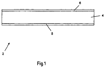
FIG. 1 is a perspective view schematically showing an embodiment of a honeycomb structure 100 of the present invention. FIG. 2 is a schematic view showing a cross section parallel to the cell extension direction of an embodiment of the honeycomb structure 100 of the present invention. Incidentally, FIG. 2 does not show any lateral electrode 23. FIG. 3 is a schematic view schematically showing a cross section of an electrode portion 21 of a honeycomb structural section 4, an intermediate layer 15, and a lateral electrode 23.
Thus, in the honeycomb structure 100 of the present embodiment, since the electric resistance between the lateral electrodes 23 and 23 is 2 to 100.OMEGA., an electric current does not flow excessively even if en electric current is allowed to flow by the use of a power source having a high voltage, and therefore it can suitably be used as a heater.
In the honeycomb structure 100 of the present embodiment, the partition walls 1 and the outer peripheral wall 3 contains silicon carbide particles as a framework material and silicon as a bonding material for bonding the silicon carbide particles together. In the honeycomb structure 100 of the present embodiment, a plurality of silicon carbide particles are bonded together by silicon so as to form pores among the silicon carbide particles.
The honeycomb structure 100 of the present embodiment is provided with a pair of lateral electrodes 23 disposed on a side face of the honeycomb structural section 4. The lateral electrode 23 is constituted of an electrode portion 21 and an electrode terminal protrusion 22 (There is a case that the lateral electrode 23 has only the electrode portion 21 without the electrode terminal protrusion 22). The honeycomb structure 100 of the present embodiment generates heat by applying a voltage between the pair of electrode portions 21 and 21. The voltage to be applied is preferably 50 to 800V, more preferably 500 to 700V. For example, in the case of using a power source having a voltage of 600V for an automobile electrical system, it is preferable to apply the voltage of 600V.
The honeycomb structure 100 of the present embodiment has a partition wall thickness of 50 to 200 .mu.m, preferably 70 to 130 .mu.m. The partition wall thickness within such a range enables to suppress excessive increase of pressure loss upon allowing exhaust gas to flow even if a catalyst is loaded while using the honeycomb structure 100 as a catalyst carrier. When the partition wall thickness is smaller than 50 .mu.m, it is not preferable because the strength of the honeycomb structure is low. When the partition wall thickness is larger than 200 .mu.m, it is not preferable because of the large pressure loss upon allowing exhaust gas to flow in the case of loading a catalyst while using the honeycomb structure 100 as a catalyst carrier.
The honeycomb structure 100 of the present embodiment has a cell density of 50 to 150 cells/cm.sup.2, preferably 70 to 100 cells/cm.sup.2. The cell density within such a range enables to improve purification performance of the catalyst in a state where the pressure loss upon allowing exhaust gas to flow is made small. The cell density below 50 cells/cm.sup.2 is not preferable because the catalyst load area is small. The cell density above 150 cells/cm.sup.2 is not preferable because the pressure loss upon allowing exhaust gas to flow is large in the case of loading a catalyst while using the honeycomb structure 100 as the catalyst carrier.
In the honeycomb structure 100 of the present embodiment, the average particle diameter of the silicon carbide particles (framework material) constituting the honeycomb structural section 4 is 3 to 40 .mu.m, preferable 10 to 35 .mu.m. The average particle diameter of the silicon carbide particles constituting the honeycomb structural section 4 in such a range enables the volume electric resistance at 400.degree. C. of a material for a honeycomb structure 100 to be 5 to 200 .OMEGA.cm. When the average particle diameter of the silicon carbide particles is below 3 .mu.m, the volume electric resistance at 400.degree. C. of the honeycomb structure 100 becomes large, which is not preferable. When the average particle diameter of the silicon carbide particles is above 40 .mu.m, the volume electric resistance at 400.degree. C. of the honeycomb structure 100 becomes small, which is not preferable. In addition, when the average particle diameter of the silicon carbide particles is above 40 .mu.m, upon extrusion of a honeycomb formed body, a die for extrusion may be clogged with the forming raw material, which is not preferable. The average particle diameter of the silicon carbide particles is a value measured by a laser diffraction method.
The ratio (Si/SiC) of silicon (Si) to silicon carbide (SiC) constituting the honeycomb structural section 4 is preferably 10/90 to 40/60. It is more preferably 15/85 to 35/65. The ratio of silicon to silicon carbide particles contained in the honeycomb structural section 4 within such a range enables to obtain an appropriate volume electric resistance.
In the honeycomb structure 100 of the present embodiment, the volume electric resistance at 400.degree. C. of a material for the honeycomb structural section 4 is 1 to 40 .OMEGA.cm, preferably 10 to 35 .OMEGA.cm. When the volume electric resistance at 400.degree. C. is below 1 .OMEGA.cm, it is not preferable because the electric current flows excessively when the honeycomb structure 100 is electrified by a power source of 600V (the voltage is not limited to 600V). When the volume electric resistance at 400.degree. C. is above 40 .OMEGA.cm, it is not preferable because the electric current hardly flows to sometimes cause insufficient heat generation when the honeycomb structure 100 is electrified by a power source of 600V (the voltage is not limited to 600V). The volume electric resistance at 400.degree. C. of the honeycomb structure is a value measured by a four-terminal method.
In the honeycomb structure 100 of the present embodiment, the electric resistance (electric resistance between the lateral electrodes 23 and 23) at 400.degree. C. of the honeycomb structure 100 is preferably 1 to 30.OMEGA., furthermore preferably 10 to 25.OMEGA.. When the electric resistance at 400.degree. C. is smaller than 1.OMEGA., it is not preferable because the electric current flows excessively when the honeycomb structure 100 is electrified by a power source of, for example, 600V (the voltage is not limited to 600V). When an electric resistance at 400.degree. C. is larger than 30.OMEGA., it is not preferable because the electric current hardly flows when the honeycomb structure 100 is electrified by a power source of, for example, 600V (the voltage is not limited to 600V). The electric resistance at 400.degree. C. of the honeycomb structure is a value measured by a four-terminal method.
In the honeycomb structure 100 of the present embodiment, the volume electric resistance at 400.degree. C. of the electrode portion 21 is lower than the volume electric resistance at 400.degree. C. of the honeycomb structural section 4, the volume electric resistance at 400.degree. C. of the electrode portion 21 is 40% or less of the volume electric resistance at 400.degree. C. of the honeycomb structural section 4, and it is preferably 25 to 35%. By specifying the volume electric resistance at 400.degree. C. of electrode portion 21 to 40% or less of the volume electric resistance at 400.degree. C. of the honeycomb structural section 4, the electrode portion 21 more effectively functions as an electrode.
The porosity of the partition walls 1 of the honeycomb structural section 4 is preferably 30 to 60%, more preferably 35 to 45%. The porosity of below 30% is not preferable because deformation upon firing becomes large. The porosity of above 60% is not preferable because the strength of the honeycomb structure becomes low. The porosity is a value measured with a mercury porosimeter.
The average pore size of the partition walls 1 of the honeycomb structural section 4 is preferably 2 to 20 .mu.m, more preferably 10 to 20 .mu.m. When the average pore size is smaller than 2 .mu.m, the volume electric resistance becomes too large, which is not preferable. When the average pore size is larger than 20 .mu.m, the volume electric resistance becomes too small, which is not preferable. The average pore size is measured by a mercury porosimeter.
In the honeycomb structure 100 of the present embodiment, the partition walls 1 and the outer peripheral wall 3 preferably contain silicon carbide particles as a framework material and silicon as a bonding material for bonding the silicon carbide particles together as the main components and may be formed of only silicon carbide and silicon. Even in the case that the partition walls 1 and the outer peripheral wall 3 are formed of only silicon carbide and silicon, a slight amount of 10 mass % or less of impurities may be contained. In the case that the partition walls 1 and the outer peripheral wall 3 contain substances (a slight amount of impurities) besides "silicon carbide and silicon", silicon oxide and the like can be mentioned as other substances contained in the partition walls 1 and the outer peripheral wall 3. Here, "the partition walls 1 and the outer peripheral wall 3 contain silicon carbide particles and silicon as the main components" means that the partition walls 1 and the outer peripheral wall 3 contain silicon carbide particles and silicon at 90 mass % or more of the entire components.
As shown in FIG. 1, it is preferable that each of a pair of intermediate layers 15, 15 extends in the cell 2 extension direction of the honeycomb structural section 4 and is formed into a "strip shape" extensively between both the end portions (between both the end faces 11 and 12). In a cross section perpendicular to the cell 2 extension direction, it is preferable that one intermediate layer 15 of the pair of intermediate layers 15, 15 is disposed on the opposite side across the central portion O of the honeycomb structural section 4 from the other intermediate layer 15. Since the intermediate layer 15 is formed into a strip shape extensively between both the end portions (between both the end faces 11, 12) of a honeycomb structural section 4 in such a manner that the longitudinal direction of the strip-shaped intermediate layer 15 extends in the cell 2 extension direction of the honeycomb structural section 4, the entire honeycomb structural section 4 can be heated more uniformly by forming a lateral electrode 23 on the intermediate layer 15. In addition, by disposing one intermediate layer 15 of the pair of intermediate layers 15, 15 on the opposite side across the central portion O of the honeycomb structural section 4 from the other intermediate layer 15 in a cross section perpendicular to the cell 2 extension direction, the entire honeycomb structural section 4 can be heated more uniformly.
The length (width) of the intermediate layer 15 in the "peripheral direction R of the honeycomb structural section 4" is preferably 1/30 to 1/3, more preferably 1/10 to 1/4, of the length in the peripheral direction R (outer peripheral length) of the side face 5 of the honeycomb structural section 4. Such a range enables to heat the entire honeycomb structural section 4 more uniformly. When the length (width) of the intermediate layer 15 in the peripheral direction R of the honeycomb structural section 4 is smaller than 1/30 of the length in the peripheral direction R of the side face 5 of the honeycomb structural section 4, it may become impossible to uniformly generate heat. When it is larger than 1/3, heating of the vicinity of the central portion of the honeycomb structural section 4 may become difficult.
The thickness of the intermediate layer 15 is preferably 0.05 to 2.0 mm, more preferably 0.1 to 0.5 mm. Such a range enables to generate heat uniformly. When the thickness of the intermediate layer 15 is smaller than 0.05 mm, bonding becomes insufficient to have high interface electric resistance, which may make uniform heat generation impossible. When it is larger than 2.0 mm, breakage may be caused upon canning.
As shown in FIGS. 4A and 4B, it is preferable that the intermediate layer 15 is disposed on the surface of the outer peripheral wall 3. FIGS. 4A and 4B are schematic views showing a state where the intermediate layer 15 is disposed on the outer peripheral wall 3 in a cross section perpendicular to the cell extension direction of an embodiment of a honeycomb structure.
It is preferable that the intermediate layer 15 contains silicon carbide particles and silicon as the main components. Here, "contains silicon carbide particles and silicon as the main components" means that the total mass of silicon carbide particles and silicon is 90 mass % or more of the mass of the entire intermediate layer. Since the components of the intermediate layer 15 and the components of the honeycomb structural section 4 become the same (or close) by the intermediate layer 15 containing silicon carbide particles and silicon as the main components, the thermal expansion coefficient of the intermediate layer 15 becomes the same as (or close to) that of the honeycomb structural section 4. In addition, since the material is the same (or close), the bonding strength between the intermediate layer 15 and the honeycomb structural section 4 becomes high. Therefore, even if thermal stress is applied to the honeycomb structure, peeling of the intermediate layer 15 from the honeycomb structural section 4 and breakage of the bonding portion between the intermediate layer 15 and the honeycomb structural section 4 can be inhibited.
In the case that the main components of the intermediate layer 15 are silicon carbide particles and silicon, the average particle diameter of the silicon carbide particles contained in the intermediate layer 15 is between that of the honeycomb structural section and that of the lateral electrode. Specifically, 3 to 70 .mu.m is preferable, and 15 to 50 .mu.m is more preferable. The average particle diameter of the silicon carbide particles contained in the intermediate layer 15 within such a range enables to lower the electric resistance at the interface between the honeycomb structural section 4 and the lateral electrode 23. When the average pore size of the silicon carbide particles contained in the intermediate layer 15 is smaller than 3 .mu.m, the volume electric resistance at 400.degree. C. of the intermediate layer 15 may become too large. When the average pore size of the silicon carbide particles contained in the intermediate layer 15 is larger than 70 .mu.m, the strength of the intermediate layer 15 is low, and breakage may be caused. The average particle diameter of the silicon carbide particles contained in the intermediate layer 15 is a value measured by a laser diffraction method.
The ratio of silicon (Si) to silicon carbide (SiC) contained in the intermediate layer 15 is between that of the honeycomb structural section 4 and that of the lateral electrode 23. Specifically, the ratio (Si/SiC) of silicon (Si) to silicon carbide (SiC) is preferably 10/90 to 50/50, more preferably 30/70 to 40/60. The ratio of silicon to silicon carbide particles contained in the intermediate layer 15 within such a range enables to obtain an appropriate volume electric resistance. When the ratio of silicon to silicon carbide particles contained in the intermediate layer 15 is smaller than 10/90, the volume electric resistance may become too large. When it is larger than 50/50, deformation may be caused easily upon production.
As shown in FIG. 1, it is preferable that each of the pair of electrode portions 21, 21 extends in the cell 2 extension direction of the honeycomb structural section 4 and is formed into a "strip shape" extensively between both the end portions (between both the end faces 11 and 12). In addition, it is preferable that one electrode portion 21 of the pair of electrode portions 21, 21 is disposed on the opposite side across the central portion O of the honeycomb structural section 4 from the other electrode portion 21 in a cross section perpendicular to the cell 2 extension direction. Since the electrode portion 21 is formed into a strip shape extensively between both the end portions (between both the end faces 11 and 12) of the honeycomb structural section 4 so that the longitudinal direction of the strip-shaped electrode portion 21 may extend in the cell 2 extension direction of the honeycomb structural section 4 in such a manner, the entire honeycomb structural section 4 can be heated more uniformly. In addition, since one electrode portion 21 of the pair of electrode portions 21, 21 is disposed on the opposite side across the central portion O of the honeycomb structural section 4 from the other electrode portion 21 in a cross section perpendicular to the cell 2 extension direction, the entire honeycomb structural section 4 can be heated more uniformly.
As shown in FIG. 1, the electrode portions 21 may be disposed on the honeycomb structural section 4 so as to extend over between both the end portions (between both the end faces 11 and 12) of the honeycomb structural section 4. However, as shown in FIG. 8, there may have a gap between the end portions 21a, 21b "in the cell 2 extension direction" of the electrode portion 21 and the end portions (one end face 11, the other end face 12) of the honeycomb structural section 4. In the case of having a gap between the end portions 21a, 21b "in the cell 2 extension direction" of the electrode portion 21 and the end portions (one end face 11, the other end face 12) of the honeycomb structural section 4, the length "in the cell 2 extension direction" of the electrode portion 21 is preferably 50% or more, more preferably 80% or more, particularly preferably 90% or more, of the length "in the cell extension direction" of the honeycomb structure. FIG. 8 is a perspective view schematically showing another embodiment (honeycomb structure 300) of a honeycomb structure of the present invention.
The length (width) of the electrode portion 21 in the "peripheral direction R of the honeycomb structural section 4" is preferably 1/30 to 1/3, more preferably 1/10 to 1/4, of the length in the peripheral direction R (outer peripheral length) of the side face 5 of the honeycomb structural section 4. Such a range enables to heat the entire honeycomb structural section 4 more uniformly. When the length (width) of the electrode portion 21 in the peripheral direction R of the honeycomb structural section 4 is smaller than 1/30 of the length in the peripheral direction R of the side face 5 of the honeycomb structural section 4, heat may not be generated uniformly. When it is larger than 1/3, heating of the vicinity of the central portion of the honeycomb structural section 4 may be difficult.
The thickness of the electrode portion 21 is preferably 0.05 to 2.0 mm. Such a range enables to generate heat uniformly. When the thickness of the electrode portion 21 is smaller than 0.05 mm, the electric resistance becomes high, which may make uniform heat generation impossible. When it is larger than 2.0 mm, breakage may be caused upon canning.
As shown in FIG. 4A, it is preferable that the electrode portion 21 is disposed on the surface of the intermediate layer 15. In addition, as shown in FIG. 4B, also the electrode portion 21 in a state where a part (the side in contact with the intermediate layer 15) of the electrode portion 21 is embedded in the intermediate layer 15 while the other part (a part on the surface side) is exposed to the outside (on the surface side) from the intermediate layer 15 is a preferable mode. FIG. 4A is a schematic view showing a state where the electrode portion 21 is disposed on the intermediate layer 15 in a cross section perpendicular to the cell extension direction of an embodiment of a honeycomb structure of the present invention. FIG. 4B is a schematic view showing a state where the electrode portion 21 is disposed in the intermediate layer 15 in a cross section perpendicular to the cell extension direction of another embodiment of a honeycomb structure of the present invention. Incidentally, in FIGS. 4A to 4B, only a part of the outer peripheral wall 3, the intermediate layer 15, and one electrode portion 21 are shown, and partition walls and the like are not shown.
It is preferable that the electrode portion 21 contains silicon carbide particles and silicon as the main components. Here, the phase "silicon carbide particles and silicon as the main components" means that the total mass of silicon carbide particles and silicon is 90 mass % or more of the mass of the entire intermediate layer. Since the components of the electrode portion 21 and the components of the honeycomb structural section 4 become the same (or close) by the electrode portion 21 containing silicon carbide particles and silicon as the main components, the thermal expansion coefficient of the electrode portion 21 becomes the same as (or close to) that of the honeycomb structural section 4. In addition, since the material is the same (or close), the bonding strength between the detection portion 21 and the honeycomb structural section 4 becomes high. Therefore, even if thermal stress is applied on the honeycomb structure, peeling of the electrode portion 21 from the honeycomb structural section 4 and breakage of the bonding portion between the electrode portion 21 and the honeycomb structural section 4 can be inhibited.
The volume electric resistance at 400.degree. C. of electrode portion 21 is preferably 0.1 to 10 .OMEGA.cm, more preferably 1 to 10 .OMEGA.cm. The volume electric resistance at 400.degree. C. of electrode portion 21 within such a range enables the pair of electrode portions 21, 21 to effectively play a role of electrodes in the pipe where high-temperature exhaust gas flows. When the volume electric resistance at 400.degree. C. of electrode portion 21 is smaller than 0.1 .OMEGA.cm, deformation may be caused upon production. When the volume electric resistance at 400.degree. C. of electrode portion 21 is larger than 10 .OMEGA.cm, the flow of the electric current becomes hard, and therefore, it may become difficult for the electrode portion 21 to play a role as the electrode.
The electrode portion 21 has a porosity of preferably 30 to 60%, more preferably 45 to 55%. The electrode portion 21 having a porosity within such a range enables to obtain a preferable volume electric resistance. When the porosity of the electrode portion 21 is below 30%, deformation may be caused upon production. When the porosity of the electrode portion 21 is above 60%, the volume electric resistance may become too high. The porosity is a value measured with a mercury porosimeter.
The electrode portion 21 has an average pore size of preferably 5 to 45 .mu.m, more preferably 20 to 40 .mu.m. By the electrode portion 21 having an average pore size in such a range, an appropriate volume electric resistance can be obtained. When the average pore size of the electrode portion 21 is smaller than 5 .mu.m, the volume electric resistance may become too high. When the average pore size of the electrode portion 21 is larger than 45 .mu.m, the strength become low, and breakage may be caused. The average pore size is a value measured by a mercury porosimeter.
In the case that the main components of the electrode portion 21 are silicon carbide particles and silicon, the silicon carbide particles contained in electrode portion 21 has an average particle diameter of preferably 10 to 70 .mu.m, more preferably 40 to 60 .mu.m. By the silicon carbide particles contained in the electrode portion 21 being within such a range, the volume electric resistance at 400.degree. C. of the electrode portion 21 can be controlled to 0.1 to 2.0 .OMEGA.cm. When the average pore size of the silicon carbide particles contained in the electrode portion 21 is smaller than 10 .mu.m, the volume electric resistance at 400.degree. C. of the electrode portion 21 may become too large. When the average pore size of the silicon carbide particles contained in the electrode portion 21 is larger than 70 .mu.m, the strength of the electrode portion 21 becomes low, and breakage may be caused. The average particle diameter of the silicon carbide particles contained in the electrode portion 21 is a value measured by a laser diffraction method.
The ratio (Si/SiC) of silicon (Si) to silicon carbide (SiC) contained in the electrode portion 21 is 20/80 to 50/50, more preferably 20/80 to 40/60. The ratio of silicon to silicon carbide particles contained in the electrode portion 21 within such a range enables to obtain an appropriate volume electric resistance. When the ratio of silicon to silicon carbide particles contained in the electrode portion 21 is smaller than 20/80, the volume electric resistance may become too large. When it is larger than 50/50, deformation may easily be caused upon production.
In the honeycomb structure of the present embodiment, it is preferable that, when a tangent line in contact with the outer periphery of the honeycomb structural section is drawn in the central portion of the electrode portion in the peripheral direction of the honeycomb structural section in a cross section perpendicular to the cell extension direction, the tangent line is parallel to any of the partition walls. This inhibits breakage upon canning.
The thickness of the outer peripheral wall 3 constituting the outermost periphery of the honeycomb structure 100 of the present embodiment is preferably 0.1 to 2 mm. When the thickness is smaller than 0.1 mm, the strength of the honeycomb structure 100 may become low. When it is larger than 2 mm, the area of the partition walls where a catalyst is loaded may become small.
In the honeycomb structure 100 of the present embodiment, the shape of the cell 2 in a cross section perpendicular to the cell 2 extension direction is a quadrangle or a hexagon. The cells having such a shape enables the pressure loss upon allowing exhaust gas to flow through the honeycomb structure 100 to become small and the purification performance of the catalyst to be excellent.
There is no particular limitation on the shape of the honeycomb structure of the present embodiment, and it may be, for example, a cylindrical shape having a circular bottom face (circular cylindrical shape), a cylindrical shape having an oval bottom face, a cylindrical shape having a polygonal (quadrangular, pentagonal, hexagonal, heptagonal, octagonal, etc.) bottom face, or the like. In addition, regarding the size of the honeycomb structure, the area of the bottom face is preferably 2000 to 20000 mm.sup.2, more preferably 4000 to 10000 mm.sup.2. In addition, the length in the central direction of the honeycomb structure is preferably 50 to 200 mm, more preferably 75 to 150 mm.
The isostatic strength of the honeycomb structure 100 of the present embodiment is preferably 1 MPa or more. When the isostatic strength is below 1 MPa, breakage may be caused when the honeycomb structure is used as a catalyst carrier or the like. The isostatic strength is measured by applying hydrostatic pressure in water.
As shown in FIGS. 5 and 6, in another embodiment of the honeycomb structure of the present invention, each of the pair of electrodes 21, 21 is provided with an electrode terminal protrusion 22 for connecting electrical wire. The electrode portion 21 and the electrode terminal protrusion 22 are called as the lateral electrode 23 (However, only the electrode portions 21 may be formed without forming the electrode terminal protrusions 22 on the honeycomb structure 100 of the present invention. In that case, only the electrode portions 21 serve as lateral electrodes 23). The volume electric resistance at 400.degree. C. of the electrode terminal protrusions 22 is preferably 40% or less, more preferably 25 to 35% of the volume electrode resistance at 400.degree. C. of the honeycomb structural section 4. Thus, since an electrode terminal protrusion 22 for connecting electrical wire to each of the pair of electrode portions 21, 21, electrical wire from a power source present outside can be connected to a honeycomb structure 200 without damaging the honeycomb structural section 4. When the volume electric resistance at 400.degree. C. of the electrode terminal protrusions 22 is larger than 40% of the volume electric resistance at 400.degree. C. of the honeycomb structural section 4, the electricity hardly passes through the electrode terminal protrusion 22, which may make the heating of honeycomb structural section 4 difficult. FIG. 5 is a lateral view schematically showing another embodiment of a honeycomb structure of the present invention. FIG. 6 is a schematic view showing the A-A' cross section of FIG. 5.
When the main components of the electrode portions 21 are silicon carbide particles and silicon, it is preferable that the main components of the electrode terminal protrusions 22 are also silicon carbide particles and silicon. Thus, since the electrode terminal protrusions 22 containing silicon carbide particles and silicon as the main components make the components of the electrode portions 21 and those of the electrode terminal protrusions 22 the same (or close), the thermal expansion coefficient of the electrode terminal protrusions 22 becomes the same as (or close to) that of the electrode portions 21. In addition, since the material is the same (or close), the bonding strength between the electrode portion 21 and the electrode terminal protrusion 22 becomes high. Therefore, even if thermal stress is applied on the honeycomb structure, peeling of the electrode terminal protrusion 22 from the electrode portion 21 and breakage of the bonding portion between the electrode terminal protrusion 22 and the electrode portion 21 can be inhibited. Hereinbelow, "the electrode terminal protrusions 22 containing silicon carbide particles and silicon as the main components" means that the electrode terminal protrusions 22 contain silicon carbide particles and silicon at 90 mass % or more of the entire components.
The shape of the electrode terminal protrusions 22 is not particularly limited as long as the electrode terminal protrusions 22 can be connected to the electrode portions 21 and as long as electrical wire can be connected to the electrode terminal protrusions 22. For example, as shown in FIGS. 5 and 6, it is preferable that the electrode terminal protrusion 22 has a shape where a circular columnar protrusion 22b is disposed on a quadrangular plate-shaped substrate 22a. Such a shape enables the electrode terminal protrusion 22 to be connected firmly to the electrode portion 21 by the substrate 22a and enables the electrical wire to be connected securely by the protrusion 22b.
The description continues in the full USPTO document.
 Lapsed, fee not paid1 drawing