 Lapsed, fee not paid9 drawings
Medical Devices · US 8,535,213 B2
Ventricular assist device
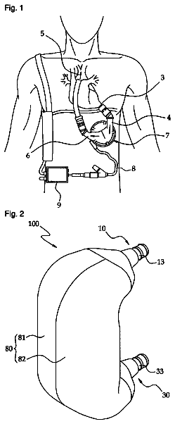
A ventricular assist device includes a case, a pair of blood bags and a squeezing unit.
US 8,535,221 B2 · Assignee: FujiFilm Corporation · Inventors: Saito; Takaaki
Sheet 1 of 12 from the published document. All sheets in the USPTO PDF
First to third lights are applied to a body cavity from a light source. The first and second lights have different wavelength ranges. Each of the first and second lights varies in absorbance in accordance with oxygen saturation of hemoglobin. The third light is a reference light used for comparison with the first and second lights. A monitoring section monitors a first light quantity ratio between the first and third lights and a second light quantity ratio between the second and third lights. A controller controls the light source such that first and second light quantity ratios reach their respective standard values. First to third data are obtained from images captured with illumination of the three lights, respectively. Vessel depth information and oxygen saturation information are obtained simultaneously from a first brightness ratio between the first and third data and a second brightness ratio between the second and third data.
1 of 12 drawing sheets so far from the published document, cropped to the drawing. Every sheet is in the USPTO PDF.
What the patent claimed, word for word. All of it is now free to use.
The present invention relates to an electronic endoscope system for obtaining vascular information from an image captured with an electronic endoscope and a method for obtaining the vascular information.
2. Description Related to the Prior Art
Diagnoses and treatments using an electronic endoscope are very common. The electronic endoscope is provided with a long insert section to be inserted into a patient's body cavity. The insert section incorporates an imaging device such as a CCD in its distal end portion. The electronic endoscope is connected to a light source apparatus. Light emitted from the light source apparatus is applied to the patient's body cavity through the distal end portion of the insert section. The imaging device in the distal end portion captures an image of an objective tissue in the body cavity while the light illuminates the body cavity. The captured image is subjected to various processes performed by the processing apparatus connected to the electronic endoscope, and then displayed on a monitor. The electronic endoscope allows an operator to observe an image of the patient's body cavity real-time, which ensures accurate diagnosis.
A white light source such as a xenon lamp is used as the light source apparatus. The xenon lamp emits white broadband light in a wavelength range from a blue region to a red region. Illuminating the body cavity with the white broadband light provides an image showing an outline of an objective tissue. However, it is difficult to clearly observe microblood vessels, deep blood vessels, a pit pattern, an uneven structure such as a recess and a protrusion. It is known that illumination of narrowband light with a wavelength limited to a specific region allows clear observation of the above body sites. It is known that various pieces of information, such as oxygen saturation of hemoglobin in a blood vessel on an objective tissue, are obtained from image data when an image is captured with the illumination of the narrowband light.
For example, in U.S. Patent Application Publication No. 2003/0176768 (corresponding to Japanese Patent No. 3559755), three kinds of narrowband lights (red, green, and blue lights) are sequentially applied to a patient's body cavity as the illumination light. During the application of each narrowband light, an image is captured. Light reaches a deeper blood vessel as its wavelength becomes longer. For example, when the blue illumination light is applied, an image is captured with its surface blood vessel emphasized. When the green illumination light is applied, an image is captured with its middle blood vessel emphasized. When the blue illumination light is applied, an image is captured with its deep blood vessel emphasized. Color image processing is performed based on the image data of each of the captured images. Accordingly, in an image produced, the surface blood vessel, the middle blood vessel, and the deep blood vessel are shown in different colors so as to be easily distinguished from each other.
In Japanese Patent No. 2648494, narrowband lights IR1, IR2, and IR3 in a near infrared region are applied. The application of the narrowband lights IR1 and IR3 changes hemoglobin absorbance of a blood vessel due to oxygen saturation. The application of the narrowband light IR2 does not change the hemoglobin absorbance. During the application of each narrowband light as the illumination light, an image is captured. Changes in brightness of the images are calculated based on the images captured with the applications of the narrowband lights IR1 and IR3 and the image captured with the application of the narrowband light IR2. The calculated changes in brightness are reflected in black-and-white or in pseudo-color to the image. The information on the oxygen saturation of hemoglobin in the blood vessel is obtained from the image.
Recently, it has been desired to perform diagnosis and the like while the vessel depth and the oxygen saturation are obtained simultaneously. The hemoglobin absorbance of a blood vessel, however, changes considerably in accordance with a wavelength of the light applied (see FIG. 3). Accordingly, it is difficult to obtain information on both the vessel depth and the oxygen saturation simultaneously.
The sequential application of the three kinds of narrowband lights (the red, green, and blue lights) provides information on the depth of a blood vessel as described in the U.S. Patent Application Publication No. 2003/0176768, for example. However, the application of three kinds of narrowband lights does not provide information on the oxygen saturation. On the other hand, the application of the narrowband light IR1, IR2, and IR3 in a near infrared region provides information on the oxygen saturation as described in the Japanese Patent No. 2648494. However, the application of narrowband lights in the near infrared region does not provide the information on the depth of the blood vessel. The information on the vessel depth and the information on the oxygen saturation cannot be obtained simultaneously even if the lights in wavelength regions including both of the wavelength regions disclosed in the U.S. Patent Application Publication No. 2003/0176768 and the Japanese Patent No. 2648494 are applied.
An object of the present invention is to provide an electronic endoscope system and a method for obtaining vascular information capable of obtaining blood depth information and oxygen saturation information simultaneously.
In order to achieve the above and other objects, an electronic endoscope system of the present invention includes an electronic endoscope, an illumination section, a controller, a signal obtaining section, and a vascular information obtaining section. The electronic endoscope has an image sensor to capture an image of an objective tissue including a blood vessel. The illumination section applies first to third illumination lights to the objective tissue. The first and second illumination lights have different wavelength ranges from each other and vary in absorbance in accordance with oxygen saturation of hemoglobin in the blood vessel. The third illumination light is a reference light used for comparison with the first and second illumination lights. The controller controls light quantities of the first to third illumination lights based on a first light quantity ratio between the light quantities of the first and third illumination lights and a second light quantity ratio between the light quantities of the second and third illumination lights. The signal obtaining section obtains first to third imaging signals outputted from the image sensor. The first to third imaging signals corresponds to respective reflection light quantities of reflection lights from the objective tissue upon application of the first to third illumination lights. The vascular information obtaining section obtains vascular information, having both oxygen saturation information of the oxygen saturation and vessel depth information of the blood vessel, based on a first brightness ratio and a second brightness ratio. The first brightness ratio is a ratio between the first and third imaging signals. The second brightness ratio is a ratio between the second and third imaging signals.
The illumination section applies the first to third illumination lights sequentially or in any combination as necessary. It is preferable that the electronic endoscope system further includes a light quantity detector for detecting light quantities of the first to third illumination lights. It is preferable that the controller controls the light quantities of the first to third illumination lights based on detected light quantities such that the first and second light quantity ratios reach respective standard light quantity ratios. It is preferable that the first and second illumination lights are narrowband lights in a blue region. It is preferable that at least one of the first and second illumination lights has a center wavelength at or below 450 nm. It is preferable that in each of the wavelength ranges of the first and second illumination lights, magnitude relation between absorbance of deoxyhemoglobin and absorbance of oxyhemoglobin is reversed in respective absorption spectra. It is preferable that the wavelength range of the first illumination light is 440.+-.10 nm and the wavelength range of the second illumination light is 470.+-.10 nm. It is preferable that the electronic endoscope system further includes a memory for storing the light quantities of the first to third illumination light and first to third image data. The light quantities of the first and third illumination lights are associated with the first to third image data, respectively. The first to third image data are generated based on the first to third imaging signals, respectively.
It is preferable that the electronic endoscope system further includes a calibration imaging signal obtaining section and a difference value storage. The calibration imaging signal obtaining section obtains first to third calibration imaging signals outputted from the image sensor in accordance with respective reflection light quantities of lights reflected by a reference object upon application of the first to third illumination lights. The reference object has a known reflection spectrum. The difference value storage stores a difference value between a first imaging signal ratio and its corresponding standard imaging signal ratio and a difference value between the second imaging signal ratio and its corresponding standard imaging signal ratio. The difference values are calculated based on the first and second imaging signal ratios. The first imaging signal ratio is a ratio between the first and third calibration imaging signals and corresponds to the first light quantity ratio. The second imaging signal ratio is a ratio between the second and third calibration imaging signals and corresponds to the second light quantity ratio. The controller controls the light quantities of the first to third illumination lights based on the difference values.
Another electronic endoscope system of the present invention includes an electronic endoscope, an illumination section, a signal obtaining section, a signal correcting section, and a vascular information obtaining section. The electronic endoscope has an image sensor for capturing an image of an objective tissue including a blood vessel. The illumination section applies a first illumination light, a second illumination light, and a third illumination light to the objective tissue. The first and second illumination lights have different wavelength ranges from each other. Each of the first and second illumination lights varies in absorbance in accordance with oxygen saturation of hemoglobin in the blood vessel. A third illumination light is a reference light used for comparison with the first and second illumination lights. The signal obtaining section obtains a first imaging signal, a second imaging signal, and a third imaging signal. The first to third imaging signals are outputted from the image sensor in accordance with respective reflection light quantities of reflection lights from the objective tissue upon application of the first to third illumination lights. The signal correcting section for correcting the first to third imaging signals based on a first light quantity ratio between the light quantities of the first and third illumination lights and a second light quantity ratio between the light quantities of the second and third illumination lights. The vascular information obtaining section obtains vascular information, having both oxygen saturation information of the oxygen saturation and vessel depth information of the blood vessel, based on a first brightness ratio and a second brightness ratio. The first brightness ratio is a ratio between a corrected first imaging signal and a corrected third imaging signal. The second brightness ratio is a ratio between a corrected second imaging signal and a corrected third imaging signal.
The illumination section applies the first to third illumination lights sequentially or in any combination as necessary. It is preferable that the electronic endoscope system further includes a light quantity detector for detecting the light quantities of the first to third illumination lights, and the signal correcting section corrects the first to third imaging signals based on a difference value between the first light quantity ratio and its corresponding standard light quantity ratio and a difference value between the second light quantity ratio and its corresponding standard light quantity ratio, and the difference values are calculated based on the light quantities detected by the light quantity detector, and the vascular information obtaining section obtains the vascular information based on the corrected first to third imaging signals.
It is preferable that the electronic endoscope system further includes a calibration imaging signal obtaining section and a difference value memory. The calibration imaging signal obtaining section obtains first to third calibration imaging signals outputted from the image sensor in accordance with respective reflection light quantities of lights reflected by a reference object upon application of the first to third illumination lights, the reference object having a known reflection spectrum. The difference value memory stores a difference value between a first imaging signal ratio and its corresponding standard imaging signal ratio and a difference value between the second imaging signal ratio and its corresponding standard imaging signal ratio. The difference values is calculated based on the first and second imaging signal ratios. The first imaging signal ratio is a ratio between the first and third calibration imaging signals and corresponds to the first light quantity ratio. The second imaging signal ratio is a ratio between the second and third calibration imaging signals and corresponds to the second light quantity ratio. The signal correcting section corrects the first to third imaging signals based on the difference values and the vascular information obtaining section obtains the vascular information based on corrected first to third imaging signals.
A method for obtaining vascular information includes an applying step, a controlling step, a signal obtaining step, and a vascular information obtaining step. In the applying step, first to third illumination lights are applied to an objective tissue having a blood vessel. The first and second illumination lights have different wavelength ranges from each other and vary in absorbance in accordance with oxygen saturation of hemoglobin in the blood vessel. The third illumination light is a reference light used for comparison with the first and second illumination lights. In the controlling step, light quantities of the first to third illumination lights are controlled based on a first light quantity ratio between light quantities of the first and third illumination lights and a second light quantity ratio between light quantities of the second and third illumination lights. In the signal obtaining step, first to third imaging signals outputted from the image sensor in accordance with respective reflection light quantities of lights reflected by the objective tissue are obtained upon application of the first to third illumination lights. In the vascular information obtaining step, vascular information, having both oxygen saturation information of the oxygen saturation and vessel depth information of the blood vessel, is obtained based on a first brightness ratio and a second brightness ratio. The first brightness ratio is a ratio between signal values of the first imaging signal and the third imaging signal. The second brightness ratio is a ratio between signal values of the second imaging signal and the third imaging signal.
The illumination section applies the first to third illumination lights sequentially or in any combination as necessary. It is preferable that the method further includes a detecting step in which light quantities of the first to third illumination lights are detected. In the controlling step, the light quantities of the first to third illumination lights are controlled such that the first light quantity ratio and the second light quantity ratio reach their respective standard light quantity ratios during the light quantity control.
It is preferable that the method further includes a calibration imaging signal obtaining step and a storing step. In the calibration imaging signal obtaining step, first to third calibration imaging signals outputted from the image sensor in accordance with respective reflection light quantities of lights reflected by a reference object upon application of the first to third illumination lights are obtained. The reference object has a known reflection spectrum. In the storing step, a difference value between a first imaging signal ratio and its corresponding standard imaging signal ratio and a difference value between the second imaging signal ratio and its corresponding standard imaging signal ratio are stored. The difference values are calculated based on the first and second imaging signal ratios. The first imaging signal ratio is a ratio between the first and third calibration imaging signals and corresponds to the first light quantity ratio. The second imaging signal ratio is a ratio between the second and third calibration imaging signals and corresponds to the second light quantity ratio.
Another method for obtaining vascular information according to the present invention includes an applying step, a signal obtaining step, a signal correction step, and vascular information obtaining step. In the applying step, first to third illumination lights are applied to an objective tissue having a blood vessel. The first and second illumination lights have different wavelength ranges from each other and vary in absorbance in accordance with oxygen saturation of hemoglobin in the blood vessel. The third illumination light is a reference light used for comparison with the first and second illumination lights. In the signal obtaining step, first to third imaging signals outputted from the image sensor are obtained. The first to third imaging signals correspond to respective reflection light quantities of reflection lights from the objective tissue upon application of the first and second illumination lights. In a signal correcting step, the first to third imaging signals are corrected based on a first light quantity ratio and a second light quantity ratio. The first light quantity ratio is a ratio between light quantities of the first and third illumination lights. The second light quantity ratio is a ratio between light quantities of the second and third illumination lights. In the vascular information obtaining step, vascular information is obtained based on a first brightness ratio and a second brightness ratio. The first brightness ratio is a ratio between signal values of a corrected first imaging signal and a corrected third imaging signal. The second brightness ratio is a ratio between signal values of a corrected second imaging signal and the corrected third imaging signal. The vascular information has both oxygen saturation information of the oxygen saturation and vessel depth information of the blood vessel.
The illumination section applies the first to third illumination lights sequentially or in any combination as necessary. It is preferable that the method further includes the detecting step and correcting step. In the detecting step, the light quantities of the first to third illumination lights are detected. In the correcting step, the first to third imaging signals are corrected based on a difference value between the first light quantity ratio and its corresponding standard light quantity ratio and a difference value between the second light quantity ratio and its corresponding standard light quantity ratio. The difference values are calculated based on the detected light quantities.
It is preferable that the method further includes a calibration imaging signal obtaining step and a storing step. In the calibration imaging step, first to third calibration imaging signals outputted from the image sensor in accordance with respective reflection light quantities of lights reflected by a reference object upon application of the first to third illumination lights are obtained. The reference object has a known reflection spectrum. In the storing step, a difference value between a first imaging signal ratio and its corresponding standard imaging signal ratio and a difference value between the second imaging signal ratio and its corresponding standard imaging signal ratio are stored. The difference value is calculated based on the first and second imaging signal ratios. The first imaging signal ratio is a ratio between the first and third calibration imaging signals and corresponds to the first light quantity ratio. The second imaging signal ratio is a ratio between the second and third calibration imaging signals and corresponds to the second light quantity ratio.
According to the present invention, the first to third illumination lights are applied. The first and second illumination lights have different wavelength ranges from each other. Each of the first and second illumination lights varies in absorbance in accordance with the oxygen saturation of hemoglobin in blood vessel. The third illumination light, being the reference light, is used for comparison with the first and second illumination lights. By the application of the first to third illumination lights, both the vessel depth information and oxygen saturation information are obtained simultaneously. By controlling the light quantities of the first to third illumination lights based on the first light quantity ratio between the light quantities of the first and third illumination lights and the second light quantity ratio between the light quantities of the second and third illumination lights, or by correcting the first to third imaging signals corresponding to the first to third illumination lights, the vessel depth information and the oxygen saturation information are determined with stability and unaffected by unstable light sources.
The above and other objects and advantages of the present invention will be more apparent from the following detailed description of the preferred embodiments when read in connection with the accompanied drawings, wherein like reference numerals designate like or corresponding parts throughout the several views, and wherein:
FIG. 1 is an external view of an electronic endoscope system according to a first embodiment of the present invention;
FIG. 2 is a block diagram of an electric configuration of the electronic endoscope system according to the first embodiment;
FIG. 3 is a graph showing spectral transmittances of a B pixel, a G pixel, and an R pixel of a color CCD and the broadband light BB and a distribution of light intensities of the first to third narrowband lights N1 to N3;
FIG. 4A is an explanatory view describing an imaging operation of a CCD in a normal mode;
FIG. 4B is an explanatory view describing an imaging operation of the CCD in a special mode;
FIG. 5 is a graph of a hemoglobin absorption coefficient;
FIG. 6 is a graph showing a correlation between a first brightness ratio S1/S3, a second brightness ratio S2/S3, a vessel depth, and oxygen saturation;
FIG. 7A is an explanatory view of a method for determining coordinates (X*, Y*) in a brightness coordinate system from first and second brightness ratios S1*/S3*, S2*/S3*;
FIG. 7B is an explanatory view of a method for determining coordinates (U*, V*) in a vascular information coordinate system corresponding to the coordinates (X*, Y*);
FIG. 8 shows a monitor on which one of the depth image and the oxygen saturation image is displayed;
FIG. 9 shows the monitor on which both the depth image and the oxygen saturation image are displayed;
FIG. 10 is the monitor on which the vessel depth information and the oxygen saturation information are simultaneously displayed as the text information;
FIG. 11 is a flowchart showing steps for calculating vessel depth-oxygen saturation information and steps for generating a depth image and an oxygen saturation image based on the information calculated;
FIG. 12 is an explanatory view of an imaging operation of a CCD according to a second embodiment of the present invention;
FIG. 13 is an explanatory view of an imaging operation of another CCD according to the second embodiment of the present invention;
FIG. 14 is an explanatory view of a CCD according to a third embodiment of the present invention; and
FIG. 15 is a block diagram of an electric configuration of an electronic endoscope system according to a fourth embodiment of the present invention.
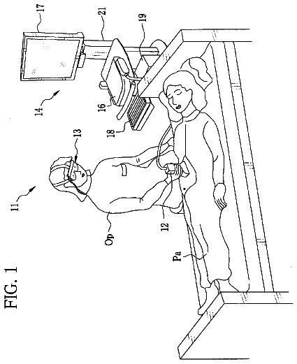
As shown in FIG. 1, an electronic endoscope system 10 according to a first embodiment of the present invention is provided with an electronic endoscope 11, a processing apparatus 12, a light source apparatus 13, and a monitor 14. The electronic endoscope 11 captures an image in a patient's body cavity. The processing apparatus 12 generates an image of an objective tissue (an object of interest) in the body cavity based on a signal obtained by the image capture. The light source apparatus 13 supplies light for illuminating the body cavity. The monitor 14 displays the image generated. The electronic endoscope 11 is provided with a flexible insert section 16 to be inserted into the body cavity, a handling section 17 provided in the basal portion of the insert section 16, and a universal cord 18. The universal cord 18 connects the handling section 17, the processing apparatus 12, and the light source apparatus 13. The processor apparatus 12 is provided with a console 23 (see FIG. 2) composed of a keyboard and a mouse for inputting an operation signal.
The insert section 16 has a bending portion 19 at its tip. The bending portion 19 has a plurality of joint pieces. Operating an angle knob 21 provided in the handling section 17 bends the bending portion 19 in horizontal and vertical directions. A distal portion 16a is provided at a distal end of the bending portion 19. The distal portion 16a incorporates an optical system and the like used for the image capture in the body cavity. Bending the bending portion 19 directs the distal portion 16a to a desired direction.
A connector 24 is attached to one end of the universal cord 18 where the processing apparatus 12 and the light source apparatus 13 are to be connected. The connector 24 is a multiple-type connector composed of a communication connector and a light source connector. The electronic endoscope 11 is detachably connected to the processing apparatus 12 and the light source apparatus 13 via the connector 24.
As shown in FIG. 2, the light source apparatus 13 is provided with a broadband light source 30, a shutter 31, a shutter driver 32, first to third narrowband light sources 33, a coupler 36, and a light source switching section 37. The light source apparatus 13 further includes a light quantity ratio monitoring section 41 and a light source controller 42. The light quantity ratio monitoring section 41 monitors a light quantity ratio among the first to third narrowband light sources 33. The light source controller 42 controls the first to third narrowband light sources 33.
The broadband light source 30 is a xenon lamp, a white LED, a microwhite light source, or the like. The broadband light source 30 emits broadband light BB in a wavelength range from red to blue (approximately from 470 nm to 700 nm). The broadband light source 30 is kept turned on while the electronic endoscope 11 is in use. The broadband light BB emitted from the broadband light source 30 is collected by a condenser lens 39 into a broadband optical fiber 40.
The shutter 31 is provided between the broadband light source 30 and the condenser lens 39. The shutter 31 is movable between an insert position and a retract position. In the insert position, the shutter 31 is inserted in an optical path of the broadband light BB to block the broadband light BB. In the retract position, the shutter 31 retracts from the insert position to allow the broadband light BB to enter the condenser lens 39. The shutter driver 32 is connected to a controller 59 in the processing apparatus 12, and controls the shutter 31 based on an instruction from the controller 59.
The first to third narrowband light sources 33 to 35 emit first to third narrowband lights N1 to N3 as the first to third illumination lights, respectively. Each of the narrowband lights N1 to N3 has a wavelength range within a narrowband. Each of the first to third narrowband light sources 33 to 35 is composed of a semiconductor light source, for example, a laser diode or an LED. The first narrowband light source 33 generates the first narrowband light N1 in a wavelength range of 440.+-.10 nm, preferably 445 nm. The second narrowband light source 34 generates the second narrowband light N2 in a wavelength range of 470.+-.10 nm, preferably 473 nm. The third narrowband light source 35 generates the third narrowband light N3 in a wavelength range of 400.+-.10 nm, preferably 405 nm. The first to third narrowband, lights N1 to N3 are narrowband lights (hereinafter referred to as the blue narrowband lights) in the blue region. Each of the first and second narrowband lights N1 and N2 varies in absorbance in accordance with oxygen saturation of hemoglobin in a blood vessel, which will be described later. The third narrowband light N3 is used as reference light to obtain a reference signal. The reference signal is used for comparison with an imaging signal corresponding to the first narrowband light N1 and an imaging signal corresponding to the second narrowband light N2.
Each of the first to third narrowband light sources 33 to 35 is connected to the light source controller 42. The light source controller 42 controls the first to third narrowband light sources 33 to 35 to adjust the light quantity of each of the first to third narrowband lights N1 to N3 within a predetermined range. The first to third narrowband light sources 33 to 35 are connected to first to third narrowband optical fibers 33a to 35a, respectively. The first narrowband light N1 from the first narrowband light source 33 is incident on the first narrowband optical fiber 33a. The second narrowband light N2 from the second narrowband light source 34 is incident on the second narrowband optical fiber 34a. The third narrowband light N3 from the third narrowband light source 35 is incident on the third narrowband optical fiber 35a.
The coupler 36 connects the broadband optical fiber 40 and the first to third narrowband optical fibers 33a to 35a to the light guide 43 of the electronic endoscope 11. The coupler 36 allows the broadband light BB to enter the light guide 43 through the broadband optical fiber 40. The coupler 36 allows the first to third narrowband lights N1 to N3 to enter the light guide 43 through the respective first to third narrowband optical fibers 33a to 35a.
The light source switching section 37 is connected to the controller 59 in the processing apparatus. Based on an instruction from the controller 59, the light source switching section 37 turns on or off each of the first to third narrowband light sources 33 to 35. In the first embodiment, when the electronic endoscope system 10 is set to a normal mode, the broadband light BB is applied to the patient's body cavity to capture a normal light image while the first to third narrowband light sources 33 to 35 are turned off. On the other hand, when the electronic endoscope system 10 is set to a special mode, the application of the broadband light BB to the body cavity is stopped, and each of the first to third narrowband light sources 33 to 35 is sequentially turned on to capture a special light image.
To be more specific, firstly, the light source switching section 37 turns on the first narrowband light source 33. An image of an objective tissue is captured while the first narrowband light N1 is applied to the body cavity. When the image capture is completed, the controller 59 issues an instruction to switch the light source. Thereby, the light source switching section 37 turns off first narrowband light source 33, and then turns on the second narrowband light source 34. When image capture with the application of the second narrowband light N2 to the body cavity is completed, the light source switching section 37 turns off the second narrowband light source 34, and then turns on the third narrowband light source 35. When image capture with the application of the third narrowband light N3 to the body cavity is completed, the light source switching section 37 turns off the third narrowband light source 35.
The light quantity monitoring section 41 monitors a light quantity ratio among the first to third narrowband lights N1 to N3. To monitor the light quantity ratio, the light quantity detectors 33b to 35b are attached to the first to third narrowband optical fibers 33a to 35a, respectively. The first to third narrowband lights N1 to N3 are guided to the first to third narrowband optical fibers 33a to 35a, respectively. The light quantity detectors 33b to 35b detect the light quantities of the first to third narrowband lights N1 to N3, respectively. The light quantity signal values detected by the light quantity detectors 33b to 35b are sent to the light quantity monitoring section 41 and then to a digital signal processor (hereinafter abbreviated as the DSP) 55 of the processing apparatus 12. The light quantity monitoring section 41 monitors the light quantity ratio among the first to third narrowband lights N1 to N3 based on the light quantity signal values.
In this embodiment, the light quantity monitoring section 41 monitors a first light quantity ratio L1/L3 and a second light quantity ratio L2/L3. The first light quantity ratio L1/L3 is a ratio between a light quantity L1 of the first narrowband light N1 and a light quantity L3 of the third narrowband light N3. The second light quantity ratio L2/L3 is a ratio between a light quantity L2 of the second narrowband light N2 and the light quantity L3 of the third narrowband light N3. In the monitoring, a difference value between the first light quantity ratio L1/L3 being monitored and a predetermined first standard light quantity ratio, and a difference value between the second light quantity ratio L2/L3 being monitored and a predetermined second standard light quantity ratio are obtained. The difference values are sent to the light source controller 42.
The light source controller 42 controls the first to third narrowband light sources 33 to 35 based on the difference values from the light quantity monitoring section 41. The light source controller 42 controls the light quantities of the first narrowband light N1 emitted from the first narrowband light source 33, the second narrowband light N2 emitted from the second narrowband light source 34, and the third narrowband light N3 emitted from the third narrowband light source 35 such that the first light quantity ratio L1/L3 stays within the first standard light quantity ratio and the second light quantity ratio L2/L3 stays within the second standard light quantity ratio. Each of the first and second standard light quantity ratios is predetermined before the use of the electronic endoscope, for example, at the time of shipping or regular maintenance of the electronic endoscope system. The first and second standard light quantity ratios are stored in an internal memory such as a ROM or a RAM in the controller 59, for example.
In this embodiment, the first light quantity ratio L1/L3 and the second light quantity ratio L2/L3 are monitored for the following reasons. In this embodiment, a vessel depth and the oxygen saturation are obtained simultaneously based on the comparison (value comparison) between first and second brightness ratios S1/S3 and S2/S3, which will be described later. The first brightness ratio S1/S3 is obtained from images captured with the illumination of the first and third narrowband lights N1 and N3, respectively. The second brightness ratio S2/S3 is obtained from images captured with the illumination of the second third narrowband lights N2 and N3, respectively. The first brightness ratio S1/S3 corresponds to the first light quantity ratio L1/L3. The second brightness ratio S2/S3 corresponds to the second light quantity ratio L2/L3. Accordingly, when the light quantity ratios, namely, the differences in the light quantities among the first to third narrowband light sources 33 to 35 fluctuate, noise caused by the fluctuation contaminates the first brightness ratio S1/S3 and the second brightness ratio S2/S3. As a result, the vessel depth and the oxygen saturation cannot be obtained accurately. To prevent the noise, the first and second light quantity ratios L1/L3 and L2/L3 are controlled to be kept or adjusted to constant values (the first and second standard light quantity values), respectively. Thus, the first and second brightness ratios S1/S3 and S2/S3 are obtained accurately without influence of the noise, and as a result, the vessel depth and the oxygen saturation are determined accurately.
The light quantity ratio among the first to third narrowband lights N1 to N3 is preferably within the order of .+-.2% relative to a standard light quantity ratio for the following reason. For example, when the oxygen saturation is calculated using three kinds of wavelengths (405 nm, 445 nm, and 473 nm), a change in a light quantity ratio 473 nm/445 nm corresponding to a 20% change in the oxygen saturation is typically a little over 10% according to findings from imaging experiments of animal digestive mucosa and human lip mucosa. To calculate the change with stability and accuracy, the light quantity ratio among the first to third narrowband lights N1 to N3 needs to be controlled within the order of .+-.2% relative to the standard light quantity in consideration of hypoxic condition or low oxygen level caused by cancer.
The electronic endoscope 11 is provided with a light guide 43, a CCD 44, an AFE (analog front end) 45, and an imaging controller 46. The light guide 43 is, for example, a large core optical fiber or a bundle fiber, and its input end is inserted into the coupler 36 in the light source apparatus 13 and its exit end is directed to an illumination lens 48. The light guide 43 delivers the light emitted from the light source apparatus 13 to the illumination lens 48. The light incident on the illumination lens 48 is applied to the body cavity through an illumination window 49 attached to an end surface of the distal portion 16a. The broadband light BB and the first to third narrow band lights N1 to N3 reflected from the body cavity are incident on an imaging lens 51 through a capture window 50 attached to the end surface of the distal portion 16a.
The light from the condenser lens 51 is incident on an imaging surface 44a of the CCD 44. The CCD photoelectrically converts the incident light into signal charge and accumulates the signal charge, and reads out the accumulated signal charge as an imaging signal. The imaging signal is sent to the AFE 45. The CCD 44 is a color CCD. On the imaging surface 44a, red, green, and blue (R, G, and B) pixels are arranged in matrix. The R pixel is provided with a red filter. The G pixel is provided with a green filter. The B pixel is provided with a blue filter.
The description continues in the full USPTO document.
About 6,391 words. The USPTO PDF has it with every drawing.
Fees are due 3.5, 7.5 and 11.5 years after grant. This patent expired on September 17, 2025, so the fee marked "not paid" was the one that went unpaid.
ELECTRONIC ENDOSCOPE SYSTEM AND METHOD FOR OBTAINING VASCULAR INFORMATION
Filed Aug 2011 · published Mar 2012Electronic endoscope system and method for obtaining vascular information
Filed Aug 2011 · granted Sep 2013Earlier publications, parents and continuations. None of them can still be enforced, or this patent would not be listed.
Prior art cited by the examiner or applicant. Useful when you check your own idea for novelty.
Everything on this page comes from the documents linked above.