 Lapsed, fee not paid3 drawings
Lapsed, fee not paidSolo inventor
Powered converter dolly and securing device
US 8,534,694 B2 · Inventors: Banwart; Donald D.
Overview
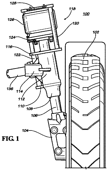
Sheet 1 of 45 from the published document. All sheets in the USPTO PDF
Abstract From the patent
A powered converter dolly for movement and attachment of trailers is provided. The dolly comprises a conventional converter dolly having a retractable landing gear assembly mounting wheels attached to the drawbar. The dolly has a power supply and operates as a towing device. The landing gear assembly provides steering for the dolly as well as motive power from a motor connected to the landing gear wheels. Alternatively, the wheels of the dolly may be powered for providing motion to the dolly. The dolly further comprises several attachment devices for securing the dolly to an intermodal railcar, including alternative hydraulic, mechanical, and electrically-powered tie down devices. A trolley movable along a railcar is provided for securing the dolly or trailer to the railcar and includes a hitch component for selectively interconnecting to a hitch component on the dolly or trailer.
Why it's free to use
- The USPTO Official Gazette of November 11, 2025 lists it as expired on September 17, 2025 for an unpaid maintenance fee.
- It isn't on any reinstatement notice published since.
- Its 1 US relative has also lapsed, expired or never issued.
- We check US rights only. Check foreign counterparts before selling abroad.
FiledMay 27, 2010
GrantedSeptember 17, 2013
Expired (fee)September 17, 2025
Application number12/789140
Classification (CPC)B61D3/187 +3 more
Length8 claims · 55 pages
Background From the patent
A converter dolly is used to attach a load-trailer to a lead-trailer or tractor-trailer assembly thereby enabling a tractor-trailer assembly to pull two or more trailers. Converter dollies generally consist of a frame having one or two axles, a coupling member for attachment to a lead-trailer, and a fifth wheel plate attached to the top of the frame above the axles for engaging the kingpin of a load-trailer. The conventional method of assembling dollies and load-trailers requires one or more people to manually maneuver an uncoupled dolly around a trailer yard and into contact with an uncoupled trailer. After the load-trailer dolly assembly is created, a tractor-trailer assembly is backed up to it for joining of the two assemblies. This procedure is repeated for each load-trailer dolly assembly that is attached to a lead trailer. The conventional method of assembling trailers and dollies
Drawings 45
1 of 45 drawing sheets so far from the published document, cropped to the drawing. Every sheet is in the USPTO PDF.
Figures as described
- FIG. 2 is a plan view of the converter dolly of FIG. 1
- FIG. 3 is an elevation view of the converter dolly of FIG. 1 with the landing gear extended
- FIG. 4 is an elevational view of the converter dolly of FIG. 1 coupled to a load-trailer and a leading trailer, with the dolly landing gear retracted
- FIG. 5 is an elevational view of the converter dolly of FIG. 4 attached to an intermodal railroad flatcar
- FIG. 6A is an enlarged elevational view of the tie down mechanism taken generally within circle 6A in FIG. 5
- FIG. 6B is a sectional view of a tie down mechanism taken along the line 6B in FIG. 6A
- FIG. 6C is an alternative tie down mechanism
- FIG. 6D is another alternative tie down mechanism
- FIG. 6E is another alternative tie down mechanism
- FIG. 6F is another alternative tie down mechanism
- FIG. 10 is the dolly of FIG. 9 connecting to a trailer
- FIG. 11 is the dolly of FIG. 9 lifting a trailer for transport
Claims 8 total, 1 independent
What the patent claimed, word for word. All of it is now free to use.
- 1Independent claimA dolly for moving a trailer having a first hitch component, which dolly comprises: a frame having front and back ends; a drawbar extending from said frame front end; an axle assembly depending from said frame, said axle assembly having a ground engaging wheel; a landing gear assembly pivotally attached to said drawbar, said landing gear assembly comprised of: (a) a steering mechanism; (b) a leg having first and second ends, said first end connected to said drawbar; and (c) a landing gear wheel mounted to said leg second end, said wheel being connected to said steering mechanism; said landing gear assembly having a lowered position whereby said landing gear wheel engages the ground, and having a raised position whereby said landing gear wheel is proximate to said drawbar; and a second hitch component selectively interconnectable with the first hitch component, said second hitch component disposed on top of said frame.
- 2The dolly of claim 1, including: a drive motor operably connected to one of said axle assembly wheel or said landing gear wheel; and a drive motor power source operably connected to said motor.
- 3The dolly of claim 2, wherein: said steering mechanism includes a steering actuator for rotating said leg; and a steering mechanism power source operably connected to said steering actuator.
- 4The dolly of claim 3, including: a landing gear actuator, said landing gear actuator including a piston and cylinder unit pivotally connected to said frame and said leg for positioning said landing gear assembly between a lowered position and a raised position; and a landing gear actuator power source operably connected to said landing gear actuator.
- 5The dolly of claim 3, including: said leg comprising a piston and cylinder unit movable between an extended position and a retracted position; a leg actuator operably connected to said leg for extending and retracting said leg; and a leg actuator power source operably connected to said leg actuator.
- 6The dolly of claim 3, further including: a braking system, said braking system operably connected to said axle assembly; and a braking system power source operably connected to said braking system.
- 7The dolly of claim 6 wherein said dolly-to-trailer hitch second component is movable vertically with respect to said frame.
- 8The dolly of claim 1, including: a pitch actuator located on said frame; said pitch actuator attached to said frame and contacting said dolly-to-trailer hitch second component; and a pitch actuator power source operably connected to said pitch actuator.
Description
Background of the invention
1. Field of the invention
The present disclosed technology relates generally to trailer transportation and securing devices, and in particular a converter dolly that is self-powered for movement around a trailer yard and for movement into contact with a lead-trailer and a load-trailer, and a trolley that rolls within a channel in the middle of a railroad flatcar capable of securing a load thereto.
2. Description of the related art
A converter dolly is used to attach a load-trailer to a lead-trailer or tractor-trailer assembly thereby enabling a tractor-trailer assembly to pull two or more trailers. Converter dollies generally consist of a frame having one or two axles, a coupling member for attachment to a lead-trailer, and a fifth wheel plate attached to the top of the frame above the axles for engaging the kingpin of a load-trailer. The conventional method of assembling dollies and load-trailers requires one or more people to manually maneuver an uncoupled dolly around a trailer yard and into contact with an uncoupled trailer. After the load-trailer dolly assembly is created, a tractor-trailer assembly is backed up to it for joining of the two assemblies. This procedure is repeated for each load-trailer dolly assembly that is attached to a lead trailer.
The conventional method of assembling trailers and dollies creates dangerous conditions for people maneuvering the dollies and attaching them to a tractor-trailer, and for personnel around backward moving tractor-trailer assemblies. A great deal of manual effort is required of an operator to lift the front end of the dolly off the ground and keep the dolly under control when maneuvering it around the trailer yard coupling it to a load-trailer, or assisting with coupling the dolly to a lead-trailer.
Problems may be encountered when transporting trailers, and multiple linked dolly and trailer assemblies on railcars, and properly securing them to the railcar due to the securing points on the dollies and trailers being in unpredictable locations.
What is needed is the ability to maneuver dollies into alignment and coupling with load-trailers, and the ability to move the load-trailer dolly assembly into alignment and coupling with a lead-trailer, without requiring undue effort by an operator, or putting the operator and other personnel into a dangerous situation. In addition, what is needed is the ability to secure multiple trailer, and dolly and trailer assemblies to a railroad flatcar for intermodal transportation.
Heretofore there has not been available a converter dolly with the advantages and features of the disclosed subject matter.
Summary of the invention
A self-powered converter dolly suitable for highway transportation is provided for moving trailers around a yard, and for joining trailers with lead-trailers. The dolly includes a frame having one or more axles and wheels, a fifth wheel, and a drawbar and ring coupling. The drawbar may be fixed in relation to the dolly or pivot. A powered, steerable landing gear is attached to the drawbar of the dolly. The landing gear has a steering control module with a hydraulic leg extending therefrom attaching wheels. The steering control module controls the direction of the landing gear wheels, and the extending and retracting of the hydraulic leg for positioning the dolly ring coupling at the right height for connection with a lead-trailer. The wheels are connected to a motor that provides rotational movement to the wheels enabling the dolly to move under its own power, and to move an attached trailer around a trailer yard. The motor on the landing gear can be either hydraulically-powered or electrically-powered with the respective power source being located on the dolly. In addition, the dolly provides a compressed air source to operate the air brakes on the dolly and the load-trailer.
The dolly is controlled by an operator using a remote control enabling the operator to remain in a safe location away from the dolly and trailer when moving the dolly, connecting the dolly to a load-trailer, and when connecting a dolly and load-trailer assembly to a lead trailer. Moreover, the self-powered converter dolly allows one operator to safely maneuver the dolly around the trailer yard, and to couple the dolly and trailers together avoiding excessive physical strain and injury to personnel.
The steerable landing gear may be used with a dolly having power supplied to the wheels on the axles of the dolly instead of power supplied to the landing gear wheels. For dollies having only one axle, the pitch of the fifth wheel can be adjusted by a hydraulic cylinder that pushes the wheels of the landing gear into the ground allowing the wheels to have traction. Alternatively, the fifth wheel can be provided with a hydraulic scissor lift permitting an operator to move trailers around a trailer yard without needing to retract the landing gear on the trailer.
The dolly may be used with intermodal transportation systems utilizing railway flatcars providing an attachment point for securing the dolly to the railcar. The dolly may be secured to the railcar using a tie down such as a chain, ratchet load binder, hydraulic cylinder, a winch and cable, or a hitch and receiver component.
Alternatively a trolley system having a trolley with an adjustable receiver, and movable along the length of a railcar may be used to secure a dolly or trailer to an intermodal railcar. The trolley moves within a trolley guide attached to the railcar. The trolley is maneuvered into a position for attachment to a dolly or trailer and immobilized by inserting a pin into a hole in the trolley that aligns with a hole in the trolley guide. A circular receiver is then raised to the appropriate height to engage a circular hitch component attached to the dolly and is secured thereto. The receiver may then be further adjusted to prevent further movement of the dolly connected thereto. The trolley is also adapted to provide a fifth wheel type receiver for securing a trailer having a kingpin to a railcar. The trolley is further provided with several mechanisms and actuators for raising and lowering the receiver into position with a hitch.
Brief description of the drawings
The drawings constitute a part of this specification and include exemplary embodiments of the invention illustrating various objects and features thereof, wherein like references are generally numbered alike in the several views.
FIG. 1 is a perspective view of a powered converter dolly embodying principles of the disclosed subject matter where the drawbar pivots on the dolly frame, and the wheels on the landing gear are the powered drive wheels.
FIG. 2 is a plan view of the converter dolly of FIG. 1.
FIG. 3 is an elevation view of the converter dolly of FIG. 1 with the landing gear extended.
FIG. 4 is an elevational view of the converter dolly of FIG. 1 coupled to a load-trailer and a leading trailer, with the dolly landing gear retracted.
FIG. 5 is an elevational view of the converter dolly of FIG. 4 attached to an intermodal railroad flatcar.
FIG. 6A is an enlarged elevational view of the tie down mechanism taken generally within circle 6A in FIG. 5.
FIG. 6B is a sectional view of a tie down mechanism taken along the line 6B in FIG. 6A.
FIG. 6C is an alternative tie down mechanism.
FIG. 6D is another alternative tie down mechanism.
FIG. 6E is another alternative tie down mechanism.
FIG. 6F is another alternative tie down mechanism.
FIG. 7 is an alternative embodiment of a powered converter dolly embodying the principles of the disclosed subject matter where the wheels on the dolly axles are the powered drive wheels.
FIG. 8 is an alternative embodiment of a powered converter dolly embodying the principles of the disclosed subject matter where the drawbar has an extendable hydraulic jack.
FIG. 9 is an alternative embodiment of a powered converter dolly embodying the principles of the disclosed subject matter where the fifth wheel is hydraulically actuated showing the dolly backing under a load-trailer.
FIG. 10 is the dolly of FIG. 9 connecting to a trailer.
FIG. 11 is the dolly of FIG. 9 lifting a trailer for transport.
FIG. 12 is a perspective view of an alternative embodiment of a powered converter dolly embodying the principles of the disclosed subject matter where the drawbar is integrated with the dolly frame, and the wheels on the landing gear are the powered drive wheels.
FIG. 13 is a plan view of the converter dolly of FIG. 12.
FIG. 14 is an elevation view of the converter dolly of FIG. 12 with the landing gear extended.
FIG. 15 is an elevational view of the converter dolly of FIG. 12 coupled to a load-trailer and a leading trailer, with the dolly landing gear retracted.
FIG. 16 is an elevation view of the converter dolly of FIG. 15 attached to an intermodal railroad flatcar.
FIG. 17A is an enlarged elevational view of the tie down mechanism taken generally within circle 15A in FIG. 16.
FIG. 17B is an alternative tie down mechanism.
FIG. 17C is another alternative tie down mechanism.
FIG. 17D is another alternative tie down mechanism.
FIG. 17E is another alternative tie down mechanism.
FIG. 18 is an alternative embodiment of a powered converter dolly embodying the principles of the disclosed subject matter where the wheels on the dolly axle are the powered drive wheels.
FIG. 19 is an alternative embodiment of a powered converter dolly embodying the principles of the disclosed subject matter where the drawbar has an extendable hydraulic jack.
FIG. 20 is a perspective view of the trolley system mounted on a railcar embodying principles of the disclosed subject matter.
FIG. 21 is a perspective view of the trolley of FIG. 20.
FIG. 22 is an elevational view of the dolly connected to a trailer on a railcar, and the trolley connected to the dolly.
FIG. 23 is an enlarged elevational view of the trolley connected to the dolly taken generally within circle 23 in FIG. 22.
FIG. 24 is an enlarged elevational view of the trolley connected to the dolly taken generally within circle 24 in FIG. 22.
FIG. 25 is a plan view of the trolley connected to a dolly on a railcar of FIG. 22.
FIG. 26 is an enlarged plan view of the trolley connected to a dolly on a railcar taken generally within circle 26 in FIG. 25.
FIG. 27 is a sectional view of the trolley and dolly on a railcar taken along the line 27 in FIG. 22.
FIG. 28 is an elevational view of an alternative embodiment trolley system embodying principles of the disclosed subject matter whereby the trolley is supporting a trailer with a fifth wheel trailer stand.
FIG. 29 is an elevational view of an alternative embodiment trolley system embodying principles of the disclosed subject matter whereby the trolley is securing a tractor with an adapter and chains.
FIG. 30 is an elevational view of the adapter without chains.
FIG. 31 is a plan view of the adapter without chains.
FIG. 32 is a sectional view of the adapter along the line 32 in FIG. 31.
FIG. 33 is an elevational view of an alternative embodiment trolley system embodying principles of the disclosed subject matter whereby the trolley is securing a tractor using a mount secured to the frame.
FIG. 34 is an elevational view of an alternative embodiment trolley system embodying principles of the disclosed subject matter whereby the trolley is supporting a trailer with a stanchion.
FIG. 35 is a perspective view of an alternative embodiment trolley system embodying principles of the disclosed subject matter whereby the trolley is using a scissor lift to raise and lower an adjustable hitch.
FIG. 36 is an elevational view of the trolley system of FIG. 35.
FIG. 37 is a plan view of the trolley of FIG. 35.
FIG. 38 is a perspective view of an alternative embodiment trolley system embodying principles of the disclosed subject matter whereby the trolley is using a scissor lift to raise and lower a mini fifth wheel hitch.
FIG. 39 is an elevational view of the trolley system of FIG. 38.
FIG. 40 is a plan view of the trolley of FIG. 38.
Description of the preferred embodiment
I. Introduction and Environment
As required, detailed aspects of the disclosed subject matter are disclosed herein; however, it is to be understood that the disclosed aspects are merely exemplary of the invention, which may be embodied in various forms. Therefore, specific structural and functional details disclosed herein are not to be interpreted as limiting, but merely as a basis for the claims and as a representative basis for teaching one skilled in the art how to variously employ the present invention in virtually any appropriately detailed structure.
Certain terminology will be used in the following description for convenience in reference only and will not be limiting. For example, up, down, front, back, right and left refer to the invention as orientated in the view being referred to. The words, "inwardly" and "outwardly" refer to directions toward and away from, respectively, the geometric center of the aspect being described and designated parts thereof. Forwardly and rearwardly are generally in reference to the direction of travel, if appropriate. Said terminology will include the words specifically mentioned, derivatives thereof and words of similar meaning.
II. Embodiment of the Powered Converter Dolly 2
Referring to the drawings in more detail, the reference numeral 2 generally designates a powered converter dolly suitable for highway transportation embodying the principles of the disclosed subject matter. The dolly 2 generally consists of a rectangular frame 4 having one or more axle assemblies 18 depending therefrom, and mounting a hitch component 50, such as a fifth wheel. An independent drawbar assembly 60 extends forward from the frame 4 and terminates at a ring coupling 70. A steerable landing gear assembly 82 is attached to the drawbar assembly 60 providing powered movement and controlling the direction of movement of the dolly 2. The dolly 2 may be attached to an object, such as a load-trailer 106, for moving the trailer 106 around a trailer yard, or to connect the trailer 106 to a lead-trailer 105.
Referring to FIGS. 1-6F, an embodiment of the dolly 2 is shown and described having two axle assemblies 18 depending therefrom including wheels 28 and air brakes, and a powered, steerable landing gear assembly 82 attached to a movable drawbar assembly 60. Referring to FIGS. 1-3, the dolly 2 is shown freestanding with the drawbar assembly 60 releasably secured to the frame 4, and the landing gear assembly 82 in an extended position with landing gear wheels 98 engaging the ground.
The dolly 2 frame 4 may be manufactured from metal, preferably steel, and is generally rectangular in configuration having opposite side rails 6 extending forward and rearward along the length of the frame 4. The side rails 6 are joined at the front end by a front rail 8, and joined at the rear end by a rear rail 10 using a secure connection such as a weld, or by fasteners such as bolts. Cross members 12 span between the side rails 6 adding rigidity to the frame 4, and permit mounting of the hitch component 50, and accessories. A pair of axle assemblies 18 each having four ground engaging wheels 28 and air-powered brakes, depend from the frame 4. The second hitch component 50 fifth wheel comprises a generally circular metal pickup plate 52 having an elongated, triangular-shaped slot 54 open at the rear for aligning a hitch component 114 such as the kingpin of a trailer 106 with the pickup plate 52. The pickup plate 52 is pivotally mounted to the frame 4 by brackets 14, 15 allowing the pickup plate 52 to pitch forward or backward as needed to engage the hitch component 114. The rear of the frame 4 may contain inclined ramps 16 for properly guiding a trailer 106 into engagement with the hitch component 50. The front of the frame 4 has a pair of brackets 13 for rotatably mounting the drawbar assembly 60 to it.
The drawbar assembly 60 is manufactured from metal, preferably steel, and is generally triangular in configuration. The drawbar assembly 60 has two side rails 67 originating from the ends of a cross member 68 located nearest the frame 4, and extends forward terminating at a ring coupling 70. The ring coupling 70 is mounted at the forward most end of the dolly 2 for engagement with a coupling 110 on a lead-trailer 105. The coupling 110 may include, but is not limited to a pintle hook coupling or a combination ball hitch. Lead-trailers 105 can have couplings 110 located at different heights above the ground. Therefore, the drawbar assembly 60 of the dolly 2 is rotatably mounted to the frame 4 by brackets 62. Rotation of the drawbar assembly 60 with respect to the frame 4 enables engagement of the ring coupling 70 to couplings 110 located at different heights above the ground. Each of the brackets 13, 62 have removable lock-out pins 66 for preventing rotation of the drawbar assembly 60 with respect to the frame 4. Preventing rotation of the drawbar assembly 60 allows rigid engagement of the landing gear assembly 82 with the ground, described in more detail below. Safety chains 72 located adjacent to the ring coupling 70 may be attached to a leading trailer 105 for added safety in case the trailer 105 and dolly 2 become uncoupled.
The landing gear assembly 82 is rotatably attached to the drawbar assembly 60 between the side rails 67 by a pivot shaft 92, and generally consists of a steering control module 84 having a telescoping leg 94 projecting therefrom. Ground engaging wheels 98 at the distal end of the leg 94, are powered by a drive motor 100 that causes the wheels 98 to rotate in both a clockwise and counterclockwise direction to provide movement to the dolly 2. The type of motor 100 used may include, but is not limited to an electrically-powered, or hydraulically-powered motor. The steering control module 84 contains an actuator (not shown) for rotating the leg 94 and wheels 98 about a vertical axis for steering the dolly 2, and an actuator (not shown) for extending and retracting the telescopic leg 94. The aforementioned actuators may include, but are not limited to an electrical actuator or a hydraulic actuator. Another actuator 88 extends between the leg 94 and cross member 68 for moving the landing gear assembly 82 between an extended and retracted position. The aforementioned actuator 88 may include, but is not limited to an electric, hydraulic, or pneumatic actuator, preferably a hydraulic actuator. The actuator 88 attaches to the leg 94 and cross member 68 by brackets 96, 90, respectively.
The dolly 2 is self-powered, providing power from one or more of the following power sources: hydraulic power from a hydraulic pump 44 and hydraulic reservoir 46; electrical power from a generator 38 and rechargeable batteries 36; and compressed air from an air compressor 30 and an air tank 32. Hydraulic power may be provided to: the actuator 88 to extend and retract the landing gear assembly 82 between a ground-engaging position and a transportation position; the steering control module 84 to power the actuator that extends and retracts the telescopic leg 94, and the actuator that rotates the leg 94 and wheels 98 for steering the dolly; and the drive motor 100 that provides movement to the wheels 98 for moving the dolly 2. Electrical power is provided to operate the hydraulic pump 44, air compressor 30, and to recharge the batteries 36. Alternatively, electrical power may be provided to electrical actuators in the steering control module 84, to the actuator 88 on the leg 94, or to an electrical drive motor 100. The dolly 2 may incorporate any combination of hydraulic, pneumatic or electrical actuators or motors 100 as deemed necessary for a particular application. Compressed air may be provided to: the actuator 88 on the leg 94; the air brake system of the dolly 2; and for connection to the air-brake system of the load-trailer 106 for releasing the air brakes without the need for the trailer 106 to be connected to a tractor.
Referring to FIG. 3, the dolly 2 is shown connected to a load-trailer 106. The dolly 2 has a remote control 102 containing a microcontroller and switches for controlling operation of: the landing gear assembly 82; actuator 88; the actuators in the leg 94 and steering control module 84; dolly 2 air brakes; and the hydraulic, pneumatic, or electrical power sources. The remote control 102 may include a safety feature that requires the operator to use both hands to operate the device, and an emergency off feature whereby the operator can cease all movement and activity of the dolly 2 and load-trailer 106 by rapidly engaging the air brakes of both. When not in use, the remote control 102 is securely stored within a storage box 74 located on the dolly 2. The storage box 74 has a lid 76 that opens on hinges 78 by lifting on a handle 80. A lengthy cord 104 connects the remote control 102 to the dolly 2 enabling an operator to position themselves out of danger, or into a better vantage point, when maneuvering the dolly 2 or an attached trailer 106.
The dolly 2 is prepared for use in maneuvering a trailer 106 by inserting the lock-out pins 66 into the brackets 13, 62 to secure the drawbar assembly 60 to the frame 4 preventing their rotation thereabout. A rigid connection between the drawbar assembly 60 and frame 4 enables the wheels 98 of the landing gear assembly 82 to have fraction with the ground. Using the remote control 102, an operator powers up the dolly 2 and extends the actuator 88 positioning the landing gear assembly 82 perpendicular to the drawbar assembly 60, and the wheels 98 in contact with the ground. The motor 100 rotates the wheels 98 and moves the dolly 2 in the direction the wheels 98 are pointing. The dolly 2 is maneuvered underneath the trailer 106 enabling engagement of the hitch component 50 with the bearing plate 112. The dolly 2 air brakes are then engaged. A supply line 65, providing an electrical and air connection between the dolly 2 and trailer 16, is connected allowing the operator to engage and disengage the air brakes on the trailer 106 using the air tank 32 on the dolly 2. Once the operator releases the air brakes on the trailer 106 and dolly 2, the motor 100 provides movement to the dolly 2 permitting the dolly 2 maneuver the trailer 106 around for repositioning or to connect the dolly 2 and trailer 106 assembly to a lead-trailer 105. During movement, the dolly 2 and trailer 106 assembly can be stopped using either the air brakes on the dolly 2 or the trailer 106.
Referring to FIG. 4, the dolly 2 is shown connected to a lead-trailer 105 with the landing gear assembly 82 in the highway transportation position. An operator aligns and connects the dolly 2 to a lead trailer 105 by positioning the ring coupling 70 in close proximity to the coupling 110 located on the bumper 108 of a lead trailer 105. The operator engages the air brakes of the load-trailer 106. The lock-out pins 66 are then removed and the leg 94 can retract to lower the ring coupling 70 onto a coupling 110 that is positioned low on the bumper 108, or the leg 94 can be extended to raise the ring coupling 70 up to a coupling 110 that is positioned high on the bumper 108. When the ring coupling 70 is securely engaged within the coupling 110, the safety chains 72 are connected to the bumper 108, and a supply line 64 is connected between the lead trailer 105 and the dolly 2 providing an electrical and air connection between the two trailers 105, 106. The landing gear assembly 82 is removed from contact with the ground by retracting the actuator 88 thereby rotating the assembly 82 until the wheels 98 are underneath the rear of the drawbar assembly 60. This positioning permits the necessary clearance between the ground and the wheels 98 when the trailers 105, 106 and dolly 2 are traveling roadways. The remote control 102 is returned to the storage box 74 during highway transportation. An electrical connection between the lead-trailer 105 and the dolly 2 can provide power for recharging the batteries 36 between uses.
The dolly 2 is disengaged from the lead trailer 105 by disconnecting the safety chains 72 and the supply line 64 between the lead trailer 105 and the dolly 2, powering up the dolly 2, engaging the air brakes of the following trailer 106 using the air supply from the dolly 2, extending the actuator 88 until the wheels 98 are in contact with the ground, and extending the leg 94 to raise the ring coupling 70 off of the coupling 110. The height of the drawbar assembly 60 is adjusted by extending and retracting the leg 94 to permit re-installation of the lock-out pins 66. Once there is a rigid connection between the drawbar assembly 60 and the frame 4, the operator can engage the motor 100 to move the dolly and trailer 106 away from the lead trailer 105.
Referring to FIGS. 5-6B, the dolly 2 is shown, with the landing gear assembly 82 retracted into the highway transportation position, attached to a lead-trailer 105 and a load-trailer 106, on an intermodal railway flatcar 116. A similar intermodal railway flatcar system using railway flatcars to transport trailers connected by dollies is found in U.S. Provisional Patent Application No. 61/247,397 to Banwart, filed Sep. 20, 2009, the contents of which are herein incorporated by reference in their entirety. A typical intermodal railway flatcar 116 assembly is shown having a deck 126 for supporting the dolly 2 and trailers 105, 106. The railway flatcar 116 rides on a bogie 118 with wheels 122. Typically a ramp 120 may span the railcar coupling 124 permitting one or more dolly 2 and trailer 106 assemblies to be driven onto two or more railway flatcars 116 while still being connected to a lead-trailer 105. While one dolly 2 connecting two trailers 105, 106 is shown, one or more dollies and corresponding trailers may be jointed to create a lengthy "train" of trailers connected by dollies. The particular railway flatcar 116 shown has a channel 130 bound by rails 134 running down the middle for attaching and storing a tie down, such as a chain 132. The tie downs attach at one end to the dolly 2 by a hook 133 at one or more attachment points such as a lashing ring, mounting ring, or an aperture 135 in the frame, and attach at the other end by a hook 133 to an aperture 143 in the rail 134. The tie down secures the dolly 2 to the railway flatcar 116 while it is being transported on rail lines. When the intermodal railway flatcar 116 reaches a destination where the trailers 105, 106 are to be unloaded from the railway flatcar 116, the tie down is disconnected from the attachment point 135 and remains with the railcar 116. Thereafter, the dolly 2 and trailers 105, 106 can be driven off the railcars 116.
FIGS. 6C-6F show alternative types of tie downs that may be used to secure the dolly 2 to the railcar using the apertures 134 on the deck 126 of the railcar 116, and the attachment points 135 on the dolly 2.
FIG. 6C shows a ratchet load binder 136 with hooks 133 securing the dolly 2 to the railcar 116 at the attachment point 135 and aperture 143.
FIG. 6D shows a hydraulic tie down, such as a hydraulic cylinder 138 secured at one end to the deck 126 and at the opposite end on the dolly 2.
FIG. 6E shows an electrical tie down secured at one end to the deck 126 and at the opposite end by a hook 133 to the attachment point 135 on the dolly 2.
FIG. 6F shows a first hitch component 164, which may include, but is not limited to a ball hitch or a beveled lug, and a second hitch component 166, such as a receiver. The hitch 164 is connected to the bottom of the frame 4 at a central location below the hitch component 50. The receiver 166 is hydraulically actuated and is extended up from the channel 130 of the railcar 116 into contact with the hitch 164 and locking the hitch 164 to the receiver 166. The receiver 166 is movable within the channel 130 enabling positioning of the receiver 166 along the length of the railcar 116, and laterally to permit proper positioning of the tie down device. All of the tie downs remain with the railcar 116 and are not permanently attached to the dolly 2. When in use, each tie down has one point of contact secured to the railcar 116, and a second point of contact releasably secured to the dolly 2.
III. First Alternative Embodiment Powered Converter Dolly 202
Reference numeral 202 generally designates an alternative embodiment powered converter dolly embodying the principles of the disclosed subject matter. Referring to FIG. 7, the dolly 202 is shown having a landing gear assembly 282 that is substantially similar to the landing gear assembly 82 described above except that it does not have a motor connected to the wheels 98. Instead, the movement of the dolly 202 is by way of a motor 226 and differential 222 operably connected to the axle 19 of one of the two axle assemblies 18. The motor 226 may be an electrical motor powered by the batteries 36 or generator 38, or may be a hydraulic motor powered by the hydraulic pump 44. Control of the motor 226 is by way of the aforementioned remote control 102. Movement and control of the dolly 2 and landing gear assembly 82 is as described above.
IV. Second Alternative Embodiment Powered Converter Dolly 302
Reference numeral 302 generally designates a second alternative embodiment powered converter dolly embodying the principles of the disclosed subject matter. Referring to FIG. 8, the dolly 302 is shown having a landing gear assembly 82 and a hydraulic ram 330 attached to the top of the drawbar assembly 60. The hydraulic ram 330 is powered by the hydraulic pump 44 and operated by the remote control 102. The hydraulic ram 330 is extended to engage a receiver on the bumper 108 of a lead-trailer 105, and retracted to draw the dolly 2 closer to a leading trailer 105 in order to align the ring coupling 70 with a coupling on the leading trailer's bumper. The hydraulic ram 330 may be used with or without the aid of the motors 226, 100 during this maneuver.
V. Third Alternative Embodiment Powered Converter Dolly 402
Reference numeral 402 generally designates a third alternative embodiment powered converter dolly embodying the principles of the disclosed subject matter. Referring to FIG. 9, the dolly 402 is shown with a hydraulic fifth wheel assembly 444 that allows an operator to move a trailer 106 without retracting the landing gear 107. The assembly 444 consists of a fifth wheel 445 pivotally attached to a top plate 446. The top plate 446 is attached to a bottom plate 448 by a pair of linked, folding support arms 450 arranged in a crisscross "X" pattern. An actuator 452, such as a hydraulic cylinder, provides pressure against an arm 450 to raise and lower the fifth wheel 445. The actuator 452 may be powered by the hydraulic pump 44 and operated by the remote control 102. In operation, the dolly 402 is powered up and backed under a trailer 106, using the remote control 102, aligning the fifth wheel 445 with the hitch component 114 and bearing plate 112 on the trailer 106. A supply line 64 is connected to the dolly 402 and the trailer 106 providing electrical power from the dolly 402 batteries 36 or generator 38 to the electrical system of the trailer 106, and providing pneumatic power from the air tank 32 to the trailer enabling the operator to control the engagement and disengagement of the trailer 106 air brakes with the remote control 102. After the trailer 106 air brakes have been engaged preventing the trailer 106 from rolling, the hydraulic fifth wheel assembly 444 is moved upward into contact with the bearing plate 112 (FIG. 10) lifting the trailer up off of the ground (FIG. 11) without having to retract the landing gear 107. Once the landing gear 107 are off of the ground, the operator can release the air brakes on the trailer 106 and may then move the trailer using the powered dolly 402. The trailer 106, with landing gear 107 extended, may be left in a target location by lowering the hydraulic fifth wheel assembly 444 and bringing the landing gear 107 into contact with the ground. Thereafter, the supply line 64 can be disconnected and the dolly 402 may be used for other duties.
VI. Fourth Alternative Embodiment Powered Converter Dolly 502
Referring to FIGS. 12-17E, the reference numeral 502 generally designates a fourth alternative embodiment powered converter dolly suitable for highway transportation embodying principles of the disclosed subject matter. The dolly 502 has many similarities to the dollies mentioned above. As such, the differences will be described below.
The dolly 502 generally consists of a rectangular frame 504 having a single axle assembly 18 depending therefrom, and mounting a hitch component 50 such as a fifth wheel. An integrated drawbar assembly 560 extends forward from the frame 504 and terminates at a ring coupling 70. A steerable landing gear assembly 82, as described above, is attached to the drawbar assembly 560.
Referring to FIGS. 12-14, the dolly 502 is shown freestanding with the landing gear assembly 82 in an extended position with the wheels 98 engaging the ground. The dolly 502 frame 504 has opposite side rails 506, a front rail 508, a rear rail 510, and cross members 512. The frame 504 of the instant dolly 502 has only one axle assembly 18 depending therefrom including wheels 28 and air brakes. The dolly 502 includes a hitch component 50, as described above, that is attached to the frame 504 by brackets 14, 15. An actuator 558, located on the frame 504 below the front of the fifth wheel, is for adjusting the pitch of the fifth wheel, described in more detail below. The rear of the frame 504 may contain inclined ramps 516 for properly guiding a trailer 160 thereon.
The dolly 502 frame 504 and drawbar assembly 560 are manufactured from metal, preferably steel. The drawbar assembly 560 is generally triangular in configuration and has two side rails 567 that originate from the ends of the front rail 508, and extend forward terminating at a ring coupling 70.
The landing gear assembly 82 is the same as described above however, the rear of the actuator 88 is attached by a bracket 90 to the forward face of the front rail 508.
The instant dolly 502 is self-powered just as the dollies above, having the same power sources: a hydraulic pump 44 and reservoir 46; an electrical generator 38 and rechargeable batteries 36; and an air compressor 30 and air tank 32. Hydraulic, pneumatic, and electrical power are supplied to the same components for the same reasons as described above, including hydraulic, pneumatic, or electrical power to the actuator 58.
Referring to FIG. 14, the dolly 502 is shown connected to a load-trailer 106. Because the dolly 502 has only one axle assembly 18 to bear the weight of the load-trailer 106, the load-trailer 106 has a tendency to cause the front of the drawbar 560 to pitch up. Therefore, the actuator 558 is used to bias against the bottom of the fifth-wheel causing the landing gear assembly 82 to be pushed down toward the ground, in turn, bringing the wheels 98 into contact with the ground. The actuator 558 may be either a hydraulic cylinder, a pneumatic cylinder, or an electrical actuator, and is powered by the appropriate power source on the dolly 502. As the actuator 558 is extended, the wheels 98 are pushed into the ground with greater force permitting the wheels 98 to have enough traction on the ground to allow the landing gear assembly 82 to steer, or the motor 100 to move, the load-trailer 106. Control and operation of the actuator 558 and the mechanical components of the dolly 502 is via the remote control 102. The remote control 102 in this embodiment is used and stored in the same manner as describe above.
The dolly 502 is prepared for use in maneuvering a trailer 106 by the operator using the remote control 102 to power up the dolly 502. The landing gear assembly 82 is rotated into position by extending the actuator 88. The operator engages the motor 100 rotating the wheels 98 and moving the dolly 502 in the direction the wheels 98 are pointing. The dolly 502 is maneuvered underneath the trailer 106 enabling engagement of the fifth wheel with the bearing plate 112. The air brakes on the dolly 502 are engaged and a supply line 64 is connected between the trailer 106 and dolly 502 providing an electrical and air connection between the dolly 502 and trailer 106 allowing the operator to engage and disengage the air brakes on the trailer 106 using the air tank 32 on the dolly 502. The operator then adjusts the actuator 558 to push the landing gear assembly 82 into the ground in order to give the wheels 98 enough fraction to effectively steer the trailer 106 and allow the motor 100 to rotate the wheels 98 for moving the load-trailer 106. Once the operator releases the air brakes on the load-trailer 106 and dolly 554, the motor 100 rotates the wheels 98 permitting the dolly 502 to maneuver the load-trailer 106 around for repositioning or to connect the dolly 502 and load-trailer 106 assembly to a lead-trailer 105. During movement, the dolly 502 and load-trailer 106 assembly can be stopped using either the air brakes on the dolly 502 or the load-trailer 106.
Referring to FIG. 15, the dolly 502 is shown connected to a lead-trailer 105 with the landing gear assembly 82 in the highway transportation position. The dolly 502 is attached to the lead-trailer 105 as described above. The ring coupling 70 is positioned at the right height by extending and retracting either the leg 94 or the actuator 558. A supply line 64 is connected between the lead-trailer 105 and the dolly 502 as described above. The landing gear assembly 82 is moved into highway transportation position by retracting the actuator 88 until the wheels 98 are underneath the rear of the drawbar assembly 560. The actuator 558 is retracted sufficiently to permit the fifth wheel to pitch forward and backward as needed when the dolly 502 is traveling over the roadway. Disengaging the dolly 502 from the lead-trailer 105 is accomplished by following the steps above in reverse. The remote control 102 is returned to the storage box 74 during highway transportation. As above, the lead-trailer 105 can recharge the rechargeable batteries 36 between uses.
Referring to FIG. 16, the dolly 502 is shown in the highway transportation position attached to a lead-trailer 105 and a load-trailer 106 on an intermodal railway flatcar 116. The railway flatcar 116 and its assorted components are as described above. The dolly 502 is shown secured to the railcar 116 by a tie down, such as a chain 132. As above, the tie downs attach to the dolly 502 at one or more attachment points such as a lashing ring, mounting ring, or an aperture 535 in the frame 504, and remain with the railway flatcar 116 when not connected to the dolly 502. FIGS. 17A-17E shown alternative types of tie downs that may be used including a mechanical tie-down, such as a ratchet load binder 136, a hydraulic tie down, such as a hydraulic cylinder 138, an electrical tie down, such as an electrical winch 140 and cable 141, and a hitch 164 attached to the axle 19 of the axle assembly 18 and receiver 166, each of which operate as described above. The aforementioned tie downs operate in the same manner as described in FIGS. 6A-6F described above.
VII. Fifth Alternative Embodiment Powered Converter Dolly 602
Reference numeral 602 generally designates a fifth alternative embodiment powered converter dolly embodying the principles of the disclosed subject matter. Referring to FIG. 18, the dolly 602 is shown having a landing gear assembly 682 that does not have a motor connected to the wheels 98 but has movement by way of a motor 626 and differential 622 operably connected to the axle 19 of the axle assembly 18. The motor 626 and differential 622 are of the type, and operate in the same manner, as described above.
VIII. Sixth Alternative Embodiment Powered Converter Dolly 702
The description continues in the full USPTO document.
In this description
About 6,901 words. The USPTO PDF has it with every drawing.
Timeline & family
Timeline From USPTO dates
Maintenance fees
Fees are due 3.5, 7.5 and 11.5 years after grant. This patent expired on September 17, 2025, so the fee marked "not paid" was the one that went unpaid.
3.5-year feeDue March 17, 2017Paid
7.5-year feeDue March 17, 2021Paid
11.5-year feeDue March 17, 2025Not paid
US family 2 documents, by filing date
Published applicationUS 2011/0074132 A1
POWERED CONVERTER DOLLY AND SECURING DEVICE
Filed May 2010 · published Mar 2011Published application
This documentUS 8,534,694 B2
Powered converter dolly and securing device
Filed May 2010 · granted Sep 2013Lapsed, fee not paid
Earlier publications, parents and continuations. None of them can still be enforced, or this patent would not be listed.
US patents it cites 14
US 3,169,012US 3,717,363US 3,764,164US 3,827,723US 4,451,058US 5,098,115US 5,407,221US 6,056,309US 6,540,246US 7,040,425US 7,175,134US 7,934,743US 2009/0060695US 2009/0205882
Prior art cited by the examiner or applicant. Useful when you check your own idea for novelty.
Sources & verification
Verification
- The USPTO Official Gazette of November 11, 2025 lists it as expired on September 17, 2025 for an unpaid maintenance fee.
- It isn't on any reinstatement notice published since.
- Its 1 US relative has also lapsed, expired or never issued.
- Rechecked against USPTO records every day.
- We check US rights only. Check foreign counterparts before selling abroad.
Confirm it yourself
- Open the file history on Patent Center.
- The status should read "Patent Expired Due to NonPayment of Maintenance Fees Under 37 CFR 1.362".
- Check the documents for any later petition to revive or reinstate.
Official USPTO records
USPTO Official GazetteNotice of Expiration of Patents Due to Failure to Pay Maintenance Fee, issue of November 11, 2025.Where this listing came fromMaintenance fee recordEnter the patent number to see its fee history.USPTO FeesFull published documentText and every drawing sheet as a PDF.USPTOFile historyStatus, office actions, notices, fee records and petitions.USPTO Patent CenterPatent Public Search recordSearchable full text and bibliographic data.USPTO
Everything on this page comes from the documents linked above.


