 Lapsed, fee not paid10 drawings
Vehicles & Drones · US 8,534,247 B2
Valve timing control apparatus
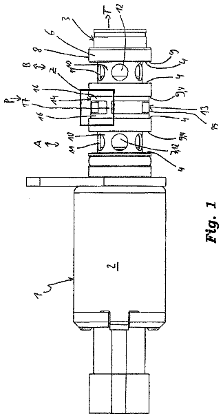
A valve timing control apparatus includes a linear solenoid having a coil, a casing, a needle, a pair of cylindrical stators and a cylindrical spacer.
US 8,534,265 B2 · Assignee: Hitachi Automotive Systems, Ltd. · Inventors: Saruwatari; Masayuki
Sheet 1 of 5 from the published document. All sheets in the USPTO PDF
The present invention relates to a fuel supply control apparatus and a fuel supply control method for controlling an electric fuel pump, in an internal combustion engine provided with the electric fuel pump for pumping fuel to a fuel injection valve and a pressure regulator for regulating fuel pressure at set pressure. When a learning condition of a drive voltage for the electric fuel pump is established, the drive voltage is temporarily reduced and a change amount .DELTA.AF of an air-fuel ratio at the time is detected. Then, if the change amount .DELTA.AF is within a first threshold .DELTA.AF1, the drive voltage is reduced, whereas, if the change amount .DELTA.AF is greater than a second threshold .DELTA.AF2 which is equal to or greater than the first threshold .DELTA.AF1, the drive voltage is increased.
Japanese Laid-open (Kokai) Patent Application Publication No. 9-126027 discloses an apparatus is provided with a sensor for detecting a flow amount of fuel to be returned to a fuel tank via a pressure regulator, the apparatus controls a drive current for a fuel pump based on the fuel flow amount detected by the sensor. According to the apparatus as described above, an excessive fuel amount to be returned to the fuel tank via the pressure regulator can be reduced. However, the apparatus provided with the sensor for detecting the flow amount has a problem in high cost performance since the sensor is disposed. Furthermore, the flow amount detected by the sensor pulsates, and thus, there is a problem in that the excessive fuel amount is hard to be controlled with high precision.
1 of 5 drawing sheets so far from the published document, cropped to the drawing. Every sheet is in the USPTO PDF.
What the patent claimed, word for word. All of it is now free to use.
The present invention relates to a fuel supply control apparatus for an internal combustion engine and a fuel supply control method thereof, and, in particular, to a fuel supply control apparatus and a fuel supply control method for controlling an electric fuel pump, in an internal combustion engine which is provided with the electric fuel pump for pumping fuel to a fuel injection valve and a pressure regulator for regulating fuel pressure at set pressure.
Japanese Laid-open (Kokai) Patent Application Publication No. 9-126027 discloses an apparatus is provided with a sensor for detecting a flow amount of fuel to be returned to a fuel tank via a pressure regulator, the apparatus controls a drive current for a fuel pump based on the fuel flow amount detected by the sensor.
According to the apparatus as described above, an excessive fuel amount to be returned to the fuel tank via the pressure regulator can be reduced.
However, the apparatus provided with the sensor for detecting the flow amount has a problem in high cost performance since the sensor is disposed. Furthermore, the flow amount detected by the sensor pulsates, and thus, there is a problem in that the excessive fuel amount is hard to be controlled with high precision.
Therefore, in view of the above problems, the present invention has an object to provide a fuel supply control apparatus for an internal combustion engine and a fuel supply control method thereof, capable of reducing an excessive fuel flow amount with high precision at a low cost.
In order to achieve the above-mentioned object, a fuel supply control apparatus according to the present invention includes: an electric power reducing unit which temporarily reduces driving electric power for an electric fuel pump; a pressure estimating unit which estimates a change amount of fuel pressure for when the driving electric power is temporarily reduced; and an electric power correcting unit which corrects the driving electric power based on the change amount of the fuel pressure.
Furthermore, in order to achieve the above-mentioned object, a fuel supply control method according to the present invention, temporarily reduces driving electric power for an electric fuel pump; estimates a change amount of fuel pressure for when the driving electric power is temporarily reduced; and corrects the driving electric power based on the change amount.
The other objects and features of this invention will become understood from the following description with reference to the accompanying drawings.
FIG. 1 is a view illustrating an internal combustion engine in an embodiment of the present invention;
FIG. 2 is a flowchart illustrating a setting process of a drive voltage in the embodiment of the present invention;
FIG. 3 is a flowchart illustrating a learning process of the drive voltage in the embodiment of the present invention;
FIG. 4 is a flowchart illustrating a setting process of a target drive current in the embodiment of the present invention; and
FIG. 5 is a flowchart illustrating a learning process of the target drive current in the embodiment of the present invention.
FIG. 1 is a view illustrating a vehicular internal combustion engine 1 provided with a fuel supply control apparatus according to the present invention.
In FIG. 1, internal combustion engine 1 is provided with a fuel injection valve 3 in an intake passage 2, and sucks fuel injected by fuel injection valve 3 together with air into a combustion chamber 5 via an intake valve 4.
The fuel in combustion chamber 5 is ignited to be combusted by spark ignition by an ignition plug 6, and internal combustion engine 1 discharges combusted gas in combustion chamber 5 to an exhaust passage 8 via an exhaust valve 7.
Internal combustion engine 1 is provided with an electronically controlled throttle 10 which is driven to open or close by a throttle motor 9, in intake passage 2 on the upstream side of fuel injection valve 3. Electronically controlled throttle 10 regulates an intake air amount of internal combustion engine 1.
Furthermore, internal combustion engine 1 is provided with a fuel supply device which pumps fuel in a fuel tank 11 to fuel injection valve 3 by the use of a fuel pump 12.
The fuel supply device includes fuel tank 11, fuel pump 12, a mechanical pressure regulator 14, fuel gallery piping 15, fuel supply piping 16 and fuel return piping 17.
Fuel pump 12 is an electrical pump of which pump impeller is driven to rotate by the use of an electric motor.
Fuel supply piping 16 connects a discharge port of fuel pump 12 to fuel gallery piping 15. To fuel gallery piping 15, a fuel supply port of each fuel injection valve 3 is connected.
Fuel return piping 17 is branched at one end thereof from fuel supply piping 16 in fuel tank 11 and the other end thereof opens into fuel tank 11.
Pressure regulator 14 is provided with a valve body which opens or closes fuel return piping 17, and an elastic member, such as a coil spring or the like, which presses the valve body toward a valve seat on the upstream side of fuel return piping 17. Then, pressure regulator 14 is opened when fuel pressure PF in fuel supply piping 16 becomes higher than set pressure SL, to relieve the fuel in fuel supply piping 16 into fuel tank 11, while being closed when the fuel pressure PF in fuel supply piping 16 becomes lower than the set pressure SL, to maintain the fuel pressure PF in the vicinity the set pressure SL. The set pressure SL is set at 350 kPa, for example.
A FPCM (Fuel Pump Control Module) 18 controls driving electric power for electric fuel pump 12, to thereby control a discharge amount of fuel pump 12 and discharge pressure thereof. To be specific, FPCM 18 is configured for controlling a drive voltage to be applied to a direct current motor which constitutes up electrical fuel pump 12, or for controlling a drive current which flows to the direct current motor at a target drive current, so that the discharge amount of fuel pump 12 and the discharge pressure thereof are controlled by changing the drive voltage or the target drive current.
On the other hand, an ECM (Engine Control Module) 31 outputs manipulated signals to fuel injection valve 3, electronically controlled throttle 10 and the like, and also, the ECM computes an indicated value of manipulated variable of fuel pump 12 to output the indicated value to FPCM 18.
Incidentally, ECM 31 may be provided with hardware of FPCM 18 and a control function thereof.
ECM 31 receives output signals from various types of sensors which detect operating conditions of internal combustion engine 1, and computes manipulated variables of fuel injection valve 3, electronically controlled throttle 10 and the like, based on these output signals, and furthermore, computes the indicated value of the manipulated variable of fuel pump 12.
As the various types of sensors described above, there are disposed: an accelerator opening sensor 34 for detecting a stroke amount ACC of an accelerator pedal (not shown in the figure); an air flow sensor 35 for detecting an intake air flow amount QA of internal combustion engine 1; a rotation sensor 36 for detecting a rotating speed NE of internal combustion engine 1; a water temperature sensor 37 for detecting cooling water temperature TW of internal combustion engine 1; an air-fuel ratio sensor 38 for detecting an air-fuel ratio AF of internal combustion engine 1 according to oxygen concentration in the exhaust gas; and the like.
ECM 31 computes a basic injection pulse width TP of fuel injection valve 3, based on the intake air flow amount QA and the engine rotating speed NE. Furthermore, ECM 31 computes an air-fuel ratio feedback correction coefficient for approaching the air-fuel ratio detected by the air-fuel ratio sensor 38 to a target air-fuel ratio, a correction coefficient for increasing a fuel injection amount when the engine is cooled down or in a high load region and the like, and corrects the basic injection pulse width TP based on these correction coefficients, to thereby compute a final injection pulse with TI.
Then, ECM 31 outputs an injection pulse signal of the injection pulse width TI to fuel injection valve 3 at injection timing of each cylinder, to control fuel injection by fuel injection valve 3.
Fuel injection valve 3 is driven to open for a period of time corresponding to the injection pulse width TI, to inject the fuel of amount proportional to a valve opening time.
Furthermore, ECM 31 computes ignition timing based on engine operating conditions, such as, a load of internal combustion engine 1, the engine rotating speed NE and the like, to control power supply to an ignition coil (not shown in the figure) so that spark ignition by ignition plug 6 is performed at the computed ignition timing.
Moreover, ECM 31 computes target opening of electronically controlled throttle 10 based on the accelerator opening ACC and the like, to control throttle motor 9 so that opening of electronically controlled throttle 10 reaches target opening.
In the followings, computation processing of the indicated value of the drive voltage for fuel pump 12, in other words, computation processing of the manipulated variable of fuel pump 12 will be described in detail.
A flowchart of FIG. 2 illustrates a computing process of the drive voltage for fuel pump 12, which is interruptedly executed for each set time by ECM 31. The set time is about 10 ms, for example.
In step S101, a basic drive voltage VBASE is calculated according to the operating conditions of internal combustion engine 1.
Incidentally, fuel pump 12 in this embodiment has characteristics in that the discharge amount/discharge pressure thereof is increased as the drive voltage/drive current becomes higher.
ECM 31 calculates the basic drive voltage VBASE, based on the basic injection pulse width TP representing the engine load and the engine rotating speed NE. To be specific, ECM 31 calculates the basic drive voltage VBASE to have a higher value, as the engine rotating speed NE becomes higher, and also, as the engine load becomes higher.
However, the discharge amount of fuel pump 12 may be less than a design value due to characteristic variations in fuel pump 12, and accordingly, if the drive voltage is set at a value for obtaining a required discharge amount, the fuel pressure PF may become lower than the set pressure SL due to the lack of discharge amount. Then, if the fuel pressure PF is lower than the set pressure SL, the injection amount per unit valve opening time of fuel injection valve 3 is decreased, so that an air-fuel ratio of air-fuel mixture may become leaner, resulting in misfire.
Therefore, in order that, even if the discharge amount of fuel pump 12 becomes less than the design value, pressure regulator 14 relieves the fuel so that the fuel pressure PF is maintained at the set pressure SL, the basic drive voltage VBASE is set to be higher than a requisite minimum value so that the discharge amount greater than the required discharge amount can be obtained.
If the basic drive voltage VBASE is calculated in step S101, and then, in step S102, the basic drive voltage VBASE is corrected based on a first correction value VLRN and a second correction value VHOS, and a correction result is set at a final drive voltage VPUMP.
To be specific, as shown in the following formula, a value which is obtained by subtracting, from the basic drive voltage VBASE, the first correction value VLRN and further, the second correction value VHOS, is set as the final drive voltage VPUMP. VPUMP=VBASE-VLRN-VHOS
The first correction value VLRN is a learning value for decreasing as much as possible the fuel amount to be relieved by pressure regulator 14, and is updated by ECM 31 in accordance with a flowchart of FIG. 3 as described below.
That is, in a state in which pressure regulator 14 does not relieve the fuel, the fuel pressure PF is lower than the set pressure SL. However, in a state in which the fuel amount relieved by pressure regulator 14 is excessive, fuel pump 12 works more than necessary, resulting in an increase in the electric power consumption.
Therefore, the basic drive voltage VBASE is set to be higher so that, even if the discharge amount of fuel pump 12 becomes the lowest within a variation range, the fuel to be relieved by pressure regulator 14 is obtained and the fuel pressure PF can be maintained at the set pressure SL. If the fuel amount to be practically relieved is excessive, the drive voltage VPUMP is corrected to be lower based on the first correction value VLRN.
Furthermore, the second correction value VHOS is a value for temporarily changing the drive voltage VPUMP to intentionally occur a change of the air-fuel ratio, in order to judge whether or not the first correction value VLRN is a proper value.
ECM 31 transmits, to FPCM 18, a voltage indication signal indicating the drive voltage VPUMP, and FPCM 18 received the voltage indication signal determines a duty ratio according to the drive voltage VPUMP, to control ON/OFF of a switching element which turns on/off the power supply to fuel pump 12 in accordance with the duty ratio.
The flowchart of FIG. 3 shows a learning process of the drive voltage, which is interruptedly executed for each set time by ECM 31.
In step S201, it is judged whether or not a learning condition of the first correction value VLRN is established.
As the learning condition, it is judged whether or not internal combustion engine 1 is in a stationary state. To be specific, when a change amount per unit time .DELTA.ST of the accelerator opening ACC, the engine load, the engine rotating speed NE or the like, is less than a threshold SLA, it is judged that internal combustion engine 1 is in the stationary state, whereas when the change amount per unit time .DELTA.ST is greater than the threshold SLA, it is judged that internal combustion engine 1 is in a transient state.
Then, if internal combustion engine 1 is in the stationary state, it is judged that the learning condition is established, and the routine proceeds to step S202.
Incidentally, as the learning condition, it may be judged that the warm-up of internal combustion engine 1 is completed, a transmission connected to an output shaft of internal combustion engine 1 in a neutral state, an elapsed time after the operation start of internal combustion engine 1 exceeds the set time, fuel temperature is lower than upper limit temperature, an external load of an air-conditioner compressor or the like which is driven by internal combustion engine 1 is in a stable state, an operation of the external load is stopped, the engine load and the engine rotating speed are within set regions, or the like.
In step S202, the second correction value VHOS is increased in stepwise from 0V being an initial value up to a set value V1 (V1>0V), and then, is returned to 0V from the set value V1 after a lapse of a set time t1 (not shown in drawings).
That is, the second correction value VHOS is kept at the set value V1 for the set time t1 in a learning mode, while being kept at 0V in modes other than the learning mode.
If the second correction value VHOS is set at the positive value V1 greater than 0V, the drive voltage VPUMP is reduced by the second correction value VHOS, so that the discharge amount of fuel pump 12 is decreased.
Here, the set time t1 which is a period of time for temporarily reducing the drive voltage VPUMP based on the second correction value VHOS, and the set value V1 which reduces the drive voltage VPUMP, are set so that the air-fuel ratio becomes leaner as a result that the injection amount per unit time of fuel injection valve 3 is decreased by the reducing-correction of the drive voltage VPUMP, and also, the air-fuel ratio is changed at the degree detectable by air-fuel ratio sensor 38, and furthermore, are set at the degree of avoiding misfire due to over-leaning of the air-fuel ratio or a shock due to torque decrease sensed by a driver.
That is, by temporarily reducing the drive voltage VPUMP based on the second correction value VHOS, such a situation is intentionally occurred in which the discharge amount of fuel pump 12 becomes deficient, so that the fuel relief from pressure regulator 14 is stopped and the fuel pressure PF becomes lower than the set pressure SL. However, the set time t1 and the set value V1 are adjusted so that, when the drive voltage VPUMP is intentionally reduced, misfire or large torque decrease does not occur, and furthermore, the leaning of the air-fuel ratio can be detected by air-fuel ratio sensor 38.
Here, if the set time t1 and the set value V1 are less than proper values, the air-fuel ratio change at the degree detectable by air-fuel ratio sensor 38 does not occur, or it becomes hard to detect variations in the air-fuel ratio due to combustion variations among the cylinders or fuel pulsation separately from the air-fuel ratio change due to the reduction of the drive voltage. On the contrary, if the set time t1 and the set value V1 are greater than the proper values, there occurs misfire due to the over-leaning of the air-fuel ratio or a torque shock sensed by a driver.
Therefore, the set time t1 and the set value V1 are set at the degree detectable of the air-fuel ratio change while suppressing degradation in operating performance of internal combustion engine 1.
Incidentally, a period of time during which the drive voltage VPUMP is reduced by the set value V1 may be set as a period of time until an integrated value of engine rotating numbers and an integrated value of intake air amount exceed thresholds, and furthermore, the set value V1 and the period of time during which the drive voltage VPUMP is temporarily reduced based on the set value V1 may be variably set according to the operating conditions, such as the engine load, the engine rotating speed and the like.
If the drive voltage VPUMP is temporarily reduced based on the second correction value VHOS in step S202, and then in step S203, it is judged whether or not a change amount .DELTA.AF of the air-fuel ratio due to the reduction of the drive voltage VPUMP is within a first threshold .DELTA.AF1.
Here, when the discharge amount of fuel pump 12 is decreased due to the reduction of the drive voltage VPUMP, so that supply pressure of the fuel to fuel injection valve 3 becomes lower than the set pressure SL of pressure regulator 14, the fuel amount injected per unit time by fuel injection valve 3 is decreased, so that the air-fuel ratio becomes leaner, and therefore, the change amount .DELTA.AF of the air-fuel ratio indicates a lean change amount of the air-fuel ratio due to the decrease of the fuel pressure PF associated with the reduction of the drive voltage VPUMP.
That is, the decrease of the fuel pressure PF associated with the reduction of the drive voltage VPUMP is estimated based on the lean change amount of the air-fuel ratio.
However, there is a delay until air-fuel ratio sensor 38 detects the air-fuel ratio change which occurs as a result that the drive voltage VPUMP is reduced based on the second correction value VHOS. Therefore, a period of time in which the delay is predicted from correction timing of the pump drive voltage VPUMP is set as a sampling period for the air-fuel ratio detected by air-fuel ratio sensor 38. Then, during the sampling period, the change amount .DELTA.AF between a mean air-fuel ratio for when the drive voltage VPUMP is not corrected based on the second correction value VHOS, in other words, for when the second correction value VHOS=0V, and the air-fuel ratio detected by air-fuel ratio sensor 38, is detected for each sampling cycle of an output from air-fuel ratio sensor 38.
Then, a maximum value among the change amounts .DELTA.AF detected during the sampling period, that is, the change amount .DELTA.AF for when the air-fuel ratio is changed to the most leaning side during the sampling period, is detected as the change amount .DELTA.AF of the air-fuel ratio as a result that the drive voltage VPUMP is reduced based on the second correction value VHOS. The change amount .DELTA.AF of the air-fuel ratio is calculated as an absolute value.
Incidentally, it is possible to detect the air-fuel ratio in a state in which the air-fuel ratio is stable on the lean side during the sampling period or the change amount .DELTA.AF of the air-fuel ratio based on the mean air-fuel ratio in this stable state, and if such a configuration is applied, it is possible to suppress an adverse effect, such as the air-fuel ratio variations, overshooting to the leaner side or the like, to thereby detect the air-fuel ratio change amount .DELTA.AF with high precision.
The case in which the change amount .DELTA.AF of the air-fuel ratio is within the first threshold .DELTA.AF1 means the case in which, even if the drive voltage VPUMP is reduced based on the second correction value VHOS, the decrease of the discharge amount due to the reduction of the drive voltage VPUMP does not cause the decrease of relief amount of the fuel from pressure regulator 14 or the large decrease of the fuel pressure PF.
That is, in a state in which pressure regulator 14 relieves the excessive fuel to fuel tank 11, the discharge amount of fuel pump 12 is greater than the consumed fuel amount in internal combustion engine 1 at the time, and even if the discharge amount is decreased by the excessive fuel, the fuel supply pressure to fuel injection valve 3 can be maintained, and accordingly, the fuel pressure is decreasingly changed by the decreased discharge amount which is over the excessive fuel, so that the air-fuel ratio becomes leaner.
Accordingly, in the case in which, even if the drive voltage VPUMP is reduced based the second correction value VHOS, the air-fuel ratio change matched with the voltage reduction does not occur, it is possible to estimate that the too much excessive fuel is obtained in a state in which the drive voltage VPUMP is not reduced based on the second correction value VHOS.
However, if the fuel amount to be relieved by pressure regulator 14 is too small, there is a possibility that the fuel pressure PF becomes temporarily lower than the set pressure SL due to pulsation associated with the injection operation, and therefore, the excessive fuel amount, which can maintain the fuel pressure even if the pulsation associated with the injection operation occurs, is determined as an allowable minimum amount (allowable minimum amount>0), and the first threshold .DELTA.AF1 is set so that the excessive fuel of allowable minimum amount cab be secured.
In other words, if the change amount .DELTA.AF of the air-fuel ratio is within the first threshold .DELTA.AF1, it is possible to estimate that the excessive fuel is in the too much excessive state in which the excessive fuel is over the allowable minimum amount.
Therefore, in step S203, if it is judged that the change amount .DELTA.AF of the air-fuel ratio is within the first threshold .DELTA.AF1, the routine proceeds to step S204, in which the previous first correction value VLRN is increased by a correction value X (VHOS.ltoreq.X), and the first correction value VLRN after increased is stored.
If a lean change of the air-fuel ratio occurred due to the temporary reduction of the drive voltage VPUMP is sufficiently small, it is judged that the excessive fuel of allowable minimum amount can be ensured even if the pump drive voltage is reduced by at least the correction value X, and the first correction value VLRN is increased by the correction value X while the drive voltage VPUMP being reduced by the correction value X, so that the discharge amount of fuel pump 12 and further the excessive fuel to be relieved by pressure regulator 14 are decreased.
That is, the basic pump drive voltage VBASE is set to be higher so that the excessive fuel becomes at least the allowable minimum amount even if the discharge amount relative to the drive voltage VPUMP becomes a minimum value due to various variation factors.
Therefore, the excessive discharge amount due to the basic pump drive voltage VBASE is decreased based on the first correction value VLRN, and if the discharge amount of fuel pump 12 causes the too much excessive fuel, the first correction value VLRN is increased while the drive voltage VPUMP being reduced.
Accordingly, it is possible to learn the drive voltage at which the excessive fuel becomes a lower limit amount in fuel pump 12, in other words, a further lower drive voltage within a drive voltage range in which the required injection amount can be ensured, and it is possible to suppress that the too much drive voltage causing the too much excessive fuel amount is applied to fuel pump 12, to reduce the power consumption of fuel pump 12, to thereby improve the fuel consumption performance of internal combustion engine 1.
Incidentally, an initial value of the first correction value VLRN is 0V, and may be a uniform correction value to be used for all operating regions. Or, the first correction value VLRN may be stored in updatable as an individual value for each of a plurality of operating regions which are separated from one another based on the engine load and the engine rotating speed for example, so that the value stored in response to the corresponding operating region at the time can be updated, and also, the drive voltage VPUMP can be calculated based on the value stored in response to the corresponding operating region at the time.
On the other hand, in step S203, if it is judged that the change amount .DELTA.AF of the air-fuel ratio is not within the first threshold .DELTA.AF1, in other words, if the air-fuel ratio becomes leaner for over a predetermined value due to the temporary reduction of the drive voltage VPUMP, it is judged that the excessive fuel becomes less than the allowable minimum amount if the pump drive voltage VPUMP is further reduced by the correction value X, and the routine proceeds to step S205.
That is, it is judged that, as the leaning of air-fuel ratio due to the temporary reduction of the drive voltage VPUMP is larger, the excessive fuel amount is small in the state in which the drive voltage VPUMP is not reduced based on the second correction value VHOS, whereas, if the change amount .DELTA.AF of the air-fuel ratio is greater than the first threshold .DELTA.AF1, the excessive fuel amount is in the vicinity of the allowable minimum amount, and accordingly, it is not possible to perform at least the further decrease of the excessive fuel amount.
In step S205, it is judged whether or not the change amount .DELTA.AF of the air-fuel ratio, which occurred when the drive voltage VPUMP was temporarily reduced, is equal to or greater than a second threshold .DELTA.AF2 (.DELTA.AF2.gtoreq..DELTA.AF1).
If the change amount .DELTA.AF of the air-fuel ratio is less than the second threshold .DELTA.AF2, it is judged that, although there is no room for further reducing the pump drive voltage VPUMP, the excessive fuel of allowable minimum amount is obtained, and this routine is terminated directly, so that the value of the first correction value VLRN is maintained as the previous value.
On the other hand, if the change amount .DELTA.AF of the air-fuel ratio, which occurred when the drive voltage VPUMP was temporarily reduced, is equal to or greater than the second threshold .DELTA.AF2, it is judged that the excessive fuel in the state in which the drive voltage VPUMP is not reduced based on the second correction value VHOS, is less than the allowable minimum amount, and the routine proceeds to step S206.
In step S206, the previous first correction value VLRN is decreased by the correction value X, and the first correction value VLRN after decreased is stored.
That is, if the change amount .DELTA.AF of the air-fuel ratio, which occurs when the drive voltage VPUMP is temporarily reduced, is equal to or greater than the second threshold .DELTA.AF2, it is possible to estimate that the drive voltage VPUMP is excessively reduced based on the first correction value VLRN, and also, the excessive fuel amount is less than the allowable minimum amount. Therefore, by decreasing the first correction value VLRN while increasing the drive voltage VPUMP and furthermore the discharge amount of fuel pump 12, the excessive fuel over the allowable fuel amount is obtained.
Then, as a result that the first correction value VLRN is decreased in step S206, if the change amount .DELTA.AF of the air-fuel ratio, which occurs when the drive voltage VPUMP is temporarily reduced, becomes less than the second threshold .DELTA.AF2, it is estimated that at least the excessive fuel of allowable minimum amount is obtained, and the decrease of the first correction value VLRN is stopped.
Accordingly, if the pump discharge amount obtained relative to the drive voltage VPUMP is decreased due to deterioration with time of fuel pump 12 or the like, the drive voltage VPUMP is increased, to thereby obtain the excessive amount of allowable minimum amount.
Incidentally, a decreasing-correction range of the first correction value VLRN in step S206, in other words, an increasing-correction range of the drive voltage VPUMP, may be same as an increasing-correction range of the first correction value VLRN in step S204, in other words, a reducing-correction range of the drive voltage VPUMP. Or, the decreasing-correction range of the first correction value VLRN in step S206 may be set to be wider than the increasing-correction range of the first correction value VLRN in step S204.
This is because, in the case in which the too much excessive fuel is obtained due to the excess of the drive voltage VPUMP, although the electric power consumption is increased, the fuel pressure PF can be regulated at the set pressure SL and the air-fuel ratio controllability can be maintained, whereas, in the state in which the drive voltage VPUMP is too low, since the fuel pressure PF for fuel injection valve 3 is lower than the set pressure SL and there is a possibility of misfire due to the leaning of the air-fuel ratio, it is desired that the fuel pressure is restored promptly.
Furthermore, in the decreasing-correction of the first correction value VLRN in step S206 and in the increasing-correction of the first correction value VLRN in step S204, if the correction is consecutively performed for increasing (or decreasing), it is possible to make the correction range of the first correction value VLRN smaller in stepwise, and thus, the drive voltage VPUMP can be further brought closer to the requisite minimum value.
Moreover, in the above embodiment, the change of the air-fuel ratio due to the temporary reduction of the drive voltage VPUMP is detected as a change of oxygen concentration in the exhaust gas by air-fuel ratio sensor 38, however, in the case in which a sensor for detecting an inner pressure of the cylinder is provided for misfire detection, a change of combustion pressure due to the leaning of the air-fuel ratio may be detected as a value equivalent to the air-fuel ratio change.
Still further, in a system in which the drive current for fuel pump 12 is controlled, it is possible to perform learning in that a target drive current is increased or reduced based on the air-fuel ratio change for when the drive current is temporarily reduced, and thus, the discharge pressure of fuel pump 12 is varied. A second embodiment in such a configuration will be described hereunder in accordance with flowcharts of FIG. 4 and FIG. 5.
FIG. 4 is the flowchart illustrating a computing process of a target pump drive current, which is interruptedly executed for each set time by ECM 31.
In step S401, a basic drive current ABASE is calculated according to the operating conditions of internal combustion engine 1.
The basic drive current ABASE is set as a value at which the excessive fuel is relieved by pressure regulator 14 even if there are the characteristic variations in fuel pump 12. Furthermore, since the variations in fuel pressure are increased on the high rotation/high load side, as illustrated in the figure, the basic drive current ABASE may be set to be higher on the high rotation/high load side.
After the basic pump drive current ABASE is calculated in step S401, and then, in step S402, the basic pump drive current ABASE is corrected based on a first correction value ALRN and a second correction value AHOS, and a correction result is set as a final target drive current APUMP.
To be specific, as shown in the following formula, a value obtained by subtracting, from the basic drive current ABASE, the first correction value ALRN and further, the second correction value AHOS, is set as the final target drive current APUMP. APUMP=ABASE-ALRN-AHOS
The first correction value ALRN is a learning value for decreasing as much as possible the too much excessive fuel due to the basic drive current ABASE, and ECM 31 performs the learning in accordance with the flowchart of FIG. 5.
Furthermore, the second correction value AHOS is a value for temporarily changing the target drive current APUMP to intentionally change the air-fuel ratio, in order to judge whether or not the first correction value ALRN is a proper value.
ECM 31 transmits, to FPCM 18, a signal indicating the target drive current APUMP, and FPCM 18 received the signal indicating the target drive current APUMP controls ON/OFF of a switching element which turns on/off the drive current to fuel pump 12, based on a duty ratio according to the target drive current APUMP.
FIG. 5 is the flowchart illustrating a learning process of the target drive current, which is interruptedly executed for each set time by ECM 31.
In step S501, similarly to step S201, it is judged whether or not a learning condition is established, and if it is judged that the learning condition is established, the routine proceeds to step S502.
In step S502, the second correction value AHOS is increased in stepwise from 0 being an initial value up to a set value A1 (not shown in drawings; A1>0A), and then, is returned in stepwise to 0 from the set value A1 after the lapse of the set time t1.
That is, the second correction value AHOS is maintained at the set value A1 for the set time t1 when the learning condition is established, while being maintained at 0 at other times.
As described in the above, the second correction value AHOS is the value to be subtracted from the basic drive current ABASE, and if the value of the second correction value AHOS is set at a positive value A1 greater than 0A, the target drive current APUMP is reduced by the second correction value AHOS and the discharge pressure of fuel pump 12 is decreased.
Here, similar to the set time t1 and the set value V1 for the second correction value VHOS, the set time t1 and the set value A1 for the second correction value AHOS are set at the degree detectable of the air-fuel ratio change while suppressing the degradation in operating performance of internal combustion engine 1.
Here, a period of time during which the target drive current APUMP is reduced by the set value A1 may be a period of time until the integrated value of engine rotating numbers and the integrated value of intake air amounts exceed the thresholds, instead of defining the period by the time, and furthermore, the set value A1 and the period of time during which the set value A1 is applied may be variably set according to the operating conditions, such as the engine load, the engine rotating speed and the like.
If the target drive current APUMP is temporarily reduced based on the second correction value AHOS in step S502, then in step S503, it is judged whether or not the change amount .DELTA.AF of the air-fuel ratio due to the reduction of the target drive current APUMP is within a third threshold .DELTA.AF3.
Here, when the discharge amount of fuel pump 12 is decreased due to the reduction of the target drive current APUMP, so that the supply pressure PF becomes lower than the set pressure SL of pressure regulator 14, the fuel amount injected per unit time by fuel injection valve 3 is decreased, so that the air-fuel ratio becomes leaner, and therefore, the change amount .DELTA.AF of the air-fuel ratio indicates a leaning range of the air-fuel ratio associated with the reducing-correction of the target drive current APUMP.
Here, there is a delay until air-fuel ratio sensor 38 detects the air-fuel ratio change which occurs as a result that the target drive current APUMP is corrected based on the second correction value AHOS. Therefore, a period of time in which the delay is predicted is set as a sampling period for the air-fuel ratio detected by air-fuel ratio sensor 38. Then, a difference between a mean air-fuel ratio for when the correction based on the second correction value AHOS is not performed, and the air-fuel ratio on the most leaning side during the sampling period, may be detected as the air-fuel ratio change amount as a result that the drive current is corrected based on the second correction value AHOS.
Furthermore, the case in which the change amount .DELTA.AF of the air-fuel ratio is within the third threshold .DELTA.AF3 means a state in which the too much excessive fuel is obtained in the state in which the correction based on the second correction value AHOS is not performed, and even if the target drive current APUMP is reducing-corrected based on the second correction value AHOS, the fuel pressure is not decreased by the value corresponding to the second correction value AHOS.
Therefore, when it is judged in step S503 that the change amount .DELTA.AF of the air-fuel ratio is within the third threshold .DELTA.AF3, and then, the routine proceeds to step S504 in which the previous first correction value ALRN is increased by a correction value Y (AHOS.ltoreq.Y), and the first correction value ALRN after increased is stored.
If the leaning change of the air-fuel ratio due to the temporary reduction of the target drive current APUMP is sufficiently small, it is judged that the excessive fuel of allowable minimum amount can be ensured even if the target drive current APUMP is reduced by at least the correction value Y, and then, the first correction value ALRN is increased by the correction value Y, while the target drive current APUMP being reduced by the correction value Y.
That is, the basic drive current ABASE is set to be higher so that the set pressure SL can be obtained as the fuel pressure PF, in other words, the excessive fuel is relieved from pressure regulator 14, even if the discharge pressure relative to the drive current becomes a minimum value due to various variation factors.
Therefore, an excessive amount of the basic drive current ABASE is decreased based on the first correction value ALRN, and if the too much excessive fuel is obtained, the target drive current APUMP is reduced in stepwise by the correction of the first correction value ALRN.
Incidentally, an initial value of the first correction value ALRN is 0, and may be a uniform correction value to be used for all operating regions. Or, the first correction value ALRN may be stored in updatable as an individual value for each of the plurality of operating regions which are separated based on the engine load and the engine rotating speed for example, so that the value stored in response to the corresponding operating region at the time can be updated, and the target drive current APUMP can be calculated based on the value stored in response to the corresponding operating region at the time.
The description continues in the full USPTO document.
About 6,788 words. The USPTO PDF has it with every drawing.
Fees are due 3.5, 7.5 and 11.5 years after grant. This patent expired on September 17, 2025, so the fee marked "not paid" was the one that went unpaid.
FUEL SUPPLY CONTROL APPARATUS FOR INTERNAL COMBUSTION ENGINE AND FUEL SUPPLY CONTROL METHOD THEREOF
Filed Sep 2010 · published Sep 2011Fuel supply control apparatus for internal combustion engine and fuel supply control method thereof
Filed Sep 2010 · granted Sep 2013Earlier publications, parents and continuations. None of them can still be enforced, or this patent would not be listed.
Prior art cited by the examiner or applicant. Useful when you check your own idea for novelty.
Everything on this page comes from the documents linked above.