Technical field
The present invention relates to a printing plate cylinder to which a sleeve-shaped printing plate is detachably attached, a printing apparatus including the same, and a method for producing a printing plate cylinder. The present invention also relates to a printing plate cylinder including a cooling mechanism for keeping good ink viscosity at the time of printing, its cooling member, and a printing apparatus for a can. The present invention also relates to a printing plate cylinder which is supported by a rotary shaft of a printing apparatus and on a cylindrical surface of which a printing plate having an image pattern is mounted and used, and an offset printing apparatus including the printing plate cylinder.
The present application claims priority on Japanese Patent Application No. 2008-047583, filed Feb. 28, 2008, Japanese Patent Application No. 2008-088332, filed Mar. 28, 2008, Japanese Patent Application No. 2008-300831, filed Nov. 26, 2008, and Japanese Patent Application No. 2009-021936, filed Feb. 2, 2009, the contents of which are incorporated herein by reference.
Background art
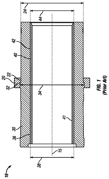
A sleeve-shaped printing plate to be used for various kinds of printing, as in, for example, Patent Document 1, is fitted through a printing plate cylinder, and thereby fixed so as to come into close contact with the outer circumferential surface of the printing plate cylinder. A conventional printing plate cylinder is formed substantially in a cylindrical shape which has a hollow air chamber, and is constructed to form an air supply hole which penetrates into the air chamber from an axial end surface thereof, and an air outlet hole which penetrates into the air chamber from an outer circumferential surface thereof.
In this printing plate cylinder, when air is introduced into the air chamber from the air supply hole to raise the pressure of the air chamber in a state where the printing plate is fixed to the outer circumferential surface of the printing plate cylinder so as to block the air outlet, high-pressure air is blown off through the air outlet with this pressure rise. Accordingly, when the printing plate is attached to and detached from the printing plate cylinder, since the printing plate can be inflated radially outward by the high-pressure air which is blown off through the air outlet, the printing plate can be easily attached and detached.
Additionally, the following one is conventionally known as a common problem related to the printing quality in a printing apparatus under operation. That is, in the cylindrical printing plate cylinder having the printing plate, to which a printing design (image portion) is given, on the outer circumferential surface thereof, at the time of printing, the surface temperature of the printing plate is gradually raised due to frictional heat with a blanket in contact with the printing plate or the conduction of heat from a driving shaft side which supports a rotating shaft portion, and accordingly ink temperature rises, and ink viscosity decreases. As a result, ink spread, color tones or the like vary, and printing quality is reduced. Additionally, in a waterless planographic plate, it is known that such a temperature rise of the printing plate cylinder promotes deterioration of the printing plate.
In order to prevent such a phenomenon, for example, in a printing apparatus disclosed in Patent Document 2, cold air is forcibly applied to a shaft portion of a rotating printing plate cylinder, and the temperature of the printing plate cylinder and the printing plate is lowered for cooling.
Meanwhile, in recent years, there is known a CTS (Computer To plate on Sleeve) technique of using a cylindrical sleeve member on the outer circumferential surface of which a printing plate is installed, directly laser-machining the printing plate to form an image portion, and then allowing attachment and detachment of each sleeve member to/from the printing plate cylinder. According to this CTS technique, positioning of the printing plate can be easily performed with high accuracy, and the operation process for forming an image portion on the printing plate and replacement (attachment and detachment) of the printing plate can be simply and easily performed. Thus, productivity is remarkably increased.
Generally, a two-piece can to be used as a container, such as for soft drinks, is composed of a can lid, and a can barrel which is a cylindrical body. The can barrel is subjected to DI (deep-drawing, ironing) work and cleaning, and then printing is performed on the outer surface of the can barrel. When a cylindrical object, such as the can barrel, is printed, for example, the offset printing apparatus using offset printing as shown in Patent Document 1 is used.
Such an offset printing apparatus includes a plurality of printing plate cylinders which forms a substantially columnar shape or a substantially cylindrical shape, and has a printing plate composed of a relief printing plate or the like on the cylindrical surface, and a blanket cylinder which rotates in synchronization with these printing plate cylinders, and has a blanket made of rubber disposed on the outer circumferential surface, and the printing plates of the printing plate cylinders and the blanket of the blanket cylinder come into contact with each other. Ink is applied to the printing plate of each printing plate cylinder, this ink is transferred to the blanket, and this blanket comes into contact with the outer circumferential surface of the can barrel so that printing is performed on the outer circumferential surface of the can barrel.
In such a printing plate cylinder, since it is necessary to arrange the printing plate with high accuracy on the cylindrical surface, the stability of the external diameter is required. Additionally, since the printing plate cylinder is attached to and detached from a rotary shaft of the printing apparatus, the accuracy of the shape of the portion in which the rotary shaft is fitted is required. For this reason, generally, the conventional printing plate cylinder has relatively high rigidity, and is constituted of carbon steel having excellent workability.
[Patent Document 1] Japanese Patent Unexamined Publication No. 2007-44987
[Patent Document 2] Japanese Patent Unexamined Publication No. 2002-347214
Disclosure of invention
Problems to be Solved by the Invention
Since the above conventional printing plate cylinder is constructed to have a large air chamber, there is a problem in that the weight of the printing plate cylinder becomes heavy.
Additionally, since heat radiation at the time of printing is low in this printing plate cylinder, the viscosity of ink is not stabilized, and it becomes difficult to achieve a constant printing state. As a result, there is also a problem in that unevenness occurs in printing.
Moreover, after the printing plate is inflated by high-pressure air and mounted on the printing plate cylinder, there is also a problem in which dew is apt to be formed in the air chamber or the air outlet hole of the printing plate cylinder. That is, in a state wherein the printing plate is inflated by high-pressure air and mounted on the printing plate cylinder, the air chamber is held at high pressure. However, when piping for air supply is removed from the air supply hole after the mounting of the printing plate, the pressure in the air chamber drops rapidly, and consequently, dew is formed in the air chamber or the air outlet hole of the printing plate cylinder. Here, in a case where the printing plate cylinder is made of a raw material which may rust like iron, formation of dew becomes a factor of generation of rust. When rust is generated in the air chamber or the air outlet hole, there is a possibility that the attachability and the detachability of the printing plate to and from the printing plate cylinder may deteriorate.
Additionally, in the printing apparatus of Patent Document 2, since it is necessary to provide a forced air-cooling device which generates cold air for cooling the printing plate cylinder, or to provide an air-cooling duct for blowing off the cold air generated by the forced air-cooling device to the shaft portion of the printing plate cylinder, there is a problem in that the configuration of the apparatus becomes complicated, and the facility cost, the operation cost, and the maintenance cost are increased.
Meanwhile, in the printing plate cylinder made of carbon steel, rust may be generated at the time of use. Particularly, since it becomes impossible to arrange the printing plate with high accuracy when rust is generated on the cylindrical surface, in the conventional printing plate cylinder made of carbon steel, a plating treatment is performed on the cylindrical surface.
For this reason, especially, in a large-sized printing plate cylinder, it is required that rust is not generated even if the plating treatment is omitted.
Additionally, the weight of a printing plate cylinder made of carbon steel becomes comparatively heavy. For this reason, in a case where printing plate cylinders are frequently replaced, or in a case where the rigidity of a rotary shaft of a printing apparatus is low, the weight reduction of the printing plate cylinder is required.
Additionally, since carbon steel has good heat conduction, the heat generated from a driving unit of a printing apparatus is transmitted through a rotary shaft, and the temperature of the cylindrical surface of a printing plate cylinder is apt to rise. Then, there is a possibility that the temperature of the printing plate disposed on the cylindrical surface may also rise, the viscosity of ink adhering to this printing plate may change in a printing process, and the printing quality may deteriorate significantly. For this reason, especially in a case where there is the need of performing a prolonged printing job, the printing plate cylinder which can suppress transmission of heat is required.
As such, characteristics required for the printing plate cylinder are various according to printing conditions (printing states), and these requirements cannot be satisfied in the conventional printing plate cylinder made of carbon steel.
The present invention was made in view of such a situation, and an object thereof is to provide a printing plate cylinder, a printing apparatus including the same, and a method for producing the printing plate cylinder, which can reduce weight and improve heat radiation, and can also suppress generation of rust, a printing apparatus including the printing plate cylinder, and a method for producing the printing plate cylinder.
Additionally, another object of the present invention is to provide a printing plate cylinder, its cooling member, and a printing apparatus for a can which can cool the printing plate cylinder with a simple configuration, suppress the rise of the ink temperature of the printing plate to stabilize ink viscosity, and secure accuracy of ink spread, color tones, etc. even at the time of continuous operation.
Moreover, still another object of the present invention is to provide a printing plate cylinder and an offset printing apparatus including this printing plate cylinder, capable of satisfying various characteristics which are required according to printing conditions (printing states).
Means for Solving the Problems
In order to solve the above problems, the printing plate cylinder related to the present invention is a printing plate cylinder detachably mounted with a sleeve printing plate which forms a cylindrical shape. The printing plate cylinder includes a shaft portion rotatable about a central axis, a tubular portion formed cylindrically, arranged coaxially with the shaft portion, and arranged at a distance from an outer circumferential surface of the shaft portion, and a rib fixed integrally to the outer circumferential surface of the shaft portion and an inner circumferential surface of the tubular portion and connecting the shaft portion and the tubular portion. The tubular portion is formed with an air outlet hole opened to an outer circumferential surface of the tubular portion, the rib is formed with an air supply passage which communicates with the air outlet hole, and the sleeve printing plate is mounted with an increased diameter by blown off air from the air outlet hole through the air supply passage.
In addition, an air supply port for introducing air into the air supply passage formed in the rib can be formed at arbitrary positions, such as positions where the sleeve printing plate is not disposed among the outer surface of the rib, the outer circumferential surface and axial end surface of the shaft portion, the inner circumferential surface of the tubular portion, and the outer circumferential surface of the tubular portion.
In the printing plate cylinder of this configuration, since the sleeve printing plate inflates radially outward when the sleeve printing plate is mounted, and high-pressure air is blown off through the air outlet hole, the sleeve printing plate can be smoothly mounted. In addition, in this configuration, even if high-pressure air is blown off through the air outlet hole when the sleeve printing plate is removed, it is similarly possible to smoothly remove the sleeve printing plate.
According to this printing plate cylinder, since the shaft portion and the tubular portion are connected together by the rib, it is possible to make the diameter of the shaft portion small or to make the thickness of the tubular portion thin, and it is possible to easily reduce the weight of the printing plate cylinder.
Additionally, since the gap region between the shaft portion and the tubular portion can be opened to the outside from both axial ends of the printing plate cylinder by connecting the shaft portion and the tubular portion together by the rib, it is possible to efficiently cool the printing plate cylinder, for example, by make cooling air flow to this gap region at the time of printing. That is, the heat radiation at the time of printing can be improved, and the viscosity of ink can be stabilized to prevent occurrence of printing unevenness.
Moreover, since a large air chamber is not provided in the printing plate cylinder unlike the conventional printing plate cylinder, and the air supply passage with a small volume is simply formed, even if the pressure of the air supply passage drops sharply, formation of dew can be suppressed to the minimum. As a result, generation of rust on the printing plate cylinder can be suppressed, and deterioration of the attachability and detachability of the sleeve printing plate to the printing plate cylinder can be prevented.
In the above printing plate cylinder, preferably, the tubular portion includes an inside tubular portion formed integrally with the rib, and an outside tubular portion mounted on an outer circumferential surface of the inside tubular portion.
Additionally, in the above printing plate cylinder, preferably, the air outlet hole is formed so as to penetrate in the thickness direction of the outside tubular portion, a plurality of the air outlet holes is arrayed in the circumferential direction of the outside tubular portion, and at least one of the outer circumferential surface of the inside tubular portion and the inner circumferential surface of the outside tubular portion is formed with an air circulation groove which is formed so as to extend in the circumferential direction and communicates with the air supply passage and the plurality of air outlet holes.
According to the printing plate cylinder of this configuration, the high-pressure air introduced into the air supply passage can be evenly delivered in the circumferential direction by the air circulation groove. Therefore, even if the number of the air supply passages is fewer than the number of the air outlet holes, it is possible to uniformly blow off the high-pressure air introduced into the air supply passage through each air outlet hole.
Additionally, in the printing plate cylinder of this configuration, it is possible to easily form the air supply passage, the air circulation groove, and the air outlet hole. Therefore, the air supply channel through which air is guided from the air supply port to the air outlet hole can be simply formed. For example, the air supply passage can be easily formed simply by forming an axial hole which extends in the axial direction from the axial end surface of the rib, and forming a radial hole which extends radially inward from the outer circumferential surface of the inside tubular portion so as to communicate with the axial hole.
Moreover, in the above printing plate cylinder, preferably, the plurality of air outlet holes and the air circulation groove may be plurally arranged even in the axis direction.
When the sleeve printing plate is attached to and detached from the printing plate cylinder, the sleeve printing plate is moved in the axial direction with respect to the printing plate cylinder. However, by adopting the above-described configuration, high-pressure air can be blown off through a plurality of axial places of the outer circumferential surface of the outside tubular portion. Therefore, in the process of detaching and attaching the sleeve printing plate, the inflation state of the sleeve printing plate by the high-pressure air can be maintained long, and it is possible to smoothly attach and detach the sleeve printing plate.
Additionally, in the above printing plate cylinder, preferably, a plurality of the ribs and a plurality of the air supply passages formed in the ribs are formed so as to shift from each other in the circumferential direction, and the respective air supply passages communicate individually with the plurality of air circulation grooves arrayed in the direction of the axis.
In this configuration, supply of high-pressure air can be individually controlled with respect to the plurality of air outlet holes formed in a plurality of axial places. Therefore, it is possible to blow off high-pressure air only through the air outlet hole covered with the sleeve printing plate. Accordingly, it is possible to prevent high-pressure air from being blown off wastefully to efficiently attach and detach the sleeve printing plate.
Moreover, in the above printing plate cylinder, the inside tubular portion and the outside tubular portion may be formed from different materials.
For example, the inside tubular portion may be formed from a material having good workability, and the outside tubular portion may be formed from a material having rigidity and corrosion resistance. As a specific example of this combination, the inside tubular portion may be formed from carbon steel for a mechanical structure, and the outside tubular portion may be formed from stainless steel. In this case, forming work of the aforementioned air circulation groove or air outlet hole can be easily performed on the inside tubular portion or the rib formed integrally with the inside tubular portion. Additionally, the outside tubular portion can be prevented from deforming at the time of printing, or from corroding due to ink or the like.
Additionally, the printing apparatus of the present invention is constructed using the above printing plate cylinder.
According to this printing apparatus, the weight of the printing apparatus can be reduced by providing the lightweight printing plate cylinder. Additionally, since occurrence of printing unevenness can be suppressed at the time of printing, the yield of cans can be improved.
Moreover, since generation of rust in the printing plate cylinder can also be suppressed, it is possible to use the same printing plate cylinder over a long period of time without replacement, and it is consequently possible to reduce the running cost of the printing apparatus.
Also, the method for producing a printing plate cylinder related to the present invention is a method for producing the printing plate cylinder constructed so that the tubular portion includes the inside tubular portion and the outside tubular portion. The method includes hollowing a columnar member used as a material of the shaft portion, the rib, and the inside tubular portion in the direction of the axis, thereby producing a core member in which the shaft portion, the rib, and the inside tubular portion are integrally shaped, and then mounting the core member in the outside tubular portion.
According to the method for producing a printing plate cylinder of the present invention, it is possible to obtain a core member in which the shaft portion, the rib, and the inside tubular portion which extends in the axial direction of the columnar member are integrally shaped. By mounting the core member in the outside tubular portion after the completion of production of the core member, it is possible to prevent deviation from occurring in the external diameter of the inside tubular portion with respect to the internal diameter of the outside tubular portion. That is, it is possible to shape the inside tubular portion with high accuracy.
In the method for producing a printing plate cylinder, in a case where shaping of the shaft portion, the rib, and the inside tubular portion is performed by machining, such as wire cutting work or cutting work, the shapes of the shaft portion, the rib, and the inside tubular portion can be finished with higher accuracy.
Additionally, the present invention suggests the following means in order to achieve the above objects. That is, the present invention provides a printing plate cylinder including a shaft portion rotating about a central axis, and a tubular portion spaced apart from the outside of the shaft portion to form a region and disposed coaxially and integrally with the shaft portion. Fins are disposed to generate an air stream in the region with the rotation.
According to the printing plate cylinder related to the present invention, fins generate an air stream in the region between the shaft portion and the tubular portion with this rotation of the printing plate cylinder at the time of printing. Therefore, the printing plate cylinder is cooled by this air stream, and temperature can be prevented from rising excessively even at the time of continuous operation. Accordingly, the temperature rise of ink to be applied to the outer circumferential surface of the printing plate cylinder is suppressed, ink viscosity is stabilized, and good accuracy of ink spread, color tones or the like is maintained.
Additionally, in the printing plate cylinder of the present invention, the fins may extend to incline with respect to the central axis.
According to the printing plate cylinder of the present invention, the fins extend to incline so as to be twisted with respect to the central axis of the printing plate cylinder, and the direction of the central axis and the extension direction of the fins are set so as not to be parallel to each other. The shape of the fins is formed, for example, spirally about the central axis. By such fins, when the printing plate cylinder has rotated at the time of printing, the fins are adapted to reliably generate an air stream in the direction of the central axis, and the generated air stream exchanges heat with the surfaces or the like which forms the region, thereby suppressing the temperature rise of the printing plate cylinder.
Additionally, in the printing plate cylinder of the present invention, a cooling member attachable to and detachable from the end in the direction of the central axis may be provided, and the cooling member may include the fins, and rotate integrally with the shaft portion to generate an air stream in the region.
Additionally, the present invention provides a cooling member to be mounted on a printing plate cylinder including a shaft portion rotating about a central axis, and a tubular portion spaced apart from the outside of the shaft portion to form a region and disposed coaxially and integrally with the shaft portion. The cooling member includes fins which generate an air stream in the region with the rotation, and is made attachable to and detachable from the end of the printing plate cylinder in the direction of the central axis.
According to the printing plate cylinder and its cooling member of the present invention, fins are formed on the cooling member attachable to and detachable from the end in the direction of the central axis. Thus, when the printing plate cylinder has rotated, the shaft portion and the cooling member rotate integrally, and the fins of the cooling member generate an air stream in the region between the shaft portion and the tubular portion. Accordingly, for example, in a case where a printing apparatus is provided with a plurality of printing plate cylinders, the number or shape of the fins of the cooling member can be set in accordance with a desired cooling temperature of each printing plate cylinder, or the cooling member can be easily installed by post-installation, and it is possible to cope with various demands of cooling of the printing plate cylinders flexibly.
Additionally, in the printing plate cylinder of the present invention, the fins may be erected with at least one of the outer circumferential surface of the shaft portion or the inner circumferential surface of the tubular portion on base ends.
According to the printing plate cylinder of the present invention, since an air stream is generated as the erected fins reliably catch and sweep away the air in the region between the shaft portion and the tubular portion by rotation at the time of printing, the printing plate cylinder is effectively cooled.
Additionally, in the printing plate cylinder of the present invention, ribs may be provided to connect the outer circumferential surface of the shaft portion and the inner circumferential surface of the tubular portion together, and the ribs may be the fins.
According to the printing plate cylinder of the present invention, the ribs which connect the outer circumferential surface of the shaft portion and the inner circumferential surface of the tubular portion are used as the fins for cooling. Thus, the effect of cooling the printing plate cylinder with a simple configuration is obtained without increasing the number of components compared to the conventional technique.
Additionally, in the printing plate cylinder of the present invention, a driving shaft which is arranged coaxially with the shaft portion to rotatably support the shaft portion may be provided, and the air stream may be set so as to flow from the tip side of the driving shaft in the direction of the central axis towards the base end side of the driving shaft.
According to the printing plate cylinder of the present invention, the air stream to be generated by the fins is set so as to flow from the tip side of the driving shaft in the direction of the central axis towards the base end side of the driving shaft. Thus, cooled ambient air is easily drawn into the region, and the conduction of heat to the printing plate cylinder from the driving shaft which generates heat at the time of operation is suppressed, thereby improving cooling efficiency.
Additionally, the present invention is a printing apparatus performing printing on a can using a printing plate cylinder, and the aforementioned printing plate cylinder is used.
According to the printing apparatus for a can related to the present invention, it is possible to improve the accuracy and productivity of printing to cope with the various demands of printing of cans flexibly.
Moreover, in order to solve the aforementioned problems, the printing plate cylinder related to the present invention is a printing plate cylinder having a cylindrical surface extending along an axis and mounted with a printing plate having an image pattern on the cylindrical surface. The printing plate cylinder includes a core member which has a fitting hole into which a rotary shaft of a printing apparatus is fitted, and a sleeve member arranged on the outer circumferential side of the core member and having the cylindrical surface. The core member and the sleeve member are made of different materials.
According to the printing plate cylinder of this configuration, the core member into which the rotary shaft is fitted, and the sleeve member on which the printing plate is mounted are separately formed, and the core member and the sleeve member are made of mutually different materials. Thus, it is possible to appropriately select the materials of the core member and the sleeve member according to required characteristics. For example, by forming the core member from a material having good workability, it is possible to shape a fitting hole with high dimensional accuracy, and attachment and detachment of the printing plate cylinder and the rotary shaft can be smoothly performed. Additionally, by forming the sleeve member in which the printing plate is disposed from a material in which rust is hardly generated, it becomes unnecessary to perform plating treatment. Additionally, by forming either the core member or the sleeve member from a material whose heat conductivity is lower than carbon steel, the heat generated from a driving unit of a printing apparatus is hardly transferred to the printing plate, and it is possible to stably perform printing for a long period of time.
Thus, it is possible to construct a suitable printing plate cylinder having the required characteristics.
Here, one or more interlayers may be formed between the sleeve member and the core member.
In this case, by selecting the material of the interlayer provided between the sleeve member and the core member, it is possible to add further characteristics to the printing plate cylinder. For example, by forming the interlayer from a material whose heat conductivity is lower than carbon steel, conduction of heat generated from a driving unit of a printing apparatus can be suppressed, without changing the material of the core member or the sleeve member.
Additionally, the core member may be made of carbon steel, and the sleeve member may be made of stainless steel.
In this case, the core member is made of carbon steel having excellent workability. Thus, the fitting hole into which the rotary shaft is fitted can be shaped with high dimensional accuracy, and it is possible to smoothly perform attachment and detachment of the printing plate cylinder. Additionally, since the sleeve member is made of stainless steel, generation of rust can be suppressed, and it is not necessary to perform plating treatment on the cylindrical surface. Hence, the lifespan of the printing plate cylinder can be extended.
Additionally, the core member may be made of stainless steel, and the sleeve member may be made of a resin material.
In this case, since the core member is made of stainless steel, it is possible to suppress generation of rust in the core member. Additionally, since the sleeve member is made of a resin material, it is possible to reduce the weight of the printing plate cylinder, and generation of rust on the cylindrical surface can be suppressed. Moreover, since the resin material has low heat conductivity, conduction of heat generated from a driving unit of a printing apparatus can be suppressed.
Additionally, the core member may be made of a resin material, and the sleeve member may be made of stainless steel.
In this case, since the core member is made of a resin material, it is possible to reduce the weight of the printing plate cylinder. Additionally, conduction of heat generated from a driving unit of a printing apparatus can be suppressed.
Additionally, since the sleeve member is made of stainless steel, it is possible to suppress generation of rust, and plating treatment becomes unnecessary. Moreover, since the sleeve member made of stainless steel having high rigidity is arranged on the outer circumferential side, even if the core member made of a resin material tends to deform due to thermal expansion, the deformation is suppressed by the sleeve member. Thus, the shape stability of the printing plate cylinder can be secured.
Additionally, the core member may be made of carbon steel, the sleeve member may be made of stainless steel, and an interlayer made of a resin material may be formed between the core member and the sleeve member.
In this case, since the core member is made of carbon steel having good workability, the fitting hole into which the rotary shaft is fitted can be shaped with high dimensional accuracy. Additionally, since the sleeve member is made of stainless steel, generation of rust can be suppressed. Moreover, since the interlayer made of a resin material is formed between the core member and the sleeve member, conduction of heat generated from a driving unit of a printing apparatus can be suppressed.
The offset printing apparatus related to the present invention includes the aforementioned printing plate cylinder, and a rotary shaft which rotatably supports the printing plate cylinder about the axis.
According to the offset printing apparatus of this configuration, printing can be stably performed by using the printing plate cylinder with characteristics according to printing conditions (printing states).
Effects of the Invention
According to the present invention, the weight of the printing plate cylinder can be reduced, and occurrence of printing unevenness at the time of printing can be prevented. Additionally, formation of dew can be suppressed to the minimum, and deterioration of attachability and detachability of the sleeve printing plate to the printing plate cylinder can also be prevented.
Additionally, according to the printing plate cylinder, its cooling member, and the printing apparatus for a can related to the present invention, the printing plate cylinder can be cooled with a simple configuration, the rise of the ink temperature of the printing plate can be suppressed to stabilize ink viscosity, and accuracy of ink spread, color tones or the like can be secured even at the time of continuous operation. Accordingly, it is possible to improve the accuracy and productivity of printing to cope with various demands of printing flexibly.
Moreover, according to the present invention, it is possible to provide the printing plate cylinder and the offset printing apparatus including this printing plate cylinder, capable of satisfying various characteristics which are required according to printing conditions (printing states).
Brief description of drawings
FIG. 1 is a schematic perspective view showing a printing plate cylinder related to a first embodiment of the present invention.
FIG. 2 is a schematic side sectional view of the printing plate cylinder of FIG. 1.
FIG. 3 is a schematic perspective view showing a state where the printing plate cylinder of FIG. 1 is separated into a core member and an outside tubular portion.
FIG. 4 is a schematic side sectional view showing a state where a shaft portion and a sleeve printing plate are fixed to the printing plate cylinder of FIG. 1.
FIG. 5 is a schematic view showing a printing apparatus for a can using the printing plate cylinder of FIG. 1.
FIG. 6 is a schematic perspective view showing a state where a printing plate cylinder related to a second embodiment of the present invention is fixed to the shaft portion.
FIG. 7 is a schematic side sectional view of the printing plate cylinder of FIG. 6.
FIG. 8 is a schematic perspective view showing a state where a printing plate cylinder related to a third embodiment of the present invention is fixed to the shaft portion.
FIG. 9 is a schematic side sectional view of the printing plate cylinder of FIG. 8.
FIG. 10 is a partial transmissive perspective view showing the outline of a printing plate cylinder related to other embodiment of the present invention.
FIG. 11 is a partial transmissive perspective view showing the schematic configuration of a printing plate cylinder related to a fourth embodiment of the present invention.
FIG. 12 is a schematic side view showing the printing plate cylinder related to the fourth embodiment of the present invention.
FIG. 13 is a schematic view showing a printing apparatus for a can using the printing plate cylinder of the fourth embodiment of the present invention.
FIG. 14 is a partial transmissive perspective view showing the schematic configuration of a printing plate cylinder related to a fifth embodiment of the present invention.
FIG. 15 is a schematic side view showing the printing plate cylinder related to the fifth embodiment of the present invention.
FIG. 16 is a partial transmissive perspective view showing the schematic configuration of a printing plate cylinder related to a sixth embodiment of the present invention.
FIG. 17 is a schematic side view showing the printing plate cylinder related to the sixth embodiment of the present invention.
FIG. 18 is a partial transmissive perspective view showing the schematic configuration of a printing plate cylinder related to a seventh embodiment of the present invention.
FIG. 19 is a schematic perspective view showing a printing plate cylinder related to an eighth embodiment of the present invention.
FIG. 20 is a schematic side sectional view of the printing plate cylinder of FIG. 19.
FIG. 21 is a schematic perspective view showing a state where the printing plate cylinder of FIG. 19 is separated into a core member and a sleeve member.
FIG. 22 is a schematic side sectional view showing a state where a rotary shaft and a sleeve printing plate are fixed to the printing plate cylinder of FIG. 19.
FIG. 23 is a perspective view of a sleeve printing plate which is mounted on the printing plate cylinder shown in FIG. 19.
FIG. 24 is a view when the sleeve printing plate of FIG. 23 is observed from the direction of an axis.
FIG. 25 is a schematic view showing a printing apparatus for a can using the printing plate cylinder of FIG. 19.
FIG. 26 is a schematic perspective view showing a printing plate cylinder related to a ninth embodiment of the present invention.
FIG. 27 is a schematic perspective view showing a printing plate cylinder related to a tenth embodiment of the present invention.
FIG. 28 is a schematic perspective view showing a printing plate cylinder related to an eleventh embodiment of the present invention.
Explanation of reference
TABLE-US-00001 1, 71, 81: PRINTING PLATE CYLINDER 3: SHAFT PORTION 3a: OUTER CIRCUMFERENTIAL SURFACE 5: TUBULAR PORTION 5a: OUTER CIRCUMFERENTIAL SURFACE 5b: INNER CIRCUMFERENTIAL SURFACE 7: RIB 15: INSIDE TUBULAR PORTION 15a: OUTER CIRCUMFERENTIAL SURFACE 17: OUTSIDE TUBULAR PORTION 17b: INNER CIRCUMFERENTIAL SURFACE 31, 73, 83A, 83B: AIR SUPPLY CHANNEL 33, 75A TO 75C, 85A, 85B: AIR CIRCULATION GROOVE 35, 77, 87, 88: AIR SUPPLY PASSAGE 37, 79, 89: AIR OUTLET HOLE O: CENTRAL AXIS P: SLEEVE PRINTING PLATE 1001: SHAFT PORTION 1002: TUBULAR PORTION 1003, 1023: RIB 1004, 1014, 1024, 1034: FIN 1010, 1020, 1030, 1040: PRINTING PLATE CYLINDER 1011: DRIVING SHAFT 1041: COOLING MEMBER 1050: PRINTING APPARATUS FOR CAN C: CENTRAL AXIS S: REGION BETWEEN SHAFT PORTION AND TUBULAR PORTION 2006: ROTARY SHAFT 2040, 2140, 2240, 2340: PRINTING PLATE CYLINDER 2050, 2150, 2250, 2350: CORE MEMBER 2051, 2151, 2251, 2351: FITTING HOLE 2060, 2160, 2260, 2360: SLEEVE MEMBER 2000A:
Offset printing apparatus
Best mode for carrying out the invention
The description continues in the full USPTO document.
 Lapsed, fee not paid2 drawings