 Lapsed, fee not paid2 drawings
Software & Apps · US 8,533,776 B2
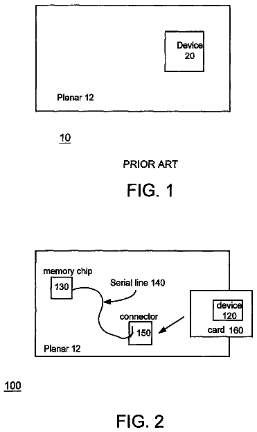
Method and system for binding a device to a planar
A method and system for binding a device to a planar is disclosed.
US 8,533,813 B2 · Assignee: Oki Data Corporation · Inventors: Machiyama; Kenichi
Sheet 1 of 14 from the published document. All sheets in the USPTO PDF
An image processing apparatus capable of managing easily secret information even with detachably attaching an external memorizing device, includes an ID (plug and play ID) retrieving unit for retrieving ID from the connected memory, a user information storing unit for storing user information, an active memory information storing unit for storing the retrieved ID with corresponding to the respective users, a memory use judging unit for judging as to whether the memory is usable based on the ID retrieved from the connected memory and on the ID stored in the active memory information storing unit, and a data writing controlling unit for writing data to the memory judged as usable.
An art has been proposed in which a recording medium detachably attached to a scanner body is connected to directly write to the recording medium the image data obtained through reading an original document (see, e.g., Japanese Unexamined Patent Publication No. 2002-10025). In such a prior art, a scanner is disclosed in which a memorizing medium such as a memory card or a magneto-optical recording medium is directly connected to a scanner body to write the read image data into the recording medium. With this art, this scanner can execute reading operation without connecting to any information processing apparatus such as a personal computer. Not only scanners as described above, but also image processing apparatuses such as, e.g., multi-function peripherals, or MFPs allowing the external memorizing device including a memorizing medium to be detachably attached, are widely used these days
1 of 14 drawing sheets so far from the published document, cropped to the drawing. Every sheet is in the USPTO PDF.
What the patent claimed, word for word. All of it is now free to use.
This invention relates to an image processing apparatus detachably attaching an external memorizing device and to an image processing system having such an image processing apparatus.
An art has been proposed in which a recording medium detachably attached to a scanner body is connected to directly write to the recording medium the image data obtained through reading an original document (see, e.g., Japanese Unexamined Patent Publication No. 2002-10025). In such a prior art, a scanner is disclosed in which a memorizing medium such as a memory card or a magneto-optical recording medium is directly connected to a scanner body to write the read image data into the recording medium. With this art, this scanner can execute reading operation without connecting to any information processing apparatus such as a personal computer.
Not only scanners as described above, but also image processing apparatuses such as, e.g., multi-function peripherals, or MFPs allowing the external memorizing device including a memorizing medium to be detachably attached, are widely used these days. With such image processing apparatuses, any user can advantageously save the electronic data easily in the external memorizing device, but there raises a problem from a view to information management because secret information stored in the image processing apparatus can be easily taken out.
It is therefore an object to provide an image processing apparatus capable of easily managing secret information even though allowing an external memorizing device to be detachably attached, and also to provide an image processing system having such an image processing apparatus.
According to the invention, foregoing objects are accomplished with an image processing apparatus to which an external memorizing device for making data writable thereto is detachably attached, the image processing apparatus comprising: a connection unit for connecting the external memorizing device in which specific memorizing device identification information is stored; an identification information retrieving unit for retrieving the memorizing device identification information from the external memorizing device connected to the connection unit; a user information storing unit for storing user information relating to a user; a memorizing device usage allowance information storing unit for beforehand storing, in a manner corresponding to the user information, the memorizing device identification information retrieved by the identification information retrieving unit; a memorizing device usage judgment unit for judging as to whether the external memorizing device is used, based on the memorizing device identification information retrieved out of the external memorizing device by the identification information retrieving unit and on the memorizing device identification information stored in the memorizing device usage allowance information storing unit corresponding to the user information beforehand, where the external memorizing device is connected to the connection unit; and a data writing controlling unit for writing data to the external memorizing device where the memorizing device usage judgment unit judges as that the external memorizing device connected to the connection unit is usable.
In another aspect of the invention, an image processing system has an external memorizing device for making data writable thereto and an image processing apparatus detachably attaching the external memory device. The external memorizing device includes: an identification information storing unit for storing specific memorizing device identification information; and a data storing unit for storing data received from the image processing apparatus. The image processing apparatus includes: a connection unit for connecting the external memorizing device; an identification information retrieving unit for retrieving the memorizing device identification information from the external memorizing device connected to the connection unit; a user information storing unit for storing user information relating to a user; a memorizing device usage allowance information storing unit for beforehand storing, in a manner corresponding to the user information, the memorizing device identification information retrieved by the identification information retrieving unit; a memorizing device usage judgment unit forjudging as to whether the external memorizing device is used, based on the memorizing device identification information retrieved out of the external memorizing device by the identification information retrieving unit and on the memorizing device identification information stored in the memorizing device usage allowance information storing unit corresponding to the user information beforehand, where the external memorizing device is connected to the connection unit; and a data writing controlling unit for writing data to the external memorizing device where the memorizing device usage judgment unit judges as that the external memorizing device connected to the connection unit is usable.
With the image processing apparatus and the image processing system, the memorizing device usage allowance information storing unit stores the user information and the memorizing device identification information of the external memorizing device usable by the user corresponding to the user information, and where the external memorizing device is connected to the connection unit, a judgment is made as to whether the external memorizing device is usable based on the memorizing device identification information retrieved from the external memorizing device and the memorizing information identification information stored in the memorizing device usage allowance information storing unit, and the image processing apparatus restricts data writing to the external memorizing device. That is, with the image processing apparatus and the image processing system according to the invention, the user can limit the usable external memorizing device.
According to the invention, because the user can limit usable external memorizing device, the management of the secret information can be performed easily upon creating a situation that the secret information cannot be taken out freely, so that information management can surely be made.
This invention may take physical form in certain parts and arrangements of parts, a preferred embodiment and method of which will be described in detail in this specification and illustrated in the accompanying drawings which form a part hereof, and wherein:
FIG. 1 is a block diagram illustrating a structure of an image processing apparatus according to a first embodiment of the invention;
FIG. 2 is a front view showing a structure of a manipulation controlling unit incorporated in a multifunction peripheral shown in FIG. 1;
FIG. 3 is a memory table illustrating examples of user information stored in a user information storing unit incorporated in the multifunction peripheral shown in FIG. 1 and active memory information stored in an active memory information storing unit;
FIG. 4 is a flowchart illustrating a series of recording processings when user information and connectable USB memory are recorded in the multifunction peripheral in the image processing system according to the first embodiment of the invention;
FIG. 5 is a diagram showing a screen of user information registration displayed on a displaying unit arranged at the multifunction peripheral shown in FIG. 1;
FIG. 6 is a diagram showing a screen of function use limitation information setting displayed on a displaying unit arranged at the multifunction peripheral shown in FIG. 1;
FIG. 7 is a diagram showing a screen of USB memory registration displayed on a displaying unit arranged at the multifunction peripheral shown in FIG. 1;
FIG. 8 is a diagram showing a command sequence performed between the multifunction peripheral shown in FIG. 1 and the USB memory when the multifunction peripheral retrieves PnPID of the USB memory to store PnPID in active memory information storing unit;
FIG. 9 is a diagram showing a data structure of a device scripter stored in the USB memory;
FIG. 10 is a flowchart showing a series of image data writing processing at a time when image data read with a reading unit are written to the USB memory in the image processing system shown as the first embodiment of the invention;
FIG. 11 is a diagram showing a specific example of a login screen displayed at a displaying unit incorporated in the multifunction peripheral shown in FIG. 1;
FIG. 12 is a block diagram showing a structure of an image processing system according to a second embodiment of the invention;
FIG. 13 is a flowchart showing a series of registration processings at a time when user identification in the user information and use limitation information on multifunction peripheral's functions are registered in the multifunction peripheral in the image processing system according to the second embodiment of the invention;
FIG. 14 is a flowchart showing a series of registration processings at a time when user password in the user information and a connectable USB memory are registered in the multifunction peripheral in the image processing system according to the second embodiment of the invention;
FIG. 15 is a diagram showing a specific example of a user information registration screen displayed at a displaying unit incorporated in the multifunction peripheral shown in FIG. 12;
FIG. 16 is a diagram showing a specific example of a user identification entry screen displayed at a displaying unit incorporated in the multifunction peripheral shown in FIG. 12;
FIG. 17 is a diagram showing a specific example of a user password notice screen displayed at a displaying unit incorporated in the multifunction peripheral shown in FIG. 12;
FIG. 18 is a flowchart illustrating a series of processings when the USB memory is connected to a personal computer in the image processing system according to the second embodiment of the invention; and
FIG. 19 is a diagram showing a specific example of a login screen displayed at a displaying unit incorporated in the multifunction peripheral shown in FIG. 12.
In the following embodiments, a multifunction peripheral serving as an image processing apparatus having multiple image processing functions such as copying function, facsimile function, and scanner function, and an image processing system having such a multifunction peripheral are described. The multifunction peripheral particularly can detachably attach a USB (Universal Serial Bus) memory as an external memorizing device; a user can limit a usable USB memory or USB memories; and each user can limit usable functions.
First Embodiment
As shown in FIG. 1, the multifunction peripheral 100 has: a manipulation controlling unit 101 serving as a controller for receiving user's manipulations and performing various controls according to the manipulations and as a user information entry unit; a reading unit for reading original documents; an image processing unit 103 for processing image data read with the reading unit 102; an image buffer 104 for temporarily storing image data processed by the image processing unit 103; a USB interface unit 105 serving as a connection unit for making communications with a USB memory 200 connected to the multifunction peripheral 100; a user information storing unit 106 for storing a variety of information regarding the user; a user judging unit 107 for judging functions usable by the login user; a plug and play ID or PnPID retrieving unit 108 serving as an identification information retrieving unit for retrieving "plug and play ID (referred to as "PnPID") of the USB memory 200 connected to the multifunction peripheral 100; an active memory information storing unit 109 as memorizing device usage allowance information storing unit for storing active memory information showing activeness with respect to each user on the USB memory 200 connected to the multifunction peripheral 100; a memory use judging unit 110 serving as a memorizing device use judging unit for judging as to whether data writing usage is allowed with respect to the USB memory 200 connected to the multifunction peripheral 100; and a data writing controlling unit 111 for controlling writing of image data to the USB memory 200.
The manipulation controlling unit 101 receives entire manipulations in which a user makes entry of manipulations to the multifunction peripheral 100, and performs various controls according to the manipulations. More specifically, the manipulation controlling unit 101, as shown in, e.g., FIG. 2, includes a displaying unit 112 for displaying such as setting items and status information of the multifunction peripheral 100, a ten key 113 for entering letters and numbers, a cursor key 114 for moving a cursor displayed on the displaying unit 112 during, e.g., manipulations for various settings, an enter key 115 for entering items indicated by the cursor displayed on the displaying unit 1112 and for entering inputted contents, a plurality of mode switching buttons 116 for switching operation modes of the multifunction peripheral 100, a start button 117 for beginning executions of respective functions owned by the multifunction peripheral 100, and a stop button 118 for stopping processing in operation.
The manipulation controlling unit 101 thus structured displays a prescribed scanner function screen on the displaying unit 112 when receiving manipulation for designating reading original documents, such as, e.g., in a case that a user pushed down a scanning button among the mode switching buttons 116. Necessary information such as resolution is entered with the ten keys 113 to the manipulation controlling unit 101, and the manipulation controlling unit 101 controls the reading unit 102 to make reading operation of the original documents according to pushing down manipulation of the start button 117. The manipulation controlling unit 101 displays a prescribed setting screen at the displaying unit 112 in a case where the user pushes down the setting button among the mode switching buttons 116. The manipulation controlling unit 101 here displays a prescribed registration screen at the displaying unit 112 in a case where an item indicating registration manipulation of the user information is selected among the setting items displayed at the setting screen and where the enter key is pushed down. The manipulation controlling unit 101 stores the entered user information in the user information storing unit 106 according to the pushing down manipulation of the enter key 115 where the user information is inputted using the ten keys or the like. With those operations, the user information is surely registered in the multifunction peripheral 100. The manipulation controlling unit 101 displays a prescribed login screen 112 at the displaying unit 112 in a case where an item indicating a login manipulation is selected among the setting items displayed on the setting screen according to the manipulation of the cursor key 14 and where the enter key is pushed down. The manipulation controlling unit 101 supplies the received login information to the user judging unit 107 upon inputting the login information in use of the ten keys 113 and pushing down the enter key 115, thereby rendering the user judge the functions usable for the user.
The reading unit 102 reads original documents set to an original document setting table of a flat bed scanner type not shown and an automatic document feeder or ADF with a prescribed resolution to produce electronic image data. The reading unit 102 supplies the produced image data to the image processing unit 103.
The image processing unit 103 performs various image processings on the image data read and produced with the reading unit 102. The image processing unit 103, for example, performs image processing to convert image data read with the reading unit 102 into data in a format writable in the USB memory 200. The image processing unit 103 temporarily stores in the image buffer 104 the processed image data.
The image buffer 104 is made of, e.g., random access memories, and memorizes temporarily image data produced through image processing with the image processing unit 103. It is to be noted that the image buffer 104 is for temporarily storing image data and enough with volatile memories. The image data stored in the image buffer 104 are read out with the data reading controlling unit 111.
The USB interface unit 105 is constituted of ports detachably attaching the USB memory 200 and makes communications with the USB memory 200 connected to the multifunction peripheral 100. More specifically, the USB interface unit 105 transmits the image data to the USB memory 200 upon supplied with image data stored in the image buffer 104 via the data writing controlling unit 111. The USB interface unit 105 receives PnPID in the USB memory 200 connected to the multifunction peripheral 100 according to a request of the PnPID retrieving unit 108 and supplies the received PnPID to the PnPID retrieving unit 108.
The user information storing unit 106 is made of non-volatile memories such as, e.g., flash memories and EEPROM (Electronically Erasable and Programmable Read Only Memory) and stores user information supplied from the manipulation controlling unit 101. It is to be noted that the user information includes, as shown in, e.g., an upper table in FIG. 3, user number assigned sequentially to each user who is registered as a user using the multifunction peripheral 100, and user ID and password for distinguishing respective users, and further includes usage limitation information on respective functions that the user can use among functions given to the multifunction peripheral 100. In the upper table in FIG. 3, the items for copy, scanner, and facsimile are usage limitation information; an item having its flag of "1" indicates that the function is usable; an item having its flag of "0" indicates that the function is not usable. For example, in the upper stage in FIG. 3, a user registered with the user number "0001" is indicated as he can use the copying function and the scanner function but cannot use the facsimile function. The user information stored in the user information storing unit 107 thus formed are read out with the user judging unit 107 and the memory use judging unit 110.
The user judging unit 107 judges authority of login operation for each user based on the login information supplied from the manipulation controlling unit 101 and the user information read out of the user information storing unit 106, and also judges functions usable by the user among the functions given to the multifunction peripheral 100. The user judging unit 107 supplies user judgment information indicating the judgment result to the memory use judging unit 110.
The PnPID retrieving unit 108 retrieves PnPID of the USB memory 200 via the USB interface unit 105 at a time when the USB memory 200 is connected to the multifunction peripheral 100. The PnPID is described as follows. The plug and play devices have to store identification information assigned individually to distinct each device as one particular set in order to read in appropriate driver software upon recognition of the connecting host apparatus as one particular set. The identification information is PnPID. The PnPID is assigned to each device by the manufacturer of the device, and is stored in the device hardware. More specifically, the PnPID is constituted of a vender ID made of two bites, a product ID made of two bites, and a device specific ID made of two bites that can be set from 0x0000 to 0xFFFF. The vender ID is identification information indicating the device manufacturer. The product ID and the device specific ID are identification information assigned to individual product models by the device manufacturer, and the same product ID or the same device specific ID cannot be assigned to other product models made by the same device manufacturer. Accordingly, in the lower table in FIG. 3, in a case of PnPID corresponding to the user number "0000", the vender ID is hexadecimal number information of "ABCD"; the product ID is hexadecimal number information of "1111"; the device specific ID is hexadecimal number information of "00FF". The PnPID retrieving unit 108 retrieves such a PnPID according to connection of the USB memory 200 to the multifunction peripheral 100 and supplies the retrieved PnPID to the memory use judging unit 110. The PnPID retrieving unit 108 retrieves the PnPID from a new USB memory 200 and renders the active memory information storing unit 109 store the retrieved PnPID in a case when the USB memory 200 is newly registered.
The active memory information storing unit 109 is made of non-volatile memories such as e.g., flash memories or EEPROMs, and stores active memory information indicating activeness with respect to users on the USB memory 200 connected to the multifunction peripheral 100. More specifically, the active memory information is, as shown in the lower table in FIG. 3, information corresponding the user number to the PnPID of the USB memory unable by the user corresponding to the user number. It is to be noted that in the lower table in FIG. 3, the word "NULL" set forth in the item of the PnPID indicates a status that the USB memory is not registered. That is, in the lower table in FIG. 3, the USB memory that the user registered at the user number "0001" can use is not registered yet. The active memory information stored in the active memory information storing unit 109 thus formed is read out with the memory use judging unit 110.
The memory use judging unit 110 reads out the user information corresponding to the user who made login, based on the user judgment information supplied from the user judging unit 107, and reads out the active memory information corresponding to the user number contained in the read-out user information from the active memory information storing unit 109. More specifically, the memory use judging unit 110, as shown in FIG. 3, links the user information read out of the user information storing unit 106 with the active memory information read out of the active memory information storing unit 109 using the user number as a key, thereby reading out the active memory information corresponding to the login user from the active memory information storing unit 109. The memory use judging unit 110 compares the PnPID of the read-out active memory information with the PnPID of the USB memory 200 connected to the multifunction peripheral 100 supplied from the PnPID retrieving unit 108, and judges as to whether writing use of the data is allowed for the USB memory 200 based on the judgment result. The memory use judging unit 110 supplies the memory use judgment information showing the judgment result to the data writing controlling unit 111.
The data writing controlling unit 111 controls writing of the image data to the USB memory 200 based on the memory use judgment information supplied from the memory use judging unit 110. More specifically, the data writing controlling unit 111 transfers image data read out of the image buffer 104 to the USB interface unit 105 in a case where the memory use judgment information supplied from the memory use judging unit 110 includes contents allowing writing use of the data, thereby writing the data in the USB memory 200. On the other hand, the data writing controlling unit 111 controls not to read out the image data from the image buffer 104 in a case where the memory use judgment information supplied from the memory use judging unit 110 includes contents not allowing writing use of the data.
The multifunction peripheral 100 thus structured makes registrations of the connectable USB memories 200 with respect to the users, also makes registrations of usable functions with respect to the users, and makes writings of the image data to the USB memory 200 where it is judged as that the use is matching with the registered contents.
To the contrary, the USB memory 200 connected to the multifunction peripheral 100 thus formed includes, as shown in FIG. 1, a USB interface unit 201 for communications with the multifunction peripheral 100, a PnPID storing unit 202 serving as identification information storing unit storing PnPID of the USB memory 200, and a data storing unit 203 for storing image data.
The USB interface unit 201 is structured of such as a plug detachably attached to the USB interface unit 105 of the multifunction peripheral 100 to be connected, and communicates with the multifunction peripheral 100. More specifically, the USB interface unit 201 reads out the own PnPID stored in the PnPID storing unit 202 where the multifunction peripheral 200 to be connected provides a retrieving request on the PnPID, and transmits the PnPID to the multifunction peripheral 100. The USB interface unit 201 receives the image data transmitted from the multifunction peripheral 100 and stores the received image data in the data storing unit 203.
The PnPID storing unit 202 is made of non-volatile memories such as, e.g., flash memories or EEPROMs and stores the PnPID of the USB memory 200. The PnPID stored in the PnPID storing unit 202 is read out by the USB interface unit 201 when the multifunction peripheral 100 to be connected makes a retrieving request.
The data storing unit 203 is made of non-volatile memories such as, e.g., flash memories or EEPROMs and constitutes a main memorizing unit of the USB memory 200. More specifically, the data storing unit 203 stores image data received from the multifunction peripheral 100 via the USB interface unit 201.
The USB memory 200 thus formed is connected to the multifunction peripheral 100 upon registration to the multifunction peripheral 100 with respect to the usable users and is utilized as a saving location of the image data.
In the multifunction peripheral 100 to which such a USB memory 200 is connectable, it is required to make registrations of the user information and the connectable USB memories 200 beforehand. More specifically, the multifunction peripheral 100 executes a series of processings as shown in FIG. 4 as this registration processing. It is to be noted that the following description is for a case in which an apparatus manager of the multifunction peripheral 100 makes a registration of the user information and the USB memory and in which he allows the USB memory 200 registered at the multifunction peripheral 100 to be used by respective users upon providing the USB memory 200.
In the multifunction peripheral 100, the registration manipulation of the user information and the USB memory 200 is done by the manipulation controlling unit 101. The manipulation controlling unit 101 first of all displays a prescribed user information registration screen at the displaying unit 112 at step S101 as shown in FIG. 4. The user information registration screen is constituted to allow the user ID and the user password to enter as shown in, e.g., FIG. 5. With the manipulation controlling unit 101, the apparatus manager enters the user ID and the user password using the ten keys 113 (see FIG. 2) or the like in entry boxes of the user information registration screen thus formed, and accepts the entered user ID and user password to be set at steps S102 and S103 according to pushing down of the enter key 115. In FIG. 5, a situation in which a user having the user ID of "ab012345" makes a registration of the user ID and user password is shown.
The manipulation controlling unit 101 subsequently displays a prescribed function usage limitation information setting screen on the displaying unit 112 at step S104. The function usage limitation information setting screen is structured, as shown in, e.g., FIG. 6, to be capable of setting as to whether the usage of respective functions given to the multifunction peripheral 100 is active or inactive. With the manipulation controlling unit 101, the apparatus manager selectively designates either active or inactive operation using the cursor keys 114 or the like on the function usage limitation information setting screen thus formed, and sets allowance or not allowance of usage of the respective functions at step S105 according to pushing down of the enter key 115. In FIG. 6, a situation that the copying function, the facsimile function, and the scanner function given to the multifunction peripheral 100 are made usable is shown.
The manipulation controlling unit 101 makes the user ID, the user password, and the usage limitation information correspond to the prescribed user number at step S106 after completion of setting of the user ID, the user password, and the usage limitation information, and makes registration upon storing the information as the user information in the user information storing unit 106. For example, the manipulation controlling unit 101 renders, as shown in the upper table in FIG. 3, the user information on the user having the user ID of #ab012345'' stored in the user information storing unit 106 upon corresponded to the user number of "0000".
Upon completion of the registration of the user information in such a way, the manipulation controlling unit 101 displays a prescribed USB memory registration screen at the displaying unit 112 at step S107. The USB memory registration screen is as shown in, e.g., FIG. 7 constituted of such as a message for asking the USB memory as the registration target to connect to the multifunction peripheral 100. The manipulation controlling unit 101 at step S108 enters in a state waiting for connection of the USB memory 200 to the multifunction peripheral 100 upon displaying such a USB memory registration screen at the displaying unit 112.
The manipulation controlling unit 101 shifts the processing to step S109 in a case where it is detected that the USB memory 200 is connected to the USB interface unit 105, and makes a request to the PnPID retrieving unit 108 so as to retrieve the PnPID of the connected USB memory 200. The PnPID retrieving unit 108 according to this operation retrieves from the PnPID storing unit 202 the PnPID of the connected USB memory 200.
The PnPID retrieving unit 108 looks the active memory information storing unit 109 at step 110, and judges as to whether the retrieved PnPID is already registered or not. The manipulation controlling unit 101 at step S107 displays a USB memory registration screen showing a message or the like prompting exchange of the USB memory at the displaying unit 112 in a case where the retrieved PnPID is already registered as a result of the judgment done by the PnPID retrieving unit 108. To the contrary, the PnPID retrieving unit 108 at step S111 makes corresponding with the PnPID the user number corresponding to the user ID to be recorded and makes registration as the active memory information in a case where the retrieved PnPID is not already registered or namely where the connected USB memory 200 is a new one, and completes a series of registration processings. With this processing, as previously shown in, e.g., the lower table in FIG. 3, the USB memory 200 usable for the user having the user ID of "ab01235" is only the USB memory having the PnPID of "ABCD111100FF".
The manipulation controlling unit 101 shifts the processings to step S112 in a case where it is not detected that the USB memory 200 is connected to the USB interface unit 105, and judges as to whether the stop button 118 is pushed down by the apparatus manager. That is, the manipulation controlling unit 101 judges as to whether a manipulation to interrupt the registration of the USB memory 200 is made or not.
The manipulation controlling unit 101 repeats processings subsequent to step S108 where the stop button 118 is not pushed down. Where the stop button 118 is pushed down, the manipulation controlling unit 101 makes the user number corresponding to the user ID to be registered, corresponding to "NULL" which indicates that the USB memory is not yet registered, as in a situation of the user number of "0001" in, e.g., the lower table in FIG. 3 previously shown, thereby making registration upon stored in the active memory information storing unit 109 as the active memory information, and completing a series of registration processings.
The multifunction peripheral 100 can register the user information and the connectable USB memories 200 upon performing such a series of registration processings. It is to be noted that in the processings from step S108 to step S111 as described above, the processing in which the multifunction peripheral 100 retrieves the PnPID of the USB memory 200 and stores the PnPID in the active memory information storing unit 109 is done with a command sequence as shown in FIG. 8. A command sequence in complying with a specification of USB version 2.0 is described herein.
As shown in FIG. 8, when the USB memory 200 is connected to the multifunction peripheral 100 at step S201, the USB interface unit 105 detects the connected USB memory 200 at step S202. The USB interface unit 105 sets up a channel for communications with the detected USB memory 200 at step S203, confirms the status of the USB memory 200 at step S204, and waits for completion of initialization of the USB memory 200. It is to be noted that the confirmation of the status of the USB memory 200 is done by the USB interface unit 105 transmitting a Get_Port_Status request to the USB memory 200 and by the USB memory 200 transmitting its response to the USB interface unit 105.
The USB interface unit 105 subsequently transmits a Get_Descriptor request to the USB memory 200 to retrieve the maximum packet length of the USB memory 200 at step S205 and retrieves the device descriptor of the USB memory 200. The device descriptor is, as shown in FIG. 9, data set forth in a hierarchical way in a table format as to what specification the USB device has, and includes the vender ID constituting PnPID, the product ID and the device specific ID. Accordingly the USB memory 200 stores the device descriptor in the PnPID storing unit 202, and the USB interface unit 105 retrieves the device descriptor from the PnPID storing unit 202.
The USB interface unit 105 at step S206 transmits Set_Address request to the USB memory 200 to assign the addresses on the USB bus to the USB memory 200.
The USB interface unit 105 at step S207 transmits Get_Descriptor request to the USB memory 200 to retrieve the PnPID of the USB memory 200, thereby retrieving the device descriptor of the USB memory 200. More specifically, the USB interface unit 105 retrieves, as the PnPID, information of two bites each stored in the idVender field, the idProduct field, and the bcdDevice field as shown in FIG. 9. For example, where the PnPID of the USB memory 200 is "ABCD111100FF", the USB interface unit 105 retrieves hexadecimal number information of "ABCD" stored in the idVender field, hexadecimal number information of "1111" stored in the idProduct field, and hexadecimal number information of "00FF" stored in the bcdDevice field.
When the USB interface unit 105 retrieves the PnPID from the USB memory 200 in a way thus described, the PnPID retrieving unit 108 retrieves the PnPID transferred from the USB interface unit 105 at step S208. The PnPID retrieving unit 108 renders the active memory information storing unit 109 store the retrieved PnPID at step S209.
The multifunction peripheral 100 retrieves the PnPID from the USB memory 200 according to the command sequence and stores the PnPID in the active memory information storing unit 109.
The multifunction peripheral 100 can write to the USB memory 200 the image data read with the reading unit 102 where the user information and the connectable USB memory 200 are registered in the above described manner. More specifically, the multifunction peripheral 100 performs a series of processings as shown in FIG. 10 for image data writing processing.
First, the manipulation controlling unit 101 at step 301 displays a prescribed login screen at the displaying unit 112 as shown in FIG. 10. The login screen is structured to be able to enter the user ID and user password as shown in, e.g., FIG. 11. The manipulation controlling unit 101 accepts at step 302 the entered user ID and user password according to entries of the user ID and user password using the ten keys 113 or the like by the user into the entry box of the login screen and according to pushing down of the enter key 115. It is to be noted that in FIG. 11, it is shown that the user having the user ID of "ab012345" makes the login.
If the user judging unit 107 judges that the user who performed the login manipulation is one of the registered users, the user judging unit 107 looks up the user information storing unit 106 at step S303 to judge as to whether this user can use the scanner function. For example, the user judging unit 107, as shown previously in the upper table in FIG. 3, judges the user can use the scanner function if the user having the user ID of "ab012345" made the login, and judges the user cannot use the scanner function if the user having the user ID of "ab234567" made the login. The multifunction peripheral 100 repeats the processings from step S301 if the user is judged as cannot use the scanner function, and conversely, shifts the processings to step S304 to enter into a waiting state for connection of the USB memory 200 to the multifunction peripheral 100 if the user is judged as can use the scanner function.
If it is detected that the USB memory 200 is connected to the USB interface unit 105, the manipulation controlling unit 101 at step S305 requests to the PnPID retrieving unit 108 so as to retrieve the PnPID of the connected USB memory 200. The PnPID retrieving unit 108 according to this operation retrieves the PnPID from the PnPID storing unit 202 of the connected USB memory 200. This retrieval of the PnPID is done according to the command sequence as shown in FIG. 8 previously.
The memory use judging unit 110 looks up the active memory information storing unit 109 at step S306, compares the PnPID in the active memory information corresponding to the user number of the login user with the PnPID retrieved by the PnPID retrieving unit 108, and judges as to whether writing use of the data is allowed to the connected USB memory 200. More specifically, the memory use judging unit 110 allows writing use of the data to the USB memory 200 only where the PnPID of the active memory corresponding to the user number of the login user coincides to the PnPID retrieved by the PnPID retrieving unit 108.
If it is judged that writing use of the data to the USB memory 200 is not allowed, the multifunction peripheral 100 prohibits data writing to the USB memory 200, displays at the displaying unit 112 a prescribed screen setting forth a message or the like prompting exchange of the USB memory, and enters in a state waiting for connection of the USB memory 200 at step S304. For example, as shown in the lower table in FIG. 3, because the USB memory 200 that the user having the user ID of "ab012345" can use is only the USB memory having the PnPID of "ABCD111100FF", the multifunction peripheral 100 prohibits data writing to a USB memory 200 where the USB memory 200 having a PnPID different from the above PnPID is connected.
The description continues in the full USPTO document.
About 6,463 words. The USPTO PDF has it with every drawing.
Fees are due 3.5, 7.5 and 11.5 years after grant. This patent expired on September 10, 2025, so the fee marked "not paid" was the one that went unpaid.
IMAGE PROCESSING APPARATUS AND IMAGE PROCESSING SYSTEM
Filed Jan 2009 · published Jul 2009Image processing apparatus and image processing system
Filed Jan 2009 · granted Sep 2013Earlier publications, parents and continuations. None of them can still be enforced, or this patent would not be listed.
Prior art cited by the examiner or applicant. Useful when you check your own idea for novelty.
Everything on this page comes from the documents linked above.