Lapsed, fee not paid17 drawings
Industrial Equipment · US 8,532,810 B2
Automatically generating embroidery designs
A method and system are disclosed for automatically generating embroidery designs.
US 8,532,865 B2 · Assignee: Hitachi Construction Machinery Co., Ltd. · Inventors: Suzuki; Hideaki et al.
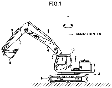
Sheet 1 of 22 from the published document. All sheets in the USPTO PDF
A device diagnostic apparatus (201) comprising: data judgment means (101) for, when device information (121) including operating condition information and internal state information is inputted, comparing the operating condition information of the device information with operating condition information stored in a database (111) beforehand to judge whether or not both of the operating condition information agree with each other, and then outputting judgment result information; and state diagnosis means (103) for, when the judgment result information indicates that both of the operating condition information agree with each other, comparing the internal state information in the device information with internal state information stored in the database beforehand, and then outputting the result of the comparison. This makes it possible to reduce the possibility that false judgment result will be output, and to achieve the efficiency of maintenance work.
Construction machines such as a large-size hydraulic excavator which operates in a mine or the like, and other working machines, are often required to continuously operate 24 hours per day and 365 days per year with almost no stopping. In such a case, before a machine is abnormally stopped, it is necessary to keep devices in perfect conditions by subjecting them to maintenance work beforehand. In general, a specialized maintenance person periodically performs inspection based on inspection work to check whether or not an abnormal state has occurred in any of the devices. If an abnormal state is detected, required maintenance work is performed to maintain the device in a good condition. On the other hand, the devices need to be stopped for inspection and maintenance work. Therefore, for an operation manager who wants to continuously operate the devices, the inspection and maintenance work
1 of 22 drawing sheets so far from the published document, cropped to the drawing. Every sheet is in the USPTO PDF.
What the patent claimed, word for word. All of it is now free to use.
The present invention relates to a device diagnostic apparatus, and a device diagnostic system, for diagnosing each of devices included in a working machine.
Construction machines such as a large-size hydraulic excavator which operates in a mine or the like, and other working machines, are often required to continuously operate 24 hours per day and 365 days per year with almost no stopping. In such a case, before a machine is abnormally stopped, it is necessary to keep devices in perfect conditions by subjecting them to maintenance work beforehand. In general, a specialized maintenance person periodically performs inspection based on inspection work to check whether or not an abnormal state has occurred in any of the devices. If an abnormal state is detected, required maintenance work is performed to maintain the device in a good condition.
On the other hand, the devices need to be stopped for inspection and maintenance work. Therefore, for an operation manager who wants to continuously operate the devices, the inspection and maintenance work will often be troublesome for operation while the devices operates normally.
In recent years, as is the case with a flight recorder of an airplane, a recorder is sometimes provided (a drive recorder; refer to patent document 1) on the main body of devices so that the recorder is made full use of in various ways. Various kinds of sensors are provided for the devices. Accordingly, inspection work to check whether or not maintenance work is required can be achieved by checking internal state information about the devices, which is output by the sensors. Heretofore, alarm information is usually output by a diagnostic circuit inside a device. However, at the moment when such alarm information is issued, a device state may have already become worse and, in the worst case, the operation of the device may stop. However, when an inspection is made by use of sensor information recorded in a recorder, the state that the device has failed can be known before the operation of the device stops. This makes it possible to make a maintenance plan. Recently, a diagnostic apparatus in which various kinds of sensor information recorded by a recorder is subjected to data processing by a computer is achieving widespread use.
As a processing method for processing the time series data, there are methods described in patent documents 2, 3. According to the method described in the patent document 2, a state which differs from a normal state is detected for the purpose of detecting illegal entrance into a computer network. According to the method described in the patent document 3, whether or not a movable body is in a moving state or in a stationary state is detected from a state of a radio wave at a communications terminal of the movable body.
In addition, patent document 4 proposes a technique in which diagnosis of a device is learned so as to make use of the learned diagnosis for the detection of an abnormal state.
Moreover, for example, patent documents 5, 6 describe a fault diagnostic apparatus of a working machine such as a hydraulic excavator. According to the patent document 5, the fault diagnosis includes the steps of: detecting, by each sensor, the state quantity relating to an operating state of an engine cooling water system of a hydraulic excavator; recording, as state quantity data, the state quantity detected by each sensor; comparing the recorded state quantity data with a specified reference value range corresponding to the state quantity data; and if the state quantity data is not within the reference value range, judging the state quantity data to be an abnormal state. According to the patent document 6, the processing includes the steps of: recording information, which are detected by each sensor for detecting the state quantity relating to an operating state of an intake and exhaust system of an engine, in a data recording device as input operation data, the information including intercooler inlet pressure, intercooler outlet pressure, an intercooler inlet temperature, intercooler outlet temperature, exhaust gas temperature of the engine, outdoor air temperature, engine speed, and a throttle position; recording, in the data recording device, comparison data to be compared with operation data; inputting the operation data and the comparison data, which have been recorded in the data recording device, into a display controller; and outputting the operation data and the comparison data on a display unit as display signals. Patent document 1: JP, A 2002-73153 Patent document 2: JP, A 2005-4658 Patent document 3: JP, A 2002-217811 Patent document 4: JP, A 2003-516275 Patent document 5: JP, A 2005-180225 Patent document 6:
Problems to be Solved by the Invention
For the methods described in the patent documents 2 and 3, if a working machine such as a hydraulic excavator is used, a change point at which a state changes is not clear; and a device state changes in various ways depending on operating environment conditions. Therefore, when a target whose state is difficult to judge only by partially checking time series information is inspected, the processing method for processing the time series information has a problem.
According to the patent document 4, because a learning function works only for an alarm set inside the device beforehand, an unknown abnormal state cannot be handled. Accordingly, there is a possibility that a false diagnosis will be made.
The patent documents 5 and 6 do not take into consideration the influence of the other state quantity for state quantity data used for abnormal state diagnosis. Therefore, also in this case, there is a possibility that a false diagnosis will be made.
An object of the present invention is to provide a device diagnostic apparatus and a device diagnostic system for diagnosing devices of a working machine which are capable of reducing the possibility that false judgment result will be output, and capable of achieving the efficiency of maintenance work.
Means for Solving the Problems
In order to achieve the above-described object, the present invention provides a device diagnostic apparatus of a working machine which includes a body, and a work device provided on the body. The device diagnostic apparatus diagnoses, as a target device, at least one of components included in the working machine. The device diagnostic apparatus includes data judgment means for, when device information including operating condition information and internal state information is inputted, comparing the operating condition information in the device information with operating condition information stored beforehand to judge whether or not both of the operating condition information agree with each other, and then outputting judgment result information, the operating condition information including external environment information of the target device and operation information of the target device, and the internal state information including operation state information of the target device; and state diagnosis means for, when the judgment result information indicates that both of the operating condition information agree with each other, comparing the internal state information in the device information with internal state information stored beforehand, and then outputting the result of the comparison.
Effects of the Invention
According to the present invention, it is possible to reduce the possibility that false judgment result will be output, and to achieve the efficiency of maintenance work.
FIG. 1 is a diagram illustrating a device diagnostic system according to one embodiment of the present invention;
FIG. 2 is a flowchart illustrating how a data judgment unit and a state diagnostic unit, which are included in a device diagnostic apparatus, operate according to one embodiment of the present invention;
FIG. 3 is a flowchart illustrating the operation of a diagnostic database update unit of the device diagnostic apparatus according to one embodiment of the present invention;
FIG. 4 is a diagram illustrating an example of device information according to one embodiment of the present invention;
FIG. 5 is a diagram illustrating the relationship between a learning period and a range of learning;
FIG. 6 is a diagram illustrating an example in which information output by the device diagnostic apparatus is displayed according to one embodiment of the present invention;
FIG. 7 is a diagram illustrating an example in which information output by the device diagnostic apparatus is displayed according to one embodiment of the present invention;
FIG. 8 is a diagram illustrating an example in which information output by the device diagnostic apparatus is displayed according to one embodiment of the present invention;
FIG. 9 is a diagram illustrating an example in which information output by the device diagnostic apparatus is displayed according to one embodiment of the present invention;
FIG. 10 is a diagram illustrating an example in which information output by the device diagnostic apparatus is displayed according to one embodiment of the present invention;
FIG. 11 is a diagram illustrating an example of the relationship between operating condition information (the outdoor air temperature) and internal state information (the radiator water temperature);
FIG. 12 is a diagram illustrating an example in which information output by the device diagnostic apparatus is displayed according to one embodiment of the present invention;
FIG. 13 is a diagram illustrating a device diagnostic system according to another embodiment of the present invention;
FIG. 14 is a flowchart illustrating how a data judgment unit and a state diagnostic unit, which are included in a device diagnostic apparatus, operate according to another embodiment of the present invention;
FIG. 15 is a diagram illustrating an example in which information output by the device diagnostic apparatus is displayed according to another embodiment of the present invention;
FIG. 16 is a diagram illustrating an example in which information output by the device diagnostic apparatus is displayed according to another embodiment of the present invention;
FIG. 17 is a diagram illustrating the structure of a large-size hydraulic excavator as a whole, and a device diagnostic system, according to still another embodiment of the present invention;
FIG. 18 is a diagram illustrating a controller network disposed in a cabin of a hydraulic excavator;
FIG. 19 is a diagram illustrating a pump mission unit that is one of components included in a hydraulic excavator;
FIG. 20 is a diagram schematically illustrating a mission oil cooling system and a hydraulic operating fluid cooling system accompanying with a hydraulic system and a pump mission unit;
FIG. 21 is a diagram illustrating an engine, and a cooling system thereof; and
FIG. 22 is a diagram illustrating a configuration of a device diagnostic apparatus included in the device diagnostic system according to the embodiment of the present invention shown in FIG. 17.
1 Hydraulic excavator 2 Track body 3 Swing body 4 Cabin 5 Front work device 6 Boom 7 Arm 8 Bucket 9 Data recording device 11 Personal computer 11A Personal computer main body 11B Display unit 11C Mouse 11D Keyboard 12 Server 13 Radio equipment 14 Communication satellite 15 Base station 16 Internet 21 Engine controller 22 Vehicle body controller 23 Monitor controller 24 Hydraulic system measurement unit 25 Engine measurement unit 27A First common communication line 27B Second common communication line 28 Electronic governor 29A, 29B Electric lever units 31 Display unit 32 Operation unit 40 Engine 41 Pump mission unit 42 Container 43 Oil pan 44 Upper oil accumulator 45 Suction unit 46 Oil filter 47 Gear pump 48 Mission oil cooler 51 through 53 Temperature sensors 55 Tank 56a, 56b Control valves 57 Actuator 58 Hydraulic operating fluid cooler 59 Drain pipe 60 Relief valve 61 Fan motor 62 Auxiliary pump 64 Solenoid valve 65, 68 Pressure sensors 66, 67, 69 Temperature sensors 71 Engine main body 72 Turbocharger 73a, 73b After-coolers 75 Radiator 76 LTA radiator 77 Coolant pump 79 Fan motor 82 through 85 Temperature sensors 86, 87 Pressure sensor 89 Tilt sensor 101, 101A Data judgment unit 102 Process learning means 103, 103A State diagnosis means 104 Diagnostic database update unit 111 Diagnostic database 111a Operating condition data storage unit 111b Internal state data storage unit 111c Maintenance information data storage unit 112 Process database 120 Attribute information database 121 Device information (sensor information and attribute information) 121A Sensor information 121B Attribute information 201, 201A, 201B Device diagnostic apparatus 202 Input unit 204 Display unit P1, P2, P3 Main pumps
Each embodiment will be described below with reference to drawings.
First Embodiment
A diagnostic apparatus according to one embodiment of the present invention will be described below with reference to FIGS. 1 through 16.
According to this embodiment, various kinds of components included in a working machine (for example, a hydraulic excavator) such as a construction machine are described as target devices to be diagnosed.
FIG. 1 is a diagram illustrating a configuration of a device diagnostic system according to this embodiment. The device diagnostic system includes a device diagnostic apparatus 201, an input unit 202, and a display unit 204. The device diagnostic apparatus 201 includes a data judgment unit 101, a process learning unit 102, a state diagnostic unit 103, a diagnostic database update unit 104, a diagnostic database 111, and a process database 112.
First of all, the data judgment unit 101 receives device information 121 to be input from the outside. The device information 121 indicates a state of a target device to be diagnosed. The inputted device information 121 includes operating condition information and internal state information. As shown in FIG. 4, the operating condition information includes external environment information of the target device, operation information of the target device, and information about the operation of the target device, and indicates conditions such as environment and way under which the target device has been operated. For example, the operating condition information includes: outdoor air temperature data, device operation data, humidity data, meteorological data such as weather data and road surface data indicating a state of a road surface, operation data such as how an accelerator is stepped, and the roughness of operation, driver data such as the distinction of, age, and a skill level, and the like. The internal state information is operation state information which indicates how the target device has been moved under the above-described operating conditions. To be more specific, the internal state information includes sensor information by various kinds of sensors provided in the target device. For example, the sensor information includes engine speed data, radiator water temperature data, oil temperature data, fuel consumption data, sound data about the sound generated by the target device, vibration data, and the like.
The data judgment unit 101 into which the device information 121 has been inputted refers to the diagnostic database 111. The diagnostic database 111 is constituted of an operating condition data storage unit 111a, an internal state data storage unit 111b, and a maintenance information data storage unit 111c. The operating condition data storage unit 111a and the internal state data storage unit 111b stores, respectively, the operating condition information and the internal state information, both of which are included in the device information 121.
Incidentally, the operating condition information stored in the operating condition data storage unit 111a and the internal state information stored in the internal state data storage unit 111b are stored with associated manner with each other. In addition, maintenance information stored in the maintenance information data storage unit 111c is associated with the operating condition information stored in the operating condition data storage unit 111a and the internal state information stored in the internal state data storage unit 111b.
The data judgment unit 101 searches whether the operating condition data storage unit 111a in which the operating condition information has been stored beforehand includes information that agrees with operating condition information in the inputted device information 121. To be more specific, the data judgment unit 101 compares the operating condition information in the inputted device information 121 with the operating condition information stored beforehand in the operating condition data storage unit 111a to judge whether or not both of the operating condition information agree with each other. When it is judged that the operating condition information stored beforehand in the operating condition data storage unit 111a includes the data which agrees with the operating condition information in the inputted device information 121, the data judgment unit 101 reads, from the internal state data storage unit 111b, internal state information corresponding to the operating condition information in the operating condition data storage unit 111a, and then outputs the read internal state information and the inputted device information 121 with both of them associated with each other, as judgment result information, to the state diagnostic unit 103.
The state diagnostic unit 103 compares the internal state information included in the inputted device information with the internal state information stored beforehand in the internal state data storage unit 111b, and then outputs the result of the comparison. As a result of the comparison, when the internal state information stored beforehand in the internal state data storage unit 111b includes data that agrees with the internal state information included in the inputted device information, maintenance information indicating whether the target device is "normal" or "abnormal" is read from the maintenance information data storage unit 111c. When the maintenance information indicates that the target device is "normal", the diagnostic result indicating normal state is output to the display unit 204 located outside of the device diagnostic apparatus. When the maintenance information indicates that the target device is "abnormal", the diagnostic result indicating any one of an abnormal component, a detailed description of the abnormal state, and a detailed description of measures taken (or a combination of them) is output to the display unit 204. Moreover, when a rate of change included in the internal state information is recognized, and when the date on which the abnormal state exerts an influence upon an operation situation of the target device can be expected, the date is also output to the display unit 204 together with the above-described information.
FIG. 12 illustrates a display screen 1101 that is an example in which the display unit 204 displays the diagnostic result. In this example, the abnormal component, the detailed description of the abnormal state, the detailed description of measures taken, and the date expected to be influenced are displayed on the display screen 1101. Users (including an operator, and an operation manager) who view the display screen 1101 can judge when, which and how part of the target device should be maintained. These pieces of maintenance information are inputted or selected by the diagnostic database update unit 104, and are then stored in the maintenance information data storage unit 111c (described later).
On the other hand, as a result of the comparison made by the state diagnostic unit 103 between the internal state information included in the inputted device information and the internal state information stored beforehand in the internal state data storage unit 111b, when it is judged that the internal state information stored beforehand in the internal state data storage unit 111b does not include the data that agrees with the internal state information included in the inputted device information, diagnostic result indicating that the target device may be abnormal is output to the display unit 204 to perform the preventive maintenance.
The judgment that the internal state information stored beforehand in the internal state data storage unit 111b does not include the data that agrees with the internal state information included in the inputted device information has two cases. The one is a case where the internal data storage unit 111b includes only the internal state information in which the maintenance information indicates "normal," and the other case is that the internal data storage unit 111b includes only the internal state information in which the maintenance information indicates "abnormal." However, when process learning information is added to the diagnostic database 111, and the diagnostic database 111 is updated, the addition or the update is usually made on the basis of the process learning information obtained in the case where the maintenance information indicates "normal." Accordingly, when the internal state information stored beforehand in the internal state data storage unit 111b does not include the data that agrees with the inputted internal state information, there is a high possibility that only the internal state information in which the maintenance information indicates "abnormal" may be included. Therefore, in this case, in order to perform the preventive maintenance, the state diagnostic unit 103 outputs the diagnostic result that the target device may be abnormal to the display unit 204.
Next, the data judgment unit 101 searches whether the operating condition data storage unit 111a includes information that agrees with the operating condition information in the inputted device information 121. To be more specific, the data judgment unit 101 compares the operating condition information in the inputted device information 121 with the operating condition information stored beforehand in the operating condition data storage unit 111a to judge whether or not both of them agree with each other. As a result of the judgment, when it is judged that the operating condition information stored beforehand in the operating condition data storage unit 111a does not include the data which agrees with that in the inputted device information 121, disagreement information indicating that an operating condition is a factor of the disagreement is output to the process learning unit 102, together with the inputted device information (including both the operating condition information and the internal state information). For example, as shown in FIG. 5, on the assumption that, among pieces of operating condition information that have already been reflected in the diagnostic database 111, the outdoor air temperature data has been learned on the basis of a "learning period A" shown in the figure, learned data of the diagnostic database 111 exists within a temperature range from Ta to Tb shown in the figure. However, in the case where the target device is actually used under such operating conditions as exceeding a learned range, with the passage of time, the temperature range may be extended to that shown in the figure, that is, from Td to Tc. In this case, two learned temperature out-of-range periods B and C become unlearning periods. Usually, in such a case, if diagnosis is carried out by use of the diagnostic database 111 just as it is, although the target device is normal, misjudgment will occur because of a shortage of learning, which is a problem.
Therefore, when device information including operating condition information which is not stored in the diagnostic database 111 is inputted to the judgment unit 101 (when the judgment result information output from the data judgment unit 101 indicates disagreement), the process learning unit 102 learns this device information, and then stores the learned device information in the process database 112 as process learning information. FIG. 6 is a diagram illustrating a notification screen 601 for notifying a user (not illustrated) of the system shown in FIG. 17 that the learned device information is stored in the process database 112. When inputted device information including operating condition information which is not stored in the diagnostic database 111 is inputted to the data judgment unit 101 (in other words, if unlearned data has been inputted), the process learning unit 102 instructs the display unit 204 to display a message stating that unlearned data has been detected, and also to display a message stating that the unlearned data is stored as process learning information, as well as the date and time at which the unlearned data is stored. In the example shown in FIG. 6, two periods which correspond to the learned temperature out-of-range periods B and C shown in FIG. 5 respectively are displayed as follows:
B: from 2007/11/01 18:30 to 2008/03/31 15:30
C: from 2008/05/12 12:30 to 2008/09/20 09:00
The above process flow will be described with reference to a flowchart shown in FIG. 2. First of all, the data judgment unit 101 judges whether or not the device information 121 has been inputted (S201). When it is judged that the device information 121 has been inputted, the data judgment unit 101 refers to information stored in the operating condition data storage unit 111a to judge whether or not the information stored in the operating condition data storage unit 111a includes data that agrees with operating condition information in the device information 121 (S202). When the data which agrees with the operating condition information in the device information 121 is detected, the data judgment unit 101 outputs the inputted device information 121 to the state diagnostic unit 103. The state diagnostic unit 103 makes a diagnosis of the device information 121 with reference to the diagnostic database 111 (S203), and then outputs the diagnostic result to an outside display unit, or the like (S204). When the data which agrees with the operating condition information in the device information 121 is not detected in the operating condition data storage unit 111a, the data judgment unit 101 outputs the device information 121 to the process learning unit 102. The process learning unit 102 learns the device information 121 (S205), and then stores the learned device information in the process database 112 as process learning information (S206).
The user (not illustrated) of the system shown in FIG. 17 use the input unit 202 and a process learning display request screen (not illustrated) on the display unit 204 to read process learning information from the process database 112, and then a process learning information list screen 701 as shown in FIG. 7 can be displayed on the display unit 204. It is to be noted that the process database 112 stores the process learning information and date data of the date on which the process learning information has been learned, with both of them associated with each other. Accordingly, the display unit can display the process learning information and the date data of the date on which the process learning information has been learned, in an associated manner with each other. In the example illustrated in the figure, disagreement information which is process learning information output from the process learning unit 102 is displayed as follows: a disagreement period is displayed on the upper side of each field of the list screen 701; and a reason of the disagreement such as "disagreement of operation data", and "disagreement of outdoor air temperature data" is displayed on the lower side of each field of the list screen 701. In addition, disagreement information displayed in fields 2 and 3 correspond to the learned temperature out-of-range periods B and C respectively.
The diagnostic database update unit 104 detects whether or not the process database 112 has been updated. When it is detected that the process database 112 has been updated, the diagnostic database update unit 104 outputs process database update request information. The process database update request information is displayed on the display unit 204 as diagnostic database update request screens 801 and 802. As shown in FIG. 8, each of the diagnostic database update request screens 801 and 802 displays, for example, a comment of "the process learning information will be reflected in the diagnostic database", and a target period of data, and a request which prompts the user to input or select whether or not the target device has been normal during the period. The diagnostic database update request screen 801 corresponds to the learned temperature out-of-range period B, whereas the diagnostic database update request screen 802 corresponds to the learned temperature out-of-range period C.
The user (not illustrated) of the system shown in FIG. 17 checks a device state for the period during which the data is targeted, and then notifies the diagnostic database update unit 104 of an abnormal state judgment result indicating that the target device has been normal or abnormal during the target period. The notification of the abnormal state judgment is performed by clicking or selecting a "Normal" button or an "Abnormal" button displayed on the diagnostic database update request screens 801 and 802, or by inputting the abnormal state judgment result. Here, the abnormal state judgment result is inputted through the diagnostic database update request screens 801 and 802 by use of the input unit 202. The input unit 202 is a keyboard, or a mouse, used by the user (not illustrated) of the system shown in FIG. 17. The diagnostic database update request screens 801 and 802 and the input unit 202 constitute maintenance information input means.
When the user (not illustrated) of the system shown in FIG. 17 selects "normal" as the abnormal state judgment result (more specifically, when the user inputs maintenance information indicating "normal" through the diagnostic database update request screen 801 by use of the input unit 202), the diagnostic database update unit 104 adds process learning information (corresponding to the device information) together with the abnormal state judgment result "normal" to the information stored in the maintenance information data storage unit 111c of the diagnostic database 111 as diagnostic information and updates the data thereof. FIG. 9 is a diagram illustrating an example of a notification screen of the display unit 204, the notification screen being used to notify the user of update of the diagnostic database when the diagnostic database has been updated. This notification screen is displayed when the target device has been normal during the learned temperature out-of-range period B displayed in the diagnostic database update request screen 801 of FIG. 8. The notification screen 901 shown in FIG. 9 displays a message stating that the process learning information has been reflected in the diagnostic database by the diagnostic database update unit 104, as well as the date and time on which the process learning information has been reflected.
When the user (not illustrated) of the system shown in FIG. 17 selects "abnormal" as the abnormal judgment result (more specifically, when the user inputs maintenance information indicating "abnormal" through the diagnostic database update request screen 802 by use of the input unit 202), the diagnostic database update unit 104 instructs the display unit 204 to display a maintenance information input screen 1001 that requests the user to input data such as a failure period, an abnormal component, a detailed description of the abnormal state, and a detailed description of measures taken, into fields as shown in FIG. 10. The maintenance information input screen 1001 is displayed when a failure has occurred in the target device during the learned temperature out-of-range period C which is displayed on the diagnostic database update request screen 802 in FIG. 8. In this case, "from 2008/06/20 09:00 to 2008/08/01 12:00", "radiator", "poor cleaning", and "cleaning" are inputted into the fields of the failure period, the abnormal component, the detailed description of the abnormal state, and the detailed description of measures taken respectively.
FIG. 11 is a graph illustrating an example of the relationship between the outdoor air temperature and the water temperature of a radiator in a case where operating condition information is the outdoor air temperature, and internal state information is the radiator water temperature. When the outdoor air temperature changes as shown in FIG. 5, the radiator water temperature also analogously changes under the influence of the outdoor air temperature. The learned temperature out-of-range period B is a period during which the target device is kept normal. In contrast, the learned temperature out-of-range period C is a period including the failure time at which a failure has occurred in the target device. In the learned temperature out-of-range period B, the ratio of the change in the radiator water temperature relative to the outdoor air temperature is substantially the same as that in water temperature Ra relative to the outdoor temperature in the learning period A. In a region D ranging from the time t1 to the time t2, the period D being included in the learned temperature out-of-range period C, the ratio of the change in the radiator water temperature relative to the outdoor air temperature is more steeply in comparison with that in the other periods. The highest radiator water temperature is shown at the time t2. A cause of the steep change in radiator water temperature in the period D is, for example, adhesion of a large amount of dust to a radiation fin of the radiator. Accordingly, cleaning of the radiator by a maintenance person at the time t2 makes it possible to return the steep change in radiator water temperature to a normal change thereafter.
The working machine is equipped with a data recording device for recording device information 121 (described later). The user of the system shown in FIG. 17 can know the change in radiator water temperature in the past by displaying data of the radiator water temperature recorded in the data recording device on the display unit. On the basis of the radiator water temperature data, the user of the system shown in FIG. 17 inputs the period D (a specified period that starts from a point of time before the time t2 at which the abnormal change in radiator water temperature becomes the largest, and that includes the time t2) into the field of the failure period shown in FIG. 10.
On the completion of the input of the data into the maintenance information input screen 1001 by the user using the input unit 202, the diagnostic database update unit 104 adds, as diagnostic information, the input data and the abnormal state judgment result "abnormal" to the information stored in the maintenance information data storage unit 111c of the diagnostic database 111 and updates the data thereof. At the same time, process learning information (operating condition information (for example, the outdoor air temperature) and internal state information (for example, the radiator water temperature) at this point of time) are stored in the operating condition data storage unit 111a and the internal state data storage unit 111b with the maintenance information in question associated with. In this case, the abnormal state judgment result "abnormal" is added to the maintenance information corresponding to the internal state information (the water temperature of the radiator) in the period D. Thus, diagnosis for the preventive maintenance of the target device (radiator) and associated devices thereof can be performed since the maintenance information corresponding to the internal state information (the radiator water temperature) in the period D indicates "abnormal". The period D starts not from the time at which the failure has occurred but from the time t1 at which the water temperature of the radiator has steeply changed. To be more specific, after the learned temperature out-of-range period B, the outdoor air temperature and the radiator water temperature change as shown in the period C shown in FIG. 11, and when the internal state information included in the inputted device information to be compared in the state diagnostic unit 103 agrees with the internal state information included in the internal state data storage unit 111b, maintenance information indicates "abnormal" which is started from a point of time immediately after the start of the period D. The diagnostic result is then output to the display unit 204. As a result, an abnormal state can be diagnosed before a failure occurs. This enables maintenance work for the preventive maintenance.
The above process flow will be described with reference to a flowchart shown in FIG. 3.
First of all, the diagnostic database update unit 104 reads process learning information from the process database 112 (S301). A judgment is made as to whether or not a user (not illustrated) has inputted maintenance information through the maintenance information input screen 1001 (S302). As a result of the judgment, when it is judged that the maintenance information has been inputted, the diagnostic database update unit 104 reads the maintenance information, and then adds the maintenance information to the read process learning information. Next, the diagnostic database update unit 104 adds the read process learning information and the maintenance information, as diagnostic information, to the information stored in the maintenance information data storage unit 111c of the diagnostic database 111 and updates the data thereof. At the same time, the diagnostic database update unit 104 stores the process learning information (the operating condition information and the internal state information at this point of time) in the operating condition data storage unit 111a and the internal state data storage unit 111b (S304).
As described above, the device information is divided into the operating condition information and the internal state information and they are separately recorded, and the maintenance information is added to the operation condition information and the internal state information. This makes it possible to increase the judgment accuracy of the diagnostic apparatus.
Second Embodiment
Another embodiment different from the first embodiment will be described below with reference to FIGS. 13 through 16 with a focus placed on points which is different from the first embodiment.
FIG. 13 is a diagram illustrating a configuration of a device diagnostic system according to this embodiment. FIG. 14 is a diagram illustrating the process flow of data judgment means of the device diagnostic apparatus.
First of all, referring to FIG. 13, the data judgment unit 101A and the state diagnostic unit 103A, both of which are included in the device diagnostic apparatus 201A of the device diagnostic system according to this embodiment, differ in function from those shown in FIG. 1.
The description continues in the full USPTO document.
About 6,238 words. The USPTO PDF has it with every drawing.
Fees are due 3.5, 7.5 and 11.5 years after grant. This patent expired on September 10, 2025, so the fee marked "not paid" was the one that went unpaid.
APPARATUS AND SYSTEM FOR DIAGNOSING DEVICES INCLUDED IN WORKING MACHINE
Filed Aug 2008 · published Mar 2010Apparatus and system for diagnosing devices included in working machine
Filed Aug 2008 · granted Sep 2013Earlier publications, parents and continuations. None of them can still be enforced, or this patent would not be listed.
Prior art cited by the examiner or applicant. Useful when you check your own idea for novelty.
Everything on this page comes from the documents linked above.