Background of the invention
1. Field of the invention
This invention relates to a charging member, a process cartridge and an electrophotographic apparatus.
2. Description of the related art
Japanese Patent Application Laid-open No. 2008-276026 discloses, as a charging member which is brought into contact with an electrophotographic photosensitive member to charge the electrophotographic photosensitive member electrostatically, a charging member having on its surface protrusions derived from conductive resin particles. Then, it discloses that such a charging member can keep any dot-like or horizontal line-like image defects from occurring on electrophotographic images; the defects being caused by stains of a toner, external additives and the like having come deposited on the surface of the charging member.
Summary of the invention
However, when the charging member according to Patent Literature 1 is used in contact charging, it has come about that the surface of the electrophotographic photosensitive member comes to wear non-uniformly as a result of its long-term service. Studies made by the present inventors on the reason therefor have revealed that, at the nip between the charging member and the electrophotographic photosensitive member, the pressure of contact therebetween concentrates at the protrusions derived from conductive resin particles of the surface of the charging member to make the surface of the electrophotographic photosensitive member scraped off non-uniformly.
Accordingly, the present invention is directed to providing a charging member that brings out stable charging performance over a long period of time and also makes the surface of the electrophotographic photosensitive member not easily come to wear non-uniformly. Further, the present invention is directed to providing a process cartridge and an electrophotographic apparatus that contribute to stable formation of high-grade electrophotographic images.
According to one aspect of the present invention, there is provided a charging member comprising a conductive substrate and a conductive resin layer, the conductive resin layer comprising a binder, conductive fine particles, and bowl-shaped resin particles each of which has an opening, the bowl-shaped resin particles being contained in the conductive resin layer in such a way as not to be exposed to the surface of the charging member, and the surface of the charging member having concavities derived from openings of the bowl-shaped resin particles and protrusions derived from edges of the openings of the bowl-shaped resin particles.
According to another aspect of the present invention, there is provided a process cartridge comprising the above charging member and an electrically chargeable body, both of which are integrally joined, and being so constituted as to be detachably mountable to the main body of an electrophotographic apparatus. According to a further aspect of the present invention, there is provided an electrophotographic apparatus comprising the above charging member, an exposure unit and a developing assembly.
According to the present invention, a charging member is obtained which can stably electrostatically charge the electrophotographic photosensitive member and also can keep the surface of the electrophotographic photosensitive member from coming to wear non-uniformly. According to the present invention, a process cartridge and an electrophotographic apparatus are also obtained which can stably form high-grade electrophotographic images.
Brief description of the drawings
FIG. 1A is a sectional view showing an example of layer configuration of the charging member (roller shaped) according to the present invention.
FIG. 1B is a sectional view showing another example of layer configuration of the charging member (roller shaped) according to the present invention.
FIG. 1C is a sectional view showing still another example of layer configuration of the charging member (roller shaped) according to the present invention.
FIG. 1D is a sectional view showing a further example of layer configuration of the charging member (roller shaped) according to the present invention.
FIG. 2A is a partial sectional view showing an example of how the charging member according to the present invention is in the vicinity of its surface.
FIG. 2B is a partial sectional view showing another example of how the charging member according to the present invention is in the vicinity of its surface.
FIG. 2C is a partial sectional view showing still another example of how the charging member according to the present invention is in the vicinity of its surface.
FIG. 2D is a partial sectional view showing a further example of how the charging member according to the present invention is in the vicinity of its surface.
FIG. 3 is a partial sectional view showing a profile of the charging member according to the present invention in the vicinity of its surface.
FIG. 4A is an illustration showing an example of the shape of the bowl-shaped resin particles used in the present invention.
FIG. 4B is an illustration showing another example of the shape of the bowl-shaped resin particles used in the present invention.
FIG. 4C is an illustration showing still another example of the shape of the bowl-shaped resin particles used in the present invention.
FIG. 4D is an illustration showing a further example of the shape of the bowl-shaped resin particles used in the present invention.
FIG. 4E is an illustration showing a still further example of the shape of the bowl-shaped resin particles used in the present invention.
FIG. 5 is a view of an instrument for measuring the electrical resistance value of a charging roller.
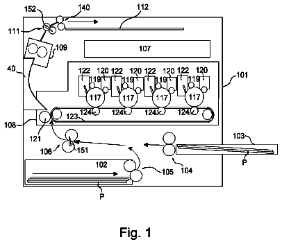
FIG. 6 is a schematic sectional view of an embodiment of the electrophotographic apparatus according to the present invention.
FIG. 7 is a sectional view of a cross-head extrusion equipment used in producing a charging roller.
FIG. 8 is an enlarged view of the charging member according to the present invention and an electrophotographic apparatus in the vicinity of a nip between them.
Description of the embodiments
Preferred embodiments of the present invention will now be described in detail in accordance with the accompanying drawings.
FIG. 1A shows a cross section of the charging member according to the present invention. The charging member has a conductive substrate 1 and a conductive resin layer 3 which covers the former on its peripheral surface. Then, the conductive resin layer 3 contains a binder, conductive fine particles and bowl-shaped resin particles. As shown in FIG. 1B, the conductive resin layer 3 may be formed of a first conductive resin layer 31 and a second conductive resin layer 32. As also shown in FIGS. 1C and 1D, a conductive elastic layer 2 may be formed between the conductive substrate 1 and the conductive resin layer 3.
Conductive Resin Layer:
FIGS. 2A and 2B are enlarged sectional views of surface portions of the charging member according to the present invention. The conductive resin layer 3 as a surface layer is incorporated therein with bowl-shaped resin particles 61 standing unexposed to the surface of the charging member. Also, concavities 52 derived from openings 51 of the bowl-shaped resin particles and protrusions 54 derived from edges 53 of the openings of the bowl-shaped resin particles stand formed on the surface of the charging member.
FIGS. 2C and 2D show examples in which each conductive resin layer 3 is formed of the first conductive resin layer 31 and the second conductive resin layer 32. In the first conductive resin layer 31, bowl-shaped resin particles 61 are present in such a way that its openings are exposed to the surface of the first conductive resin layer 31 and edges of the openings constitute protrusions. The surface of such a first conductive resin layer is covered with the second conductive resin layer 32 so that the bowl-shaped resin particles 61 may stand unexposed to the surface. Then, the second conductive resin layer 32 is formed along inner walls of the bowl-shaped resin particles 61, and hence concavities derived from the openings of the bowl-shaped resin particles are formed on the surface of the second conductive resin layer constituting the surface of the charging member. Further, the second conductive resin layer covers the edges of the openings of the bowl-shaped resin particles 61, thus protrusions derived from the edges are formed on the surface of the second conductive resin layer.
It has been found that such a charging member the conductive resin layer of which is incorporated with the bowl-shaped resin particles standing unexposed to the surface and which has the concavities derived from the openings of the bowl-shaped resin particles and the protrusions derived from the edges of the openings can not easily scrape off the surface of the electrophotographic photosensitive member even as a result of its long-term service.
With regard to the charging performance, a finding has also been obtained such that charging performance is achieved which is at the same level as that of any charging members having the protrusions derived from resin particles.
That is, observations on how the charging member according to the present invention and the electrophotographic photosensitive member come into contact with each other and are rotated have revealed that the protrusions derived from the edges of the openings are kept in contact with the surface of the electrophotographic photosensitive member and the concavities derived from the openings have made empty spaces form inside the nip between the electrophotographic photosensitive member and the charging member.
It has further been ascertained that, compared with the protrusions derived from conventional conductive fine particles, the protrusions derived from the edges of the openings deform elastically at the time they come into contact with the surface of the electrophotographic photosensitive member. FIG. 8 is an enlarged diagrammatic view of a nip between the charging member according to the present invention and an electrophotographic photosensitive member. At the nip, the edges 53 of the openings of bowl-shaped resin particles 61 are considered to deform elastically in the directions of arrows A in virtue of the pressure of their contact with an electrophotographic photosensitive member 803. It is considered that the reason why the charging member according to the present invention can not easily scrape off the surface of the electrophotographic photosensitive member is that the pressure of contact that is to be applied to the electrophotographic photosensitive member stands lessened because the edges 53 of the openings of bowl-shaped resin particles have elastically deformed.
Further observations on how the charging member according to the present invention comes into contact with the electrophotographic photosensitive member at the nip between them have revealed that empty spaces are kept to form between the surface of the charging member and the surface of the electrophotographic photosensitive member also in the interior of the nip between the charging member and the electrophotographic photosensitive member (801 in FIG. 8). Through such empty spaces, any discharge takes place from the conductive resin layer of the surface of the charging member to the surface of the electrophotographic photosensitive member, thus the phenomenon of discharge that is considered to usually take place only before and behind the nip takes place also inside the nip, as so considered. As the result, the charging member according to the present invention can bring out stable charging performance, as so considered.
Still further, the present inventors have also reached a finding that such a phenomenon of discharge inside the nip takes place because the inner walls of the bowl-shaped resin particles are covered (lined) with the conductive resin layer.
As shown in FIG. 3, each top (or peak top) 55 of protrusions 54 derived from the edges of openings of the bowl-shaped resin particles and each bottom 56 of concavities 52 derived from the openings of the bowl-shaped resin particles may preferably be in a top-to-bottom distance 57 of from 5 .mu.m or more to 100 .mu.m or less, and particularly preferably from 8 .mu.m or more to 80 .mu.m or less. Inasmuch as the top-to-bottom distance is set within this range, the pressure of contact of the charging member with the electrophotographic photosensitive member can more surely be lessened, and the empty spaces inside the nip between them can be retained. Also, the ratio of maximum diameter 58 in each particle of the bowl-shaped resin particles to the top-to-bottom distance 57 between the top 55 of each protrusion and the bottom 56 of each concavity, i.e., the value of (maximum diameter)/(top-to-bottom distance) may preferably be from 0.8 or more to 3.0 or less. Inasmuch as the ratio is set within this range, the aforesaid pressure of contact can more surely be lessened, and the empty spaces inside the nip can be retained.
Upon formation of an uneven-surface profile that comes from the above bowl-shaped resin particles, it is preferable for the surface condition of the conductive resin layer to have been so controlled as to be the following. The conductive resin layer may preferably have a ten-point average surface roughness (Rzjis) of from 5 .mu.m or more to 65 .mu.m or less, and particularly preferably from 10 .mu.m or more to 50 .mu.m or less. Its surface may also preferably have a hill-to-dale average distance (Sm) of from 30 .mu.m or more to 200 .mu.m or less, and particularly preferably from 40 .mu.m or more to 150 .mu.m or less. Inasmuch as the Rzjis and Sm are set within these ranges, the aforesaid pressure of contact can more surely be lessened. The empty spaces inside the nip can also be retained. How to measure the ten-point average surface roughness (Rzjis) and hill-to-dale average distance (Sm) is detailed later.
Examples of the bowl-shaped resin particles used in the present invention are shown in FIGS. 4A to 4E. That is, "bowl-shaped" in the present invention refers to the shape that the particles have openings 71 and have roundish concavities 72 at the openings. The openings may have, as shown in FIGS. 4A and 4B, flat edges, or, as shown in FIGS. 4C to 4D, uneven edges. The bowl-shaped resin particles may preferably have, in each particle thereof, a maximum diameter of from 5 .mu.m or more to 150 .mu.m or less, and particularly preferably from 8 .mu.m or more to 120 .mu.m or less. Inasmuch as the maximum diameter is within this range, the discharge inside the nip can more surely be made to takes place.
The ratio of the maximum diameter 58 in each particle of the bowl-shaped resin particles to minimum diameter 74 in each of the openings, i.e., the value of (maximum diameter)/(opening minimum diameter) in each particle of the bowl-shaped resin particles may preferably be from 1.1 or more to 4.0 or less. Inasmuch as the ratio is so set, the aforesaid pressure of contact can more surely be lessened, and the empty spaces inside the nip can be retained.
Peripheral edges of the openings of the bowl-shaped resin particles may each preferably have a difference between outer diameter and inner diameter, of from 0.1 .mu.m or more to 3 .mu.m or less, and particularly preferably from 0.2 .mu.m or more to 2 .mu.m or less. Inasmuch as the difference is within this range, the aforesaid pressure of contact can more surely be lessened. Also, it is further preferable that such a difference between outer diameter and inner diameter is formed over the whole particles and substantially uniformly. What is meant by "substantially uniform" is that the difference is in the range of within .+-.50% of average value.
Binder:
As the binder, any known rubber or resin may be used. As the rubber, it may include, e.g., natural rubbers or those which have been subjected to vulcanization treatment, and synthetic rubbers. The synthetic rubbers may include the following: Ethylene-propylene rubber, styrene-butadiene rubber (SBR), silicone rubbers, urethane rubbers, isoprene rubber (IR), butyl rubber, acrylonitrile-butadiene rubber (NBR), chloroprene rubber (CR), acrylic rubbers, epichlorohydrin rubber and fluorine rubbers. As the resin, any of resins such as thermosetting resins and thermoplastic resins may be used, for example. In particular, preferred are fluorine resins, polyamide resins, acrylic resins, polyurethane resins, silicone resins and butyral resins. Any of these may be used alone, or may be used in the form of a mixture of two or more types. Also, monomers which are raw materials for the binder may be copolymerized to make a copolymer.
Where the conductive resin layer is formed of the first conductive resin layer and the second conductive resin layer, it is preferable to use the rubber as the binder used for the first conductive resin layer. This is because the pressure to be applied to the bowl-shaped resin particles shows a tendency to be more readily lessened. In the case when the rubber is used as the binder used for the first conductive resin layer, it is preferable to use the resin as the binder used for the second conductive resin layer. This is because its close contact and rubbing with the electrophotographic photosensitive member can more easily be controlled. The conductive resin layer may be formed by curing or cross-linking a mixture obtained by adding a cross-linking agent to raw materials of a binder made into a prepolymer. In the present invention, such a mixture is hereinafter also termed as the binder to provide a description.
Conductive Fine Particles:
The conductive resin layer contains known conductive fine particles in order to bring out its electrical conductivity. As specific examples of the conductive fine particles, they may include fine metal oxide particles, fine metal particles and carbon black. Any of these conductive fine particles may be used alone or in combination of two or more types. The conductive fine particles in the conductive resin layer may be in a content of approximately from 2 parts by mass to 200 parts by mass, and particularly from 5 parts by mass to 100 parts by mass, based on 100 parts by mass of the binder. The binder and conductive fine particles used in the first conductive resin layer and second conductive resin layer may be the same or may be different. The conductive resin layer contains the bowl-shaped resin particles standing unexposed to the surface, and hence it is preferable for the first conductive resin layer and second conductive resin layer to have adherence to and affinity for each other.
How to Form Conductive Resin Layer:
How to form the conductive resin layer is described below.
--Method 1--
In Method 1, first, a cover layer in which conductive fine particles and hollow resin particles have been dispersed in the binder (hereinafter also "preliminary cover layer") is formed on the conductive substrate. Then, its surface is sanded so as to cut away part of the hollow resin particles to make them bowl-shaped. Thus, the concavities derived from the openings of the bowl-shaped resin particles and the protrusions derived from the edges of the openings of the bowl-shaped resin particles are formed on the surface (hereinafter also "uneven-surface profile coming from the openings of the bowl-shaped resin particles"). The preliminary cover layer is sanded in this way to first form the first conductive resin layer. Further, on its surface, the second conductive resin layer is formed. This enables the bowl-shaped resin particles to stand unexposed to the surface.
Dispersion of Resin Particles in Preliminary Cover Layer:
How to disperse the hollow resin particles in the preliminary cover layer is described first.
As one method, a method is available in which a coating of a conductive resin composition in which hollow particles having a gas in their interiors stand dispersed together with the binder and the conductive fine particles is formed on the conductive substrate and then the coating formed is, e.g., dried, cured or cross-linked. As a material used for the hollow resin particles, it may include the known resins described previously.
As another method, a method may be exemplified which makes use of what is called thermally expandable microcapsules the particles of which contain in their interiors an encapsulated substance, where heat is applied to make the encapsulated substance expand to come into the hollow resin particles. It is a method in which a conductive resin composition is prepared in which the thermally expandable microcapsules stand dispersed together with the binder and the conductive fine particles, and a layer of this composition is formed on the conductive substrate and then, e.g., dried, cured or cross-linked. In the case of this method, the encapsulated substance may be made to expand by the heat supplied when the binder used in the preliminary cover layer is dried, cured or cross-linked, to form the hollow resin particles. In this course, their particle diameter and so forth may also be controlled by controlling temperature conditions and so forth.
In the case when the thermally expandable microcapsules are used, it is necessary to use a thermoplastic resin as the binder. Examples of the thermoplastic resin are given below: Acrylonitrile resin, vinyl chloride resin, vinylidene chloride resin, methacrylic acid resin, styrene resins, urethane resins, amide resins, methacrylonitrile resin, acrylic acid resin, acrylate resins, methacrylate resins and so forth. Of these, it is preferable to use a thermoplastic resin composed of at least one selected from acrylonitrile resin, vinylidene chloride resin and methacrylonitrile resin, as having a low gas permeability and exhibiting a high impact resilience. Any of these thermoplastic resins may be used alone or in combination of two or more types. Further, monomers for any of these thermoplastic resins may be copolymerized so as to be used as a copolymer.
As the substance to be entrapped in the thermally expandable microcapsules, one capable of vaporizing at a temperature not higher than the softening point of the thermoplastic resin used as the binder is preferred, and may include, e.g., the following: Low-boiling liquids such as propane, propylene, butane, normal butane, isobutane, normal pentane and isopentane; and high-boiling liquids such as normal hexane, isohexane, normal heptane, normal octane, isooctane, normal decane and isodecane.
The thermally expandable microcapsules may be produced by any known production process such as a suspension polymerization process, an interfacial polymerization process, an interfacial precipitation process or a solvent evaporation process. For example, in the suspension polymerization process, a method may be exemplified in which a polymerizable monomer(s), the substance to be entrapped in thermally expandable microcapsules and a polymerization initiator are mixed, the mixture obtained is dispersed in an aqueous medium containing a surface-active agent or a dispersion stabilizer and thereafter suspension polymerization is carried out. Here, a compound having a reactive group capable of reacting with functional groups of the polymerizable monomer, an organic filler and so froth may also be added.
As the polymerizable monomer, it may be exemplified by the following: Acrylonitrile, methacrylonitrile, .alpha.-chloroacrylonitrile, .alpha.-ethoxyacrylonitrile, fumaronitrile, acrylic acid, methacrylic acid, itaconic acid, maleic acid, fumaric acid, citraconic acid, vinylidene chloride, vinyl acetate, acrylates (such as methyl acrylate, ethyl acrylate, n-butyl acrylate, isobutyl acrylate, t-butyl acrylate, isobornyl acrylate, cyclohexyl acrylate and benzyl acrylate), methacrylates (such as methyl methacrylate, ethyl methacrylate, n-butyl methacrylate, isobutyl methacrylate, t-butyl methacrylate, isobornyl methacrylate, cyclohexyl methacrylate and benzyl methacrylate), styrene monomers, acrylamide, substituted acrylamide, methacrylamide, substituted methacrylamide, butadiene, .epsilon.-caprolactam, polyether and isocyanate. Any of these polymerizable monomers may be used alone or in combination of two or more types.
As the polymerization initiator, any of known peroxide initiators and azo initiators may be used. Of these, azo initiators are preferred. Specific examples of the azo initiators are given below: 2,2'-Azobisisobutyronitrile, 1,1'-azobiscyclohexane-1-carbonitrile, 2,2'-azobis(4-methoxy-2,4-dimethyl)valeronitrile and 2,2'-azobis(2,4-dimethyl)valeronitrile. In particular, 2,2'-azobisisobutyronitrile is preferred. Where the polymerization initiator is used, it may preferably be in an amount of from 0.01 part by mass to 5 parts by mass based on 100 parts by mass of the polymerizable monomer.
As the surface-active agent, any of anionic surface-active agents, cationic surface-active agents, nonionic surface-active agents, amphoteric surface-active agents and high-molecular type dispersants may be used. Where the surface-active agent is used, it may preferably be in an amount of from 0.01 part by mass to 10 parts by mass based on 100 parts by mass of the polymerizable monomer. As the dispersion stabilizer, it may include organic fine particles (such as fine polystyrene particles, fine polymethyl methacrylate particles, fine polyacrylic acid particles and fine polyepoxide particles, silica (such as colloidal silica), calcium carbonate, calcium phosphate, aluminum hydroxide, barium carbonate and magnesium hydroxide. Where the dispersion stabilizer is used, it may preferably be in an amount of from 0.01 part by mass to 20 parts by mass based on 100 parts by mass of the polymerizable monomer.
The suspension polymerization may preferably be carried out in a closed system, using a pressure container. The suspension polymerization may also be carried out after materials have been brought to suspension by means of a dispersion machine or the like and then moved to the pressure container, or the materials may be brought to suspension in the pressure container. Polymerization temperature may preferably be from 50.degree. C. to 120.degree. C. The polymerization may be carried out under atmospheric pressure, but may preferably be carried out under application of pressure (under pressure produced by adding 0.1 MPa to 1 MPa to atmospheric pressure) in order not to make gaseous the substance to be entrapped in the thermally expandable microcapsules. After the polymerization has been completed, the product may be subjected to solid-liquid separation and washing or the like by centrifugation, filtration or the like. Where the solid-liquid separation and washing are carried out, the product obtained may thereafter be dried and pulverized at a temperature not higher than the softening temperature of the resin constituting the thermally expandable microcapsules. It may be dried and pulverized by known methods, where any of an air-stream drier, a following-wind air drier, Nauta mixer and the like may be used. It may also be dried and pulverized simultaneously by means of a pulverization drier or the like. The surface-active agent and the dispersion stabilizer may be removed by repeating washing, filtration and so forth after production.
Formation of Preliminary Cover Layer:
Subsequently, how to form the preliminary cover layer is described. As a method for forming the preliminary cover layer, it may include electrostatic spray coating, dip coating, roll coating, a method in which a sheet-shaped or tube-shaped layer formed in a stated layer thickness is bonded to or covered on the conductive substrate, and a method in which the material is cured and molded into a stated shape in a mold. Also, especially in the case when the binder is a rubber, the conductive substrate and an unvulcanized rubber composition may integrally be extruded by means of an extrusion equipment having a cross-head, to produce the cover layer on the substrate. The cross-head is an extruder die used in the state it is provided at the tip of a cylinder of an extruder, which is used in order to make up cover layers of electric wires or thin metal threads. Thereafter, the layer formed is, e.g., dried, cured or cross-linked and thereafter the surface of the resultant preliminary cover layer is sanded so as to cut away part of the hollow resin particles to make them bowl-shaped. As a method for such sanding, cylindrical sanding or tape sanding may be used. As a cylindrical sander, it may be exemplified by an NC cylindrical sander of a traverse system and an NC cylindrical sander of a plunge cutting system.
(a) Where Preliminary Cover Layer has Thickness Not More than 5 Times the Volume-Average Particle Diameter of Hollow Resin Particles:
Where the preliminary cover layer has thickness not more than 5 times the volume-average particle diameter of the hollow resin particles, protrusions derived from the hollow resin particles are usually formed on the surface of the preliminary cover layer. Accordingly, part of the protrusions derived from the hollow resin particles is cut away, whereby the preliminary cover layer can be formed which stands incorporated with the bowl-shaped resin particles having openings on the surface of the preliminary cover layer. Also, the bowl-shaped resin particles have elasticity, and hence the edges of the openings formed on the surface of the preliminary cover layer can be made into shapes of protrusions by elastic deformation acting when the protrusions derived from the hollow resin particles are cut away.
In order to cut away the protrusions derived from the hollow resin particles, it is preferable to use the tape sanding. This is because the pressure applied to the charging member at the time of sanding is relatively small. As an example, a specific example of a sanding tape and sanding conditions are described below which are used when part of the protrusions of the preliminary cover layer is cut away by using a tape sanding method.
The sanding tape is obtained by coating a sheet-like base material with a coating liquid prepared by dispersing sanding abrasive grains in a resin. The sanding abrasive grains may be exemplified by particles of aluminum oxide, chromium oxide, silicon carbide, iron oxide, diamond, cerium oxide, corundum, silicon nitride, silicon carbide, molybdenum carbide, tungsten carbide, titanium carbide and silicon oxide. The sanding abrasive grains may preferably have an average particle diameter of from 0.01 .mu.m or more to 50 .mu.m or less, and much preferably from 1 .mu.m or more to 30 .mu.m or less. Here, the average particle diameter of the sanding abrasive grains is the median diameter D50 as measured by centrifugal sedimentation. The sanding tape having the sanding abrasive grains within the desired range may be of grain count which may preferably be in the range of from 500 or more to 20,000 or less, and much preferably from 1,000 or more to 10,000 or less. Examples of the sanding tape are given below: MAXIMA LAP, MAXIMA T Type (trade name; available from Ref-Lite Co., Ltd.); LAPIKA (trade name; available from Kovax Co., Ltd.); a lapping film MICROFINISHING FILM (trade name; available from Sumitomo 3M Limited.); a lapping film MIRROR FILM (trade name; available from Sankyo Rikagaku Co., Ltd.); and MIPOX, available from Nippon Microcoating K.K.).
The sanding tape may preferably be fed at a rate of from 10 mm/min or more to 500 mm/min or less, and particularly preferably from 50 mm/min or more to 300 mm/min or less. The sanding tape may preferably be pressed against the preliminary cover layer at a pressure of from 0.01 MPa or more to 0.4 MPa or less, and particularly preferably from 0.1 MPa or more to 0.3 MPa or less. In order to control the pressure at which the former is pressed against the latter, a back-up roller may be brought into touch with the preliminary cover layer through the sanding tape. Also, in order to obtain the desired shape, the sanding processing may be carried out over a plurality of times. Where a member on which the preliminary cover layer has been formed has a shape of being rotatable (e.g., in the case of the shape of a roller), it may preferably be set at a number of revolutions of from 10 rpm or more to 1,000 rpm or less, and particularly preferably from 50 rpm or more to 800 rpm or less.
Setting conditions as above enables the uneven-surface profile coming from the openings of the bowl-shaped resin particles, to be more readily formed on the surface of the first conductive resin layer. Incidentally, even though the preliminary cover layer has thickness within the above range, the concavities derived from the openings of the bowl-shaped resin particles and the protrusions derived from the edges of the openings of the same can also be formed by using a method (b) described below
(b) Where Preliminary Cover Layer has Thickness More than 5 Times the Volume-Average Particle Diameter of Hollow Resin Particles:
Where the preliminary cover layer has thickness more than 5 times the volume-average particle diameter of the hollow resin particles, it may come about that the protrusions derived from the hollow resin particles are not formed on the surface of the preliminary cover layer. In such a case, the difference in sandability (capability of being sanded) between the hollow resin particles and the preliminary cover layer may be utilized to form the uneven-surface profile coming from the openings of the bowl-shaped resin particles.
The hollow resin particles entrap a gas in their interiors, and hence have a high impact resilience. In contrast thereto, as the binder of the preliminary cover layer, a rubber or resin is selected which has a relatively low impact resilience and also has a small elongation. This enables achievement of a state in which the preliminary cover layer can easily be sanded and the hollow resin particles can not easily be sanded. The preliminary cover layer kept in this state is sanded, whereupon only part of the hollow resin particles can be cut away to make them into the bowl-shaped resin particles. As the result, the openings of the bowl-shaped resin particles can be formed on the surface of the preliminary cover layer. This method is a method in which the difference in sandability between the hollow resin particles and the preliminary cover layer is utilized to form the concavities derived from the openings and the protrusions derived from the edges of the openings, and hence it is preferable to use a rubber as the binder used in the preliminary cover layer. Stated specifically, acrylonitrile butadiene rubber, styrene butadiene rubber or butadiene rubber may preferably be used, which has a low impact resilience and also has a small elongation.
As the hollow resin particles, those containing a resin having a polar group are preferable from the viewpoint that shells can have a low gas permeability and have a high impact resilience. Such a resin may include a resin having a unit represented by the following formula (1). Further, from the viewpoint of readiness to control the sandability, it is much preferable for the resin to have both the unit represented by the formula
and a unit represented by the following formula (5).
##STR00001## wherein A is at least one selected from the following formulas
to (4); and R1 is a hydrogen atom or an alkyl group having 1 to 4 carbon atom(s).
##STR00002## wherein R2 is a hydrogen atom or an alkyl group having 1 to 4 carbon atom(s); R3 is a hydrogen atom or an alkyl group having 1 to 10 carbon atom(s); and R2 and R3 may have the same structures or different structures.
Sanding Method:
As a method for sanding, cylindrical sanding or tape sanding may be used, but preferably on condition that the surface is more speedily sanded because it is necessary to remarkably bring out the difference in sandability between the materials. From this viewpoint, it is much preferable to use the cylindrical sanding. Of the cylindrical sanding, it is further preferable to use a plunge cutting system, from the viewpoint that the surface can simultaneously be sanded in its lengthwise direction and sanding time can be shortened. It is also preferable that the step of spark-out (the step of sanding at a penetration rate of 0 mm/min) carried out conventionally from the viewpoint of giving uniform sanded surface is set as possible as short in time, or not carried out at all.
As an example, ranges that are preferable as conditions for sanding the preliminary cover layer when a cylindrical sander of the plunge cutting system is used are shown below. The number of revolutions of a cylindrical sand grinding wheel may preferably be from 1,000 rpm or more to 4,000 rpm or less, and particularly preferably from 2,000 rpm or more to 4,000 rpm. The rate of penetration into the preliminary cover layer may preferably be from 5 mm/min or more to 30 mm/min or less, and particularly preferably from 10 mm/min or more. At the end of such a penetration step, the step of leveling the sanded surface may be provided, which may preferably be done at a penetration rate of from 0.1 mm/min or more to 0.2 mm/min or less within 2 seconds. The step of spark-out (the step of sanding at a penetration rate of 0 mm/min) may preferably be done for 3 seconds or less. The member on which the preliminary cover layer has been formed has a shape of being rotatable (e.g., in the case of the shape of a roller), it may preferably be set at a number of revolutions of from 50 rpm or more to 500 rpm or less, and particularly preferably from 200 rpm or more to 500 rpm. Setting the conditions as above enables the uneven-surface profile coming from the openings of the bowl-shaped resin particles, to be more readily formed on the surface of the first conductive resin layer.
Formation of Second Conductive Resin Layer:
Next, the first conductive resin layer is covered on the surface thereof with a conductive resin composition, followed by drying, curing, cross-linking or the like to form the second conductive resin layer. As a covering method, the method described previously may be used. It is necessary to provide the surface that has reflected the uneven-surface profile coming from the openings, and edges thereof, of the bowl-shaped resin particles. Hence, it is preferable for the second conductive resin layer to be relatively thin. The second conductive resin layer may have a thickness of approximately 50 .mu.m or less, and particularly 30 .mu.m or less. Accordingly, of the above covering method, a method is much preferable in which the second conductive resin layer is formed by electrostatic spray coating, dip coating, roll coating or the like. Where such a coating method is used, a coating liquid is prepared in which the conductive fine particles stand dispersed in the binder, which is used for the coating.
--Method 2--
The conductive fine particles and the bowl-shaped resin particles are dispersed in the binder to prepare a conductive resin composition. The conductive substrate is covered thereon with the composition obtained, followed by drying, curing, cross-linking or the like to form the conductive resin layer.
Bowl-Shaped Resin Particles:
The description continues in the full USPTO document.
 Lapsed, fee not paid5 drawings